
Subscribe to Our Youtube Channel
Related Manuals for Megger LCI TX


Summary of Contents for Megger LCI TX
- Page 1 LCI TX / LCI TX-440 Cable Identifying Generator USER GUIDE Issue: B (10/2021) - EN...
- Page 3 E: team.dach@megger.com Megger All rights reserved. No part of this handbook may be copied by photographic or other means unless Megger have before-hand declared their consent in writing. The content of this handbook is subject to change without notice.
- Page 4 Each component and product replaced in accordance with this warranty becomes the property of Megger. All warranty claims versus Megger are hereby limited to a period of 12 months from the date of delivery. Each component supplied by Megger within the context of warranty will also be covered by this warranty for the remaining period of time but for 90 days at least.
-
Page 5: Table Of Contents
Table of Contents Safety Advice ........................7 Technical Description ......................8 Scope of Delivery ........................ 10 Design ..........................11 Safety Mechanisms ......................12 Electrical Connection to Cable Under Voltage ..............13 Connecting to power outlet ....................... 14 Connecting to low voltage distribution lines ................14 Direct Connection to LV HRC fuses (Optional) ................. -
Page 7: Safety Advice
This manual contains basic advice for the installation and operation of the precautions LCI TX and LCI TX-440 cable identifying generators. It is essential to make this manual accessible to the authorised and skilled operator. He needs to read this manual closely. The manufacturer is not liable for damage to material or humans due to non-observance of the instructions and safety advices provided by this manual. -
Page 8: Technical Description
Function The cable identifying generators are used for selective cable identification on 100 V … 240 V (LCI TX) or 240 V … 440 V (LCI TX-440) live low- voltage cables. For such a cable identification procedure, the receiver CI RX is required additionally. - Page 9 Indicators o Power status LED (green) o LED for pulse, polarity and error indication (red) Operating voltage o LCI TX 100 V … 240 VAC 50/60 Hz o LCI TX-440 240 V … 440 VAC 50/60 Hz Pulse current 80 A ±10 A...
-
Page 10: Scope Of Delivery
Scope of Delivery Standard scope of The following items are included with the standard shipment of the LCI TX / delivery LCI TX-440 generator: • Black measuring lead with fused alligator clip, 2.0 m • Blue measuring lead with fused alligator clip, 2.0 m •... -
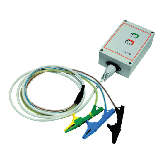
Page 11: Design
Design The LCI TX(-440) identifying generator is built into a sturdy ABS plastic housing. The unit is in protection class IP 54. The following figure shows the generators and their indicators and sockets: Item Description Power status LED LED for pulse, polarity and error indication... -
Page 12: Safety Mechanisms
The generator has a built-in overvoltage protection. If a voltage > 270 V protection (LCI TX) or >460 V (LCI TX-440) is detected, the fuses blow and, thus, protect the unit from being destroyed. After the overvoltage protection has been responded, it is necessary to change both internal 5A F fuses (high breaking capacity) in order to put the generator back to operating state. -
Page 13: Electrical Connection To Cable Under Voltage
Electrical Connection to Cable Under Voltage Introduction The generator has to be connected to the open distal (load) end of the cable. Proper cable identification using the CI RX can only be performed between the transformer and the generator. Connection sequence Greatest care must be taken when connecting the generator to ensure that the protective and neutral conductor are connected securely first. -
Page 14: 6.1 Connecting To Power Outlet
6.2 Connecting to low voltage distribution lines Measuring leads The LCI TX / LCI TX-440 is connected to open distributors by means of the measuring leads (black, blue and yellow/green). It is essential that the measuring leads are connected to the generator in accordance with the... - Page 15 Connection The LCI TX-440 generator can also be connected between two phases of between phases a multi-conductor cable. With this type of connection, the identification of (LCI TX-440) the cable is performed according to the “Twisted-Field” method by means of the optional TFS CI sensor (moved along or around the cable).
-
Page 16: Direct Connection To Lv Hrc Fuses (Optional)
6.3 Direct Connection to LV HRC fuses (Optional) Using the measuring cable MK 55 (available as a special accessory) the both generators, the LCI TX and the LCI TX-440, can be directly connected to LV HRC fuses of size 00 – 3 (6 … 630 A). - Page 17 Step Description Insert the plug-in adapter in the LV HRC fuse replacement handle. Push the plug-in adapter onto the upper contact blade so that it attaches securely to the fuse attachment. Detach the LV HRC fuse replacement handle. After the cable identification, disconnect by reversing this sequence of steps.
-
Page 18: Operating
Operating Polarity check The identifying generator switches itself on automatically after being connected to the cable. Subsequently, the generator automatically checks the polarity. This is necessary as the CEE 7/7 (Schuko) plug of the mains supply lead MK 37 may have been connected the wrong way round. Depending on the polarity, the system responds as follows: Correct polarity Wrong polarity... - Page 20 CI RX Cable Identifying Receiver USER GUIDE Issue: B (10/2021)
- Page 22 E: team.dach@megger.com Megger All rights reserved. No part of this handbook may be copied by photographic or other means unless Megger have before-hand declared their consent in writing. The content of this handbook is subject to change without notice.
- Page 23 Each component and product replaced in accordance with this warranty becomes the property of Megger. All warranty claims versus Megger are hereby limited to a period of 12 months from the date of delivery. Each component supplied by Megger within the context of warranty will also be covered by this warranty for the remaining period of time but for 90 days at least.
- Page 24 Table of Contents Safety Advice ........................6 Technical Description ......................7 Scope of Delivery ........................ 8 Design ..........................9 Start-up ..........................10 Operation ........................... 13 General Handling of the Device ....................13 Identifying a Cable Using the DC Pulse Method (Current Flow Direction Determination) ..14 Phase identification using the PAS CI (optional) ..............
-
Page 25: Safety Advice
It is not allowed and the warranty is voided if any accessories other than the original ones are used with the equipment. Products of Megger are continuously being enhanced according to the state of the technology but such enhancements shall not constitute any... -
Page 26: Technical Description
The receiver has to be operated in combination with one of the generators (LCI TX, LCI TX-440 or CI TX) which transmit specific pulses into the cable to be identified. -
Page 27: Scope Of Delivery
• 2 x 1.5 V AA batteries • Necessary Flexible identification clamp AZF 150-CI or AZF 250-CI • accessories Optional The following accessories can be ordered by your Megger representative, if accessories required: Order Accessories Description number Case Suitable for a complete cable... -
Page 28: Design
Design The CI RX identifying receiver is built into a sturdy ABS plastic housing. The integrated flexible identification clamp has a diameter of min. 240 mm (min. 130 mm optional) and a cable length of 1.5 m. The unit is in protection class IP 54. -
Page 29: Start-Up
To identify live cables in combination with the LCI TX or LCI TX-440 generator, the identification clamp should be placed around the cable with... - Page 30 In order to minimize the risk of stray field induction, the flexible identification clamp (including the connection cable) must be connected at a distance of at least 10 cm from nearby cables. If there is not enough room for this, then at least the clamp closure and the connection cable should be positioned as far away as possible from the nearby cables (see diagram).
- Page 31 Switching-on The unit can be switched-on by pressing the on/off button [ 5 ]. If the receiver is ready for operation, the power LED on the on/off button lights up green. Subsequent to the switch-on process, the green [ 1 ] and red [ 2 ] signal LEDs indicate for three seconds the preselected gain stage (1 up to 10).
-
Page 32: Operation
Operation General Handling of the Device Prior to the actual cable identification, a control measurement should be performed at the cable to be identified in the immediate vicinity to the generator in order to determine an adequate gain stage. The gain which can be adjusted in ten 3 dB-stages (-3 dB … 24 dB) using the soft keys [ 3 ] and [ 4 ] should be set to the lowest stage which causes all 10 signal LEDs to light up. -
Page 33: Identifying A Cable Using The Dc Pulse Method (Current Flow Direction Determination)
Identifying a Cable Using the DC Pulse Method (Current Flow Direction Determination) The signal level of the pulses transmitted by the generator is picked up by the flexible identification clamp and indicated by the green [ 1 ] or red [ 2 ] signal LEDs (depending on the direction of the current flow). -
Page 34: Phase Identification Using The Pas Ci (Optional)
Phase identification using the PAS CI (optional) When using the PAS CI to identify a single phase of an energized or de- energized cable (in combination with the LCI TX or the CI TX), the sensor must be placed as shown in the picture below. -
Page 35: Using The "Twisted-Field" Sensor ("Twisted-Field" Method And Load Current Detection)
The TFS CI sensor must be connected to the receiver instead of the identification tongs. Sensor orientation is not important in simple cable identification. LCI TX-440 or CI TX Process Due to the twist of the conductors along the cable, the fields formed around the two conductors are counter rotating.As the TFS CI sensor is moved... - Page 36 When examining the sensor travel along a twisted bifilar cable, the following signal behavior becomes apparent: Axial The gauge reacts to Longitudinal motion motion the connected cable Current flow: → An interval of min. 2 seconds is required between the individual motion phases, which corresponds to the signal pause of the identification generator.
- Page 37 (see images). The following diagram illustrates the signal response when the sensor is moved around a four-core cable in a radial direction: LCI TX-440 or CI TX The following diagram illustrates the signal response when the sensor is...
-
Page 38: Load Current Detection
6.4.2 Load Current Detection It is only possible to detect load current for shielded cables to a very limited degree. CAUTION Purpose The determination of the current flow direction and the “Twisted-Field” identification represent straightforward and reliable cable identification methods. An additional recording of load currents with a frequency of 50 Hz or 60 Hz can further increase the reliability of the cable identification in certain cases, e.g. - Page 39 Gain adjustment Setting the gain is performed in a similar way to the identification mode (see section 6.1). Unlike the identification mode, in load current detection mode, LEDs 1 and 10 flash to display overload. If this happens even when gain stage 1 is selected, then you should increase the distance between the sensor and the cable (e.g.
- Page 40 If a detectable current is flowing through the cable, then this is signaled by the red and green LEDs flashing every second. The following differentiation is made: Half-scale deflection Full-scale deflection Depending on the gain setting of the CI RX, the following conclusions can be drawn: Gain 1 …...
-
Page 41: Troubleshooting
• The cable to be identified consists of several parallel cables, resulting in current distribution of the test pulse (only for LCI TX / LCI TX-440). • The current in the cable to be identified is > 120 A or the transient disturbances are too high (only for LCI TX / LCI TX-440). - Page 42 Tento symbol indikuje, že výrobek nesoucí takovéto označení nelze likvidovat společně s běžným domovním odpadem. Jelikož se jedná o produkt obchodovaný mezi podnikatelskými subjekty (B2B), nelze jej likvidovat ani ve veřejných sběrných dvorech. Pokud se potřebujete tohoto výrobku zbavit, obraťte se na organizaci specializující se na likvidaci starých elektrických spotřebičů...
Need help?
Do you have a question about the LCI TX and is the answer not in the manual?
Questions and answers