
Related Manuals for Nortek 2GIG GC2


Summary of Contents for Nortek 2GIG GC2
- Page 1 GC2 Panel Installation and Programming Guide V1.16 Firmware WIRELESS SECURITY SYSTEM WARNING: OWNER’S INSTRUCTION NOTICE. Not to be removed by anyone except occupant.
-
Page 3: Table Of Contents
Programming Outline . . . . . . . . . . . . . . . . . . . . . . . . . . . . . . . . . . . . . . . . . . . . . . . . . . . . . . . . . . . . . . . . . . . . . . . . . . . . . 31 ANSI/SIA CP‐01 Compliance. . . . . . . . . . . . . . . . . . . . . . . . . . . . . . . . . . . . . . . . . . . . . . . . . . . . . . . . . . . . . . . . . . . . . . . . . . . . . . . . . . . . . 31 Programming Question Table. . . . . . . . . . . . . . . . . . . . . . . . . . . . . . . . . . . . . . . . . . . . . . . . . . . . . . . . . . . . . . . . . . . . . . . 32 Zone Numbering . . . . . . . . . . . . . . . . . . . . . . . . . . . . . . . . . . . . . . . . . . . . . . . . . . . . . . . . . . . . . . . . . . . . . . . . . . . . . . . . . 35 Sensor Types (Zones) . . . . . . . . . . . . . . . . . . . . . . . . . . . . . . . . . . . . . . . . . . . . . . . . . . . . . . . . . . . . . . . . . . . . . . . . . . . . . 36 Voice Descriptors . . . . . . . . . . . . . . . . . . . . . . . . . . . . . . . . . . . . . . . . . . . . . . . . . . . . . . . . . . . . . . . . . . . . . . . . . . . . . . . . 38 Equipment Codes . . . . . . . . . . . . . . . . . . . . . . . . . . . . . . . . . . . . . . . . . . . . . . . . . . . . . . . . . . . . . . . . . . . . . . . . . . . . . . . . 40 Installer Programming . . . . . . . . . . . . . . . . . . . . . . . . . . . . . . . . . . . . . . . . . . . . . . . . . . . . . . . . . . . . . . . . . . . . . . . . . . . . 41 Account Registration . . . . . . . . . . . . . . . . . . . . . . . . . . . . . . . . . . . . . . . . . . . . . . . . . . . . . . . . . . . . . . . . . . . . . . . . . . . . . . . . . . . . . . . . . . 41 Wireless (RF) Sensor Programming . . . . . . . . . . . . . . . . . . . . . . . . . . . . . . . . . . . . . . . . . . . . . . . . . . . . . . . . . . . . . . . . . . . . . . . . . . . . . . . 41 Q1: RF Sensor Programming Outline. . . . . . . . . . . . . . . . . . . . . . . . . . . . . . . . . . . . . . . . . . . . . . . . . . . . . . . . . . . . . . . . . . . . . . . . . . . . 42 Summary of RF Sensor # Screen . . . . . . . . . . . . . . . . . . . . . . . . . . . . . . . . . . . . . . . . . . . . . . . . . . . . . . . . . . . . . . . . . . . . . . . . . . . . . . . 42 RF Sensor Programming Questions . . . . . . . . . . . . . . . . . . . . . . . . . . . . . . . . . . . . . . . . . . . . . . . . . . . . . . . . . . . . . . . . . . . . . . . . . . . . . 42 Copyright © 2016 Nortek Security & Control... - Page 4 Q55: Opening Reports to CS (0‐1) . . . . . . . . . . . . . . . . . . . . . . . . . . . . . . . . . . . . . . . . . . . . . . . . . . . . . . . . . . . . . . . . . . . . . . . . . . . . . . . 59 Q56: Closing Reports to CS (0‐1) . . . . . . . . . . . . . . . . . . . . . . . . . . . . . . . . . . . . . . . . . . . . . . . . . . . . . . . . . . . . . . . . . . . . . . . . . . . . . . . . 59 Q57: Alarm Restore Reports to CS (0‐1) . . . . . . . . . . . . . . . . . . . . . . . . . . . . . . . . . . . . . . . . . . . . . . . . . . . . . . . . . . . . . . . . . . . . . . . . . . 59 Q58: Trouble Restore Reports to CS (0‐1). . . . . . . . . . . . . . . . . . . . . . . . . . . . . . . . . . . . . . . . . . . . . . . . . . . . . . . . . . . . . . . . . . . . . . . . . 59 Q59: Bypass Restore Reports to CS (0‐1) . . . . . . . . . . . . . . . . . . . . . . . . . . . . . . . . . . . . . . . . . . . . . . . . . . . . . . . . . . . . . . . . . . . . . . . . . 59 Q60: AC Restore Reports to CS (0‐1) . . . . . . . . . . . . . . . . . . . . . . . . . . . . . . . . . . . . . . . . . . . . . . . . . . . . . . . . . . . . . . . . . . . . . . . . . . . . . 59 Q61: System Low Battery Restore Reports to CS (0‐1) . . . . . . . . . . . . . . . . . . . . . . . . . . . . . . . . . . . . . . . . . . . . . . . . . . . . . . . . . . . . . . 59 Q62: RF Low Battery Restore Reports to CS (0‐1) . . . . . . . . . . . . . . . . . . . . . . . . . . . . . . . . . . . . . . . . . . . . . . . . . . . . . . . . . . . . . . . . . . 59 Q63: Phone Fail Detect (0‐1) . . . . . . . . . . . . . . . . . . . . . . . . . . . . . . . . . . . . . . . . . . . . . . . . . . . . . . . . . . . . . . . . . . . . . . . . . . . . . . . . . . . 59 Q64: Smart Test Reports . . . . . . . . . . . . . . . . . . . . . . . . . . . . . . . . . . . . . . . . . . . . . . . . . . . . . . . . . . . . . . . . . . . . . . . . . . . . . . . . . . . . . . 60 Q65: RF Jam Causes Trouble (0‐1) . . . . . . . . . . . . . . . . . . . . . . . . . . . . . . . . . . . . . . . . . . . . . . . . . . . . . . . . . . . . . . . . . . . . . . . . . . . . . . . 60 Q66: Daylight Saving (0‐1) . . . . . . . . . . . . . . . . . . . . . . . . . . . . . . . . . . . . . . . . . . . . . . . . . . . . . . . . . . . . . . . . . . . . . . . . . . . . . . . . . . . . . 60 Q67: Daylight Saving Start Month (01‐12) . . . . . . . . . . . . . . . . . . . . . . . . . . . . . . . . . . . . . . . . . . . . . . . . . . . . . . . . . . . . . . . . . . . . . . . . 60 Copyright © 2016 Nortek Security & Control...
- Page 5 Walk Test . . . . . . . . . . . . . . . . . . . . . . . . . . . . . . . . . . . . . . . . . . . . . . . . . . . . . . . . . . . . . . . . . . . . . . . . . . . . . . . . . . . . . . . . . . . . . . . . . . . . 67 Radio Status Test . . . . . . . . . . . . . . . . . . . . . . . . . . . . . . . . . . . . . . . . . . . . . . . . . . . . . . . . . . . . . . . . . . . . . . . . . . . . . . . . . . . . . . . . . . . . . . 68 Cell Phone Test . . . . . . . . . . . . . . . . . . . . . . . . . . . . . . . . . . . . . . . . . . . . . . . . . . . . . . . . . . . . . . . . . . . . . . . . . . . . . . . . . . . . . . . . . . . . . 68 Telephone Test . . . . . . . . . . . . . . . . . . . . . . . . . . . . . . . . . . . . . . . . . . . . . . . . . . . . . . . . . . . . . . . . . . . . . . . . . . . . . . . . . . . . . . . . . . . . . . . 69 Restore Default System Configuration . . . . . . . . . . . . . . . . . . . . . . . . . . . . . . . . . . . . . . . . . . . . . . . . . . . . . . . . . . . . . . . . . . . . . . . . . . . . 69 Soft Reset. . . . . . . . . . . . . . . . . . . . . . . . . . . . . . . . . . . . . . . . . . . . . . . . . . . . . . . . . . . . . . . . . . . . . . . . . . . . . . . . . . . . . . . . . . . . . . . . . . 69 Hard Reset . . . . . . . . . . . . . . . . . . . . . . . . . . . . . . . . . . . . . . . . . . . . . . . . . . . . . . . . . . . . . . . . . . . . . . . . . . . . . . . . . . . . . . . . . . . . . . . . . 69 Regulatory Information . . . . . . . . . . . . . . . . . . . . . . . . . . . . . . . . . . . . . . . . . . . . . . . . . . . . . . . . . . . . . . . . . . . . . . . . . . . 70 Wireless Product Notice. . . . . . . . . . . . . . . . . . . . . . . . . . . . . . . . . . . . . . . . . . . . . . . . . . . . . . . . . . . . . . . . . . . . . . . . . . . . . . . . . . . . . . . . 70 FCC Notice . . . . . . . . . . . . . . . . . . . . . . . . . . . . . . . . . . . . . . . . . . . . . . . . . . . . . . . . . . . . . . . . . . . . . . . . . . . . . . . . . . . . . . . . . . . . . . . . . . . 70 FCC Telephone Rules and Regulations. . . . . . . . . . . . . . . . . . . . . . . . . . . . . . . . . . . . . . . . . . . . . . . . . . . . . . . . . . . . . . . . . . . . . . . . . . . 70 Commercial Regulatory Listings. . . . . . . . . . . . . . . . . . . . . . . . . . . . . . . . . . . . . . . . . . . . . . . . . . . . . . . . . . . . . . . . . . . . . . . . . . . . . . . . 71 Limited Warranty . . . . . . . . . . . . . . . . . . . . . . . . . . . . . . . . . . . . . . . . . . . . . . . . . . . . . . . . . . . . . . . . . . . . . . . . . . . . . . . . 72 Copyright © 2016 Nortek Security & Control...
- Page 6 GC2 Wireless Security System | Installation and Programming Guide Copyright © 2016 Nortek Security & Control...
-
Page 7: Introduction
Important Information The 2GIG Go!Control security system conforms to the Security Industry Alarm Coalition’s ANSI/SIA CP‐01: Control Panel Standard‐Features for False Alarm Reduction. It also meets the residential security system certification criteria for the ETL Listed Mark. The recommended storage temperature for all Control Panels is ‐10°C to 60°C (14°F to 140°F). For optimal Control Panel use, operation temperature is 0°C to 49°C (32°F to 120°F). No altitude range limitations have been reported while transporting Control Panel. Installing the System in Residential Settings When installing the system in a residential setting, be aware of the following: • Fire warning systems must be installed in accordance with national codes. In the United States, fire warning systems must be installed in accordance with ANSI/NFPA 72 National Fire Alarm and Signaling Code and ANSI/NFPA 70 National Electric Code. • A permit may be required for this alarm system. Some cities and municipalities may require an alarm system permit. Before installing this system, always ensure that you are in compliance with any national, regional, and local laws, rules, and/or guidelines. • This system is intended for use with approved‐model smoke alarms only. For use as a smoke alarm system, there must be at least one (1) smoke alarm programmed into the Control Panel and must use only approved model smoke alarms. Visit the 2GIG Dealer Web Site at dealer.2gig.com. • Failure to follow ETL requirements voids this system’s ETL Listed mark. Failure to install the Control Panel and accessories in accordance with the ETL requirements documented in this manual voids its ETL Listed Mark. Copyright © 2016 Nortek Security & Control... -
Page 8: Installing The System In Commercial Settings
• Full Voice Response. The panel gives clear notifications that indicate system status, zone descriptions, alarms, and emergencies. • Date, Time, and Weather Display.* Scroll through the date, time, and daily weather forecast. Provides the ability to receive messages, including severe weather warnings. • Quick Access. The one touch access buttons allow the quickest help possible in an emergency. The front panel and buttons serve as controls as well as indicators. Pressing the button displays emergency icons on the display for Panic, Fire, and Emergency alarm activation (each has programmable options and can be enabled or disabled). Pressing the button changes the system display to the Home screen • Full Color Touch Screen. Control all system functions with an easy‐to‐use color touch screen puts a wide range of security and home automation controls at your fingertips. • Multiple Arming Options. Secure your home by arming your system “AWAY” or “STAY.” The Quick Arm/Exit and Bypass features offer added convenience. • Home Automation Radio Module. The built in Z‐Wave radio enables various home automation functions including HVAC, appliances, lighting, and lock control. • Two (2)‐way Response Over Cellular.* Two‐way voice lets central station operators listen in and talk to you when a signal is received, ensuring that the proper emergency response personnel will be dispatched if necessary. • Fully Self‐Contained. The fully self‐contained panel contains a backup battery, and allows 60 user codes and monitors up to 60 wireless zones including eight (8) key fobs and four (4) keypads. It also provides two (2) hardwired loops, 15 sensor types, a supervised bell output, and a programmable solid‐state control output. • Over‐The‐Air (OTA) Updates.* There’s no need to worry about the panel’s software becoming outdated. With the OTA function, the panel can be remotely updated with the latest software. • Remote Control Options.* Always be in control by remotely managing your system from a computer or web‐ enabled mobile phone (iPhone, Android, etc,). * Feature requires the optional GSM (Cellular) Radio module and an active account with an Remote Service Provider. Copyright © 2016 Nortek Security & Control... -
Page 9: Optional Accessories
• 2GIG GSM (Cellular) Radio Module. An on‐board digital communicators reports alarms and trouble to a Central Station receiver via the standard telephone network and a two (2)‐way voice communication with the Central Station. It also supports OTA updates and remote control of the system using telephone or a Web‐enabled device through the Internet. • 2GIG 900 MHz Transceiver Module. it sends and receives signals with wireless touch screen keypads and image sensors. Touch screen keypads allow remote control of the system through the same graphic interface design as the 2GIG Control Panel. Note that the 2GIG 900 MHz Transceiver Module, touch screen keypad, and image sensor are only available in some regions. • 2GIG Wireless Touch Screen Keypad. A wall‐mounted, full‐color, touch screen interface that provides many of the same easy‐to‐use keypad functions available on the Control Panel. It is designed for indoor use only and gives users the ability to control lights, thermostats, and door locks, as well as to view the status of every sensor zone. When the 2GIG 900 MHz Transceiver Module is installed in the Control Panel, the system can be programmed to communicate with up to four (4) Wireless Touch Screen Keypads. • 2GIG Go!Control POTS Module. The POTS (Plain Old Telephone Service) module offers the same features and the cellular module only over a land‐line (instead of cellular), such as two (2)‐way‐voice communication with the remote monitoring service. • 2GIG Go!Bridge IP Communicator. The Go!Bridge provides Internet connectivity between the monitoring service’s Central Station and the Go!Control® Panel (requires the 2GIG 900 MHz Transceiver Module and supports automatic firmware updates, provides interactive security services, and increases supervision using signal‐forwarding to the Central Station. • 2GIG Super Switch Takeover Module. The takeover module communicates with the 2GIG Control Panel and is designed to convert up to eight (8) pre‐wired zones to supervised wireless zones. • 2GIG Hardwire Conversion Kit. This kit provides installers with an easy way to convert the zones of a pre‐wired security alarm system to 2GIG wireless zones. The kit includes one (1) Super Switch Takeover Module (Wireless Takeover of an Alarm System, US Patent No. 8,638,218). You can also install two (2) additional modules, which provides installers with the capability to convert up to 24 pre‐wired security zones to wireless zones. Copyright © 2016 Nortek Security & Control... -
Page 10: System Configuration
System Configuration This illustration details the entire system configuration (including optional features). See "Optional Accessories" on page 7. Figure 1 Complete System Configuration Copyright © 2016 Nortek Security & Control... -
Page 11: Control Panel Features
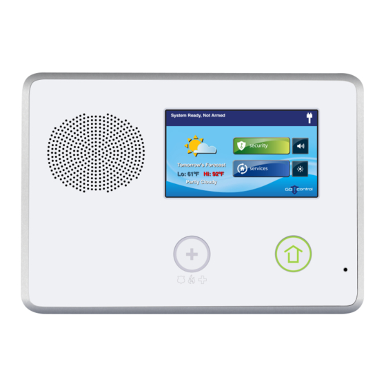
Figure 2 Control Panel External Features A Alarm Sounder and Speaker Sounds all system local alarms, voice prompts, system sounds, and audio for two (2)‐ way voice communications with the Central Station B Color Display with Touchscreen Shows all system information, status, programming, and functions as the keypad. Display cycles clock, calendar, and weather with an Alarm.com account (tap manually to change) C Microphone For voice communication with the Central Station D Emergency Button/Indicator Lights WHITE when enabled for emergency alarms and flashes during emergency alarms E Home Button/Indicator Sensor Status Lights GREEN when all sensors are closed (ready to arm) Not lit when any sensor is open (not ready to arm) Arming Status Lights RED when system is armed Flashes RED during the Entry Delay Alarm Memory Flashes RED during an alarm Flashes RED after an alarm while system is still armed Power Outage Flashes WHITE during power outage (system on battery backup) Flashes GREEN when all sensors are closed (ready to arm) Flashes ORANGE when any sensor is open (not ready to arm) Flashes RED while system is armed Copyright © 2016 Nortek Security & Control... -
Page 12: Internal Features
Figure 3 Control Panel Internal Features A Backup Battery Pack The standard backup battery that is included with all 2GIG Control Panels does not support UL 985 installations. To comply with the secondary supply requirement in UL 985 Household Fire Warning System Units, you must install the 2GIG Console Battery Pack (2GIG‐BATT2X). B Telephone Jack Used for RJ45 connection to installation's RJ31X telephone jack. See "Optional 2GIG Go!Control POTS Module" on page 16. C Terminal Block Connections for power, solid state output bell, and hardwire loops. D Alternate Power Supply Alternate connection for power. (Plug‐in barrel connector) E J4 Pin Connector Connector for the Firmware Update Cable used to update the firmware version on the Control Panel. F Optional Receiver Module 2GIG Go!Control POTS Module for over‐the‐air communication with the Central Station. See "Optional 2GIG Go!Control POTS Module" on page 16. G Main Receiver Module Receiver for peripheral device transmissions (or an optional 2GIG 900 MHz Transceiver Module for use with the Wireless Touch Screen Keypad). H POTS Module (Optional) 2GIG Go!Control POTS Module for connecting the lineman's phone (a.k.a., buttset) for monitoring the telephone line. See "Optional 2GIG Go!Control POTS Module" on page 16. I Third‐Hand Hanger Strap Hooks onto mounting plate during installation to hold the Control Panel while wiring. Copyright © 2016 Nortek Security & Control... -
Page 13: Installation Outline
Installation Outline Use the following outline in conjunction with this Installation and Programming Guide to guide you through the installation steps. Unpack the system and identify the system components. Create an Installation Floor Plan to determine the best centralized location for the Control Panel. Decide where to best install the wired and/or wireless sensors. Guidelines are available in the Installation Instructions included with each sensor. Identify an unswitched wall outlet to use for the Control Panel’s power supply. (Optional) Install the GSM (Cellular) Radio Module in the Control Panel. See "GSM (Cellular) Radio Module" on page 17. NOTE: (Optional) If installing the 2GIG Go!Control POTS Module, identify or install a USOC. RJ31X telephone jack to connect the module to the phone line. See "Optional 2GIG Go!Control POTS Module" on page 16. Use the Control Panel’s backplate to mark the drywall cutouts for the Control Panel. Then make the cutouts and attach the backplate to the wall. See "Control Panel Mounting Plate" on page 14. Install each of the system’s wireless sensors. If either of the two hardwire loops are going to be used, install the contacts and route the loop wire to the Control Panel’s wall cutout. Install the optional hardwired sounder, and route the connection wire to the Control Panel’s wall cutout. If used, route the telephone line from the RJ31X jack to the Control Panel’s wall cutout. Use the third‐hand hanger strap to hang the Control Panel on the mounting plate. Then connect all wiring to the Control Panel’s terminal block. See "Control Panel Wiring" on page 19 and "Terminal Block Wiring Diagram" on page 20. If you install the 2GIG Go!Control POTS Module, plug the telephone line into the POTS module. See "Optional 2GIG Go!Control POTS Module" on page 16. Plug the backup battery connector into the connector on the circuit board. Swing the Control Panel up, placing the bottom over the lip of the mounting bracket. Push the top of the Control Panel into the mounting bracket until it snaps into place, then secure it with the retaining screw. Plug the power supply into the unswitched wall outlet. Program the system as described in this manual and document any custom setup options for the end user in the space provided in the User Guide. Test the system as described "Installer Testing" on page 67. Educate the end user(s) about basic system operations and provide them with the Control Panel’s User Guide. Copyright © 2016 Nortek Security & Control... -
Page 14: Wireless Installation Tips
Wireless Installation Tips When installing any wireless system, consider certain limitations. Low power wireless transmitter signals do NOT broadcast equally through all types of construction materials. However, the Control Panel does contain a sensitive receiver that typically allows for placement of transmitters in nearly all locations. To determine the best possible placement for wireless sensors, review the following illustration. Figure 4 Wireless Installation Tips Copyright © 2016 Nortek Security & Control... -
Page 15: Sensors And Accessories
Four (4)‐Button Keyfob Remote • Panic Button Remote • Glass Break Detector • Wireless Smoke/Heat Alarm • Wireless Touch Screen Keypad • Wireless Keypad • Super Switch Takeover Module (Wireless Takeover of an Alarm System, US Patent No. 8,638,218) System Accessories • GSM (Cellular) Radio Module • Internal Antenna • External In‐Wall Antenna • External Attic Mount Antenna • Standard Battery Pack (UL 1023) • Console Battery Pack (UL 985) • Replacement Power Supply • Go!Bridge™ IP Communicator • Hardwire Conversion Kit Copyright © 2016 Nortek Security & Control... -
Page 16: Installation
• Ladder Remove the locking screw from the top of the Control Panel case and remove the mounting plate. Use the mounting plate as a template to mark the wall for the wiring cutout slot. Use a drywall saw to cut the slot. If using the optional GSM (Cellular) Radio Module with an external antenna, remove the plastic knockout labeled “EXTERNAL ANTENNA” on the mounting plate. Mark and cut a slot in the drywall for the external antenna. Attach the mounting plate to the wall using three (3) screws. Figure 5 Control Panel Mounting Plate A Mounting plate B Remove case screw and mounting plate C If using external antenna, remove knockout plate. D Use mounting plate as a template to mark wire cutout hole in dry wall. E Mount plate with three (3) screws. Wireless Sensors Install wireless sensors in the appropriate location using the Installation Instructions included with each wireless sensor as a guide. Hardwired Loops Hardwired loops can be programmed either Normally Open (N/O) or Normally Closed (N/C). End‐of‐Line Resistors (EOLR) can also be used to supervise the loops. Only contacts should be used with the hardwired loops. NOTE: The Control Panel does not support powering external devices (PIR’s, etc.). NOTE: Hardwired loops cannot be used for a CO or Fire sensor loop. If either of the two (2) hardwired loops are going to be used, install the contacts and then route the loop wire to the Control Panel’s wall cutout. If end‐of‐line supervision is required for the loop, install a 2.2kΩ resistor (not supplied) as shown in Figure 6 Hardwired Loop Wiring. Copyright © 2016 Nortek Security & Control... -
Page 17: Wiring
Figure 6 Hardwired Loop Wiring Figure 7 Remote Alarm Sounder WARNING: To avoid damage to the output, do NOT WARNING: Stranded conductors clamped under wire‐ connect an electromechanical bell to these terminals. binding screws or similar parts shall have the individual The bell terminals can be supervised. If Q21: Siren strands soldered together or arranged in a construction Supervision Time is set to (1) Enabled, and the wire that has been determined to be the equivalent. between the Control Panel and sounder is cut, the Control Panel displays a trouble alert message for siren supervision and sends a bell trouble report to the Central Station. Install the remote sounder in a secure location where it will be easily heard by occupants. Route wiring from the remote sounder location to the Control Panel’s wall cutout. NOTE: If the piezo alarm siren for the remote sounder has an extremely low current draw or the sounder produces hum or noise, install an 820Ω resistor in parallel with the sounder. Copyright © 2016 Nortek Security & Control... -
Page 18: Solid State Output
The output can switch up to 250 mA @ 16 VDC to ground. telephone line can be connected. NOTE: For ETL Listing, an external DC Backup Power Supply Figure 9 2GIG Go!Control POTS Module is required for a load connected to Terminal 4. NOTE: When the Control Panel is connected with an AC power source, Terminal 1 provides DC Power only. Figure 8 Solid State Output When the digital communicator activates, all local telephones are disconnected to prevent an off‐hook telephone on the premises from blocking the digital communicator’s call. Figure 10 2GIG Go!Control POTS Module Installation This output only functions while the Control Panel is receiving power from the wall power supply. Install the device to be controlled by the solid state output. Route wiring from the device location to the Control Panel’s wall cutout. WARNING: To avoid damage to the output, do NOT connect an electromechanical bell to these terminals. Copyright © 2016 Nortek Security & Control... -
Page 19: Gsm (Cellular) Radio Module
Plug one end of the modular cable into the jack and slide it through the hole in the mounting plate into the wall. Power ON the Control Panel. Access the System Configuration screen as follows: At the Home screen, tap the system logo in the lower‐right corner. At the Enter Your Code screen, enter the master installer code (the default code is 1561). At the Installer Toolbox screen, tap System Configuration. Tap Go To and then enter the code shown below to respond to these programming questions: • Enter 08. For details, see"Q8: Dialer (0‐1)" on page 52. • Enter 11. For details, see "Q11: CS #1 Phone Number (0‐25 Digits)" on page 53. • Enter 12. For details, see "Q12: CS #1 Account Number (4 Digits)" on page 53. A GSM (Cellular) Radio Module Connector B End of antenna hangs down inside the wall NOTE: The routing of the antenna wire is critical. You must route the wire exactly as directed or cell radio interference will occur. When using external antennas, plug the antenna connector into the GSM (Cellular) Radio Module. The antenna drops into the wall or mounts in the attic with Copyright © 2016 Nortek Security & Control... - Page 20 Go!Control Wireless Security System | Installation and Programming Guide the cable passing through the slot in the Control Panel’s mounting plate. Figure 13 Attic Antenna Installation A Attic antenna mounted as high as possible B Coaxial cable to Control Panel The GSM (Cellular) Radio Module should already be activated by the factory. If not, contact the Remote Service Provider. For the GSM (Cellular) Radio Module to function, it must be activated before it can be enrolled. Enrollment is accomplished by creating an account with the provider. Copyright © 2016 Nortek Security & Control...
-
Page 21: Control Panel Wiring
Installation Control Panel Wiring The following diagram shows you the Control Panel wiring. Figure 14 Control Panel Wiring Diagram Copyright © 2016 Nortek Security & Control... -
Page 22: Control Panel Wiring
Figure 16 Terminal Block Wiring Diagram Wire Size and Length To ensure proper operation, do NOT exceed the following maximum length for the wire size installed: Wire Size Maximum Length 22 AWG 55 ft (16.8 m) 20 AWG 85 ft (25.9 m) 22 AWG 2‐pairs 110 ft (33.5 m) (19 AWG equivalent) 18 AWG 135 ft (41.1 m) TIP: To ensure that the appropriate wire size and length is installed, measure the voltage between the power connection terminals at the back of the Control Panel. The voltage measured must not fall below 11 volts DC or the Control Panel may display nuisance “AC Power Loss” messages and send AC Loss Reports to the Central Station. See "Q52: AC Loss Reports to CS (0‐1)" on page 14 VDC Power Input (+) 14 VDC Power Input (‐) Ground Open Collector Bell (+) Bell (‐) Hardwire Loop 1 Hardwire Loop 2 Copyright © 2016 Nortek Security & Control... -
Page 23: Control Panel And Power Supply Mounting
Figure 19 Securing the Power Supply A Left Terminal 14 VDC (+) C 14 VDC (+) Terminal 1 B Right Terminal 14 VDC (‐) D 14 VDC (‐) Terminal 2 Control Panel and Power Supply Mounting After all the wiring complete, follow these steps to power 1 Place the screw here for a bracket on a standard style outlet. up the Control Panel: 2 Place the screw here for a bracket on a decora style outlet. Place the bottom of the Control Panel over the lower lip of the backplate and flip the Control Panel upwards. NOTE: In the United States (and other countries where it is Then push the Control Panel over the mounting bracket required), use the power supply retaining bracket. In until it snaps into place. it with the retaining screw. Canada, the power supply retaining bracket is not required. Copyright © 2016 Nortek Security & Control... -
Page 24: Commercial Installations
Commercial Installations For commercial installations, the Control Panel is designed for use only as a burglary alarm system, and not for fire protection. Installation location and wiring methods shall be in accordance with ANSI/NFPA 70: National Electric Code, UL 681: Installation and Classification of Burglar and Holdup Alarm Systems, and UL 827: Central‐Station Alarm Services. NOTE: When used with the Alarm.com service, this security system has been evaluated and complies with UL 1610: Central‐ Station Burglar Alarm Units. For commercial UL 1610 installations, you must install the GSM (Cellular) Radio Module. See "GSM (Cellular) Radio Module" on page 17. NOTE: All entries and exits within a commercial installation setup must be protected according to the criteria provided by UL 681: Installation and Classification of Burglar and Holdup Alarm Systems. Figure 20 Commercial Installations Copyright © 2016 Nortek Security & Control... -
Page 25: Nfpa Standard 72
NFPA Standard 72 In the United States and Canada, smoke detectors must be installed in accordance with National Fire Protection Association (NFPA) Standard 72: National Fire Alarm and Signaling Code, which reads as follows: “2‐1.1.1 Smoke alarms shall be installed outside of each separate sleeping area in the immediate vicinity of the bedrooms and on each additional story of the family living unit including basements and excluding crawl spaces and unfinished attics. In new construction, a smoke alarm shall be installed in each sleeping room. 2‐1.1.2 For family living units with one or more split levels (i.e., adjacent levels with less than one full story separation between levels), a smoke alarm shall suffice for an adjacent lower level, including basements. (Exception: Where there is an intervening door between one level and the adjacent lower level, a smoke alarm shall be installed on the lower level.) • Ceiling mounted smoke alarms should be located in the center of the room or hall, or not less than 4 inches from any wall. When the alarm is mounted on a wall, the top of the alarm should be 4 to 12 inches from the ceiling. • Do not install smoke alarms where normal ambient temperatures are above 100°F (37.8°C), or below 40°F (4°C). Also, do not locate alarm in front of air conditioners, heating registers, or other locations where normal air circulation will keep smoke from entering the detector. A‐2.5.2.1 Smoke Detection ‐ Are More Smoke Alarms Desirable? The required number of smoke alarms might not provide reliable early warning protection for those areas separated by a door from the areas protected by the required smoke alarms. For this reason, it is recommended that the residential user consider the use of additional smoke alarms for those areas for increased protection. The additional areas include the basement, bedrooms, dining room, furnace room, utility room, and hallways not protected by the required smoke alarms. The installation of smoke alarms in kitchens, attics (finished or unfinished), or garages is not normally recommended, as these locations occasionally experience conditions that can result in improper operation or false alarms.” NOTE: Smoke alarms are not to be used with detector guards unless the combination has been evaluated and found suitable for the purpose. Figure 21 Recommended Smoke Alarm Locations Copyright © 2016 Nortek Security & Control... -
Page 26: Main Display Screens
• Display OFF. Turn OFF the Control Panel screen. Figure 22 Home Screen Menu Screen The Menu screen includes the Arm and Toolbox buttons. Figure 25 The Menu Screen Security Screen The Security screen displays three (3) buttons for Arm, Menu, and Status. It also shows the time, date, and weather display (requires that the feature is supported by the Remote Service Provider). Figure 23 Security Screen If any of the 24‐hour emergency options are enabled, an Emergency button also appears. It also includes these options: • Chime Select this check box to enable system chimes and clear the check box to disable system chimes. Note that chimes can also be enabled or disabled for each sensor number by tapping Toolbox and then Chimes Setup. Under the appropriate conditions, additional buttons • Voice Select this check box to enable voice include: announcements for the system. Voice announcements always sound during alarm conditions. Copyright © 2016 Nortek Security & Control... -
Page 27: System Status Screen
Main Display Screens System Status Screen stops the announcement of the system status during the status display. The System Status screen lists system status and any alerts. The date and time of alerts are listed in the displayed log. Figure 26 System Status Screen One option button for Silence is displayed; it temporarily Copyright © 2016 Nortek Security & Control... -
Page 28: Toolbox And Installer Toolbox
Accessing the Installer Toolbox Each screen provides different buttons for accessing There are two (2) ways to access the Installer Toolbox on different features. the Control Panel: Figure 28 Toolbox (1 of 3) • At the Home screen, tap the system logo in the lower‐ right corner and then tap the Installer Toolbox button. Finally, enter the installer code. • At the Home screen, tap Security > Menu > Toolbox. Then tap the Installer Toolbox button and enter the installer code. The default installer code is 1561. To learn how to change this code, see Q43: Installer Code (4 Digits). Accessing the System Configuration for System and Sensor Programming To access the system configuration screens for programming sensors into the system: Tap Disarm and enter a valid user code. The default user code is 1111. Access the Installer Toolbox. See Accessing the Installer Toolbox above. At the Installer Toolbox screen, tap the System Configuration button. Copyright © 2016 Nortek Security & Control... -
Page 29: System Configuration Screens
Panel settings and provide access to a variety of system Configuration for System and Sensor Programming. tests. The System Configuration screens present installers with a sequential list of programming questions. For a list of all Figure 31 Installer Toolbox Screen available programming questions, see "Programming Question Table" on page 32. Figure 32 Q1: Select RF Sensor # (01-48, 63-74). After tapping the System Configuration button, the first programming question appears. To learn more, see System Configuration Screens. TIP: To simplify programming, questions are arranged so System Configuration Screens that commonly used values appear early in the question Use the System Configuration screens to program sensors sequence. into the system. Installers can access the System Copyright © 2016 Nortek Security & Control... -
Page 30: System Status Icons
Figure 35 AC Power OFF Figure 41 Cell Radio The AC Power icon shows the status of the AC power to the Control Panel. A RED “X” appears If the option GSM (Cellular) Radio Module is over the WHITE plug when AC power is absent. installed, the Cell Radio icon appears while the Control Panel is receiving Over‐the‐Air (OTA) firmware updates. Phone Line Failure Interior sensor open Figure 36 Phone Line Failure Figure 42 Interior Sensor Open If the Control Panel detects that the telephone If an interior sensor is open (or a motion line is disconnected, the phone line failure icon detector has just been activated) this icon appears. appears. As a warning, the icon flashes during arming. Copyright © 2016 Nortek Security & Control... -
Page 31: Programming Navigation
Tap Back to highlight the previous word in a multi‐ options do not display a Skip button. word data field. The Back button displays the previous screen in some cases. Figure 44 Questions without Sub-options • Tap Shift to reveal alternate characters on the keypad that can be used for data entry. Figure 46 Questions with Data Entry • The ↑ and ↓ arrows select the next or previous programming question. • The ← and → arrows choose values for the ques on or move the cursor left and right along the white data entry field. Questions with Sub-Options Some of the programming questions have sub‐options. They navigate as follows. Questions with sub‐options display a Skip button during the question. The Skip button advances to the next programming question/section. Copyright © 2016 Nortek Security & Control... -
Page 32: Additional Buttons
Go!Control Wireless Security System | Installation and Programming Guide Additional Buttons • Tap Exit to exiting the programming module. Depending on the programming question, additional Figure 47 Other Buttons Displayed buttons may be displayed on screen: • Tap Esc (Escape) to “undo” the previous action. This is useful when you want to restore the previous value for the question or sub‐question. • Tap Sum (Summary) to reveal a summary of the values stored for the question and sub‐options. • Tap End to reveal a summary of the values stored for the entire Control Panel memory. • Tap Learn to set the system to receive a sensor’s serial number during programming. • Tap Paste to repeat the last sensor serial number entered. Copyright © 2016 Nortek Security & Control... -
Page 33: Programming Outline
Q27 Exit Delay Restart (1) Enabled (0) Disabled or (0 to 1) (1) Enabled Toolbox. Q31 Enter Cancel Time, in 5 Minutes 6‐254 Minutes When prompted, enter the master user code. The Minutes (5‐255) default master user code is 1111. Q32 Select Cancel (1) Enabled (0) Disabled or Tap the User Management button and then setup the Display (0 to 1) (1) Enabled user codes. Be sure to set up the Duress Code as User Q35 Select Abort Win‐ 30 Seconds 15 to 45 Seconds #8. Tap Back when finished. dow Dialer Delay (0 to 2) Q78 Select Output (11) Follows NOTE: See "Q78: Tap Brightness/Volume and set the levels for the Internal Sounder Output" on installation. Alarm page 61 Copyright © 2016 Nortek Security & Control... -
Page 34: Programming Question Table
0000000 Select RF Keypad # Emergency Age (01) (0) New Select RF Keypad # Emergency Keys (01) (1) Enabled Construct RF Keypad # Voice Descriptor Keypad # Enter Exit Delay, in Seconds (45 to 120) 60 seconds‡ Enter Entry Delay 1, in Seconds (30 to 240) 30 seconds‡ Enter Entry Delay 2, in Seconds (30 to 240) 45 seconds‡ Select Dialer (0 to 1) (0) disabled Enter Dialing Prefix (0 to 4 digits) No default Enter Call Waiting Disable Code (0 to 6 digits) No default‡ Enter CS #1 Phone Number (0 to 25 digits) No default Enter CS #1 Account Number (4 digits) No default Select Two‐Way Voice (0 to 2) (1) Stay Online Select Silent Panic/Burglary Listen Only (1 to 1) (1) Enabled Select Dialing Type (0 to 1) (0) Touch Tone Select Police Emergency Key (0 to 2) (1) Audible Select Fire Emergency Key (0 to 1) (1) Audible Select Emergency Key (0 to 1) (1) Audible Select Quick Arming (0 to 1) (1) Enabled Select Swinger Shutdown Count (1 to 6) (2) Two Trips‡ Copyright © 2016 Nortek Security & Control... - Page 35 (2) 2nd Select Daylight Saving End Month (01 to 12) (11) November Select Daylight Saving End Sunday (1 to 7) (1) 1st Select System Tamper Causes Trouble (0 to 1) (1) Enabled Select Quick Bypass (0 to 1) (0) Disabled Select Disarming Keyfob After Alarm Alert (0 to 1) (0) Disabled Select Keyfob Arm/Disarm Confirmation (0 to 1) (0) Disabled Select Auto Unbypass for Manual Bypass (0 to 1) (1) Enabled Select Force Bypass Reports (0 to 1) (0) Disabled Select Event Log (0 to 3) (3) All Events Select Output (00‐12) (11) Follows Internal Sounder Alarm‡ Select Z‐Wave Feature (0 to 3) (3) Enabled with Local Rules Select Z‐Wave Switches Feature (0 to 1) (1) Enabled Select Z‐Wave Thermostats Feature (0 to 1) (1) Enabled Select Z‐Wave Door Locks Feature (0 to 1) (1) Enabled Select Temperature Display Units (0 to 1) (0) Degrees Fahrenheit Select date and time format (0 to 2) (0) MM‐DD‐YY H:MM AM/PM Copyright © 2016 Nortek Security & Control...
- Page 36 (0) DHCP If (0) DHCP is selected in Select Configuration Source (0 to 1), (1) Port 1 the following sub‐questions appear: NOTE: This option is automatically selected if you choose (0) DHCP in the previous question. Typically, you will skip this Select Port # (1 to 8) question unless additional programming is required. Select Used (0 to 1) (0) Disabled NOTE: Typically, you will skip this question unless additional programming is required. Enter Port Value (0‐65535) NOTE: Only appears if (1) Enabled is selected in Select Used (0 to Enter Port Forward IP Address 000.000.000.000 NOTE: Only appears if (1) Enabled is selected in Select Used (0 to NOTE: Typically, you will accept the default IP address value that appears. If (1) Static is selected in Select Configuration Source (0 to 1), the following sub‐questions appear Enter Device IP Address Enter Gateway IP Address Enter Subnet Mask Enter Broadband Network Failure Time (1‐255) Select Broadband Network Failure Causes Trouble (0 to 1) (1) Enabled Select Broadband Network Failure Reports (0 to 1) (1) Enabled Select send report 3 times on panel tamper (0 to 1) (1) Enabled** Select sound on normal closing acknowledgment (0 ‐ to‐1) (1) Enabled** ‡ Indicates the default se ng for ANSI/SIA CP‐01 compliance * To comply with UL 985:Household Fire Warning System Units, the setting for Q46: Select Trouble Doesn’t Sound at Night must be set to (0) Disabled. ** To comply with UL 1610: Central‐Station Burglar‐Alarm Units, Q96and Q97 must beset to (1) enabled. UL 1610 compliance also requires that Q91: Select Radio Modem Supplier be set to (1) Radio Modem Supplier 1. Copyright © 2016 Nortek Security & Control...
-
Page 37: Zone Numbering
Zone Numbering The Control Panel supports 60 wireless protection zones. When programming zones, keep the following numbering ranges in mind: Zones Descriptions 1‐48 Wireless Zones 47‐48 Wireless Cross‐Sensor Zone 49‐50 Wired Zones 51‐58 Keyfobs 59‐62 Keypads 63‐74 Wireless Zones Duress Fire Medical Police Panic Copyright © 2016 Nortek Security & Control... -
Page 38: Sensor Types (Zones)
(08) 24‐Hour Auxiliary Alarm This sensor type is continuously armed 24‐hours a day. A sensor programmed to this type will trigger an alarm regardless of the mode the system is in. The bell output will not activate, but the local sounder will continue until it’s acknowledged at the Control Panel. Typical use would be for a monitoring device such as a flood or temperature sensor. There is no time out for the internal sounder, it will continue until a user code is entered. (09) 24‐Hour Fire † This sensor type is continuously armed 24‐hours a day. A sensor programmed to this type will trigger the local alarm fire sounder and the bell output regardless of the mode the system is in.Typical use would be for wireless smoke detectors. This sensor type is always active and cannot be bypassed. (10) Interior with Delay This sensor type operates as a delayed sensor when the system is armed in the Away mode, and when triggered, will start the Entry Delay 1 timer. If the system is armed in Away mode with no Entry Delay (armed instant), this sensor type will trigger an instant alarm. If the system is armed in Stay mode (or Stay mode with no Entry Delay), this sensor type will be bypassed. (14) 24‐Hour Carbon Monoxide This sensor type is continuously armed 24‐hours a day. A sensor programmed to this type will trigger the † local alarm pulse sounder and the bell output regardless of the mode the system is in. Typical use would be for wireless carbon monoxide detectors. This sensor type is always active and cannot be bypassed. (16) 24‐Hour Fire with This sensor type is continuously armed 24‐hours a day. A sensor programmed to this type can trigger the Verifica on † local alarm fire sounder and the bell output regardless of the mode the system is in. Typical use would be for wireless smoke detectors. This sensor type is always active and cannot be bypassed. For verification, this sensor type must be violated twice in two (2) minutes, or remain violated for 30 seconds. If any other fire sensor (verified sensor type or not) violates within two minutes, both sensors will cause a fire alarm. (23) No Response Type This sensor type is a special zone that can be monitored for activity or inactivity by the Central Station. It does not affect security system status. (24) Silent Burglary This sensor type is for silent triggering the burglary alarm with perimeter doors and windows that will not be used to enter or exit the protected premises while the system is armed. The Control Panel’s sounder and the bell output will not activate. An instant silent alarm will occur when this type of sensor is triggered with the system armed in either the Stay or Away mode. Copyright © 2016 Nortek Security & Control... - Page 39 Sensor Types (Zones) Sensor Type (Zone) Description (32) Remote Device* This zone type is selected by the installer when pairing the panel with peripheral devices that can utilize localized troubles (such as RF jam, low battery, tamper, or AC loss detected by the peripheral device). This sensor is continuously active and will cause a trouble at the panel for all problem conditions. When the panel is in an armed state, this sensor type will cause an alarm for TAMPER and RF JAM. All trouble conditions will be sent to the monitoring station if reporting is enabled with the exception of AC LOSS. This will only de displayed at the panel. † Indicates Sensor types that are not allowed for hardwired loops. * Sensor Type Reporting is only supported on Alarm.com. Copyright © 2016 Nortek Security & Control...
-
Page 40: Voice Descriptors
CABINET ENTRANCE HANGING CANCEL ENTRY HANGUP NINE CARBON MONOXIDE 071 ERROR HEAT NINETEEN CELLAR EXERCISE HIGH NINETY CELLULAR EXIT HOME NORTH CELL RADIO EXIT NOW HOUSE CENTER EXTERIOR NOT READY CHECK EXTERNAL INSIDE NO DELAY CHEST FAILURE INSTANT NO ENTRY DELAY CHILDREN'S FAMILY INTERIOR NURSERY CHIME Copyright © 2016 Nortek Security & Control... - Page 41 REAR SUPERVISION YARD GIRL’S RELAY SYSTEM ZERO IMAGE REMOTE TAMPER ZONE IMAGE SENSOR REPEAT TEMPERATURE BALCONY RF JAM COURTYARD SON’S RIGHT TERMINATED DECK ROOM THERMOSTAT DETACHED THEATER SAFE THIRD OVERHEAD WING SECOND THIRTEEN REFRIGERATOR SWITCH Copyright © 2016 Nortek Security & Control...
-
Page 42: Equipment Codes
2GIG Glass Break Detector (0866) 2GIG 4‐Button Keyfob Remote (0867) 2GIG Wireless Keypad (0868) 2GIG Panic Button Remote (0869) 2GIG PIR with Pet Immunity (0871) SMKE1‐345C Smoke Detector (Canada) (0872) SMKE1‐345 Smoke Detector (USA) (0873) 2GIG Takeover Module (0895) SMTK2‐345 GE Smoke/Heat Detector (USA/Canada) (1026) 2GIG CO Detector (1058) 2GIG Smoke Detector (1059) 2GIG‐TS1 Wireless Touchscreen Keypad (1061) Tilt Sensor (1062) 2GIG Tilt Sensor (1063) 2GIG Doorbell (1064) 2GIG Bypass Sensor (1065) 2GIG Flood Sensor (1067) 2GIG Repeater (1068) 2GIG Translator (9999) Alarm.com Image Sensor Copyright © 2016 Nortek Security & Control... -
Page 43: Installer Programming
Dialer Abort screen. RF sensors # 01‐48 and #63‐74 report as wireless zones 01‐ • Q: Construct RF Sensor # Voice Descriptor. Specify 60. the name assigned to the sensor that is announced Programming questions for RF sensor programming if this feature is programmed. include: • Q: Select RF Sensor # Reports. Specify (0) Disabled • Q1: Select RF Sensor Number. Select sensor number or (1) Enabled whether or not RF sensors trigger a 01‐48 or 63‐74. report to the Central Station. • Q: Select RF Sensor # Type. Select (01) Exit/Entry 1, • Q: Select RF Sensor # Supervised. Specify whether (02) Exit/Entry 2, (03) Perimeter, and so on. For or not the Control Panel checks for status reports options, see "Zone Numbering" on page 35. from the sensor. • Q: Select RF Sensor # Equipment Type. Some • Q: RF Sensor # Chime. Select voice announcement sensor types ask for the equipment type, others do and chime options for the sensor. not. See "Q: Select RF Sensor # Equipment Type" on page 43. Copyright © 2016 Nortek Security & Control... -
Page 44: Q1: Rf Sensor Programming Outline
Q1: Select RF Sensor # (01-48, 63-74) Up to 60 wireless RF sensors can be used with each Control Panel. The options for each sensor are programmed with sub‐option questions. Enter the RF sensor number or tap the ← or → arrows to select it. Program the sensor details by using the ↑ and ↓ arrows to select each of the sub‐options. NOTE: To skip Q1 and jump directly to Q2 for Wired Sensor Programming, tap Skip. Q: Select RF Sensor # Type DEFAULT: (00) Unused Answer this question to define the sensor type (zone). Simply enter the appropriate code (see table below) or tap the ← or → arrows to select the desired zone. In the table below, a “Y” indicates the sensor type can be assigned. A “N” indicates the sensor type is not used, and an asterisk (*) denotes that selecting this sensor type also requires you to answer the Q: Select RF Sensor # Equipment Scroll between op ons using the ← and → arrows. Move to Type question. the previous or next prompt by tapping the ↑ and ↓ Sensor Types (Zone) Wired arrows. (00) Unused To program another sensor tap Next. (01) Exit/Entry 1 Copyright © 2016 Nortek Security & Control... - Page 45 Q: Enter RF Sensor # Serial Number (7 Digits) sensor’s serial number. (The sensor number will be filled in automatically if Learn is used.) DEFAULT: 0000000 RF sensor serial numbers can be manually entered or Q: Select RF Sensor # Dialer Delay (0 to 1) automatically transmitted from the sensor to the Control DEFAULT: (1) Enabled Panel. If this feature is enabled, the delay time must be set to a • For manual entry. Enter the sensor number that minimum of 30 seconds for ANSI/SIA compliance. To set the was logged for the sensor being programmed. Tap Shift to access alphabetic characters. Copyright © 2016 Nortek Security & Control...
-
Page 46: Wired Sensor Programming
Q: Wired Sensor # Equipment Code. Select the • To turn off supervision for this RF sensor, select (0) four (4)‐digit equipment code that corresponds Disabled. to the appropriate sensor model. See NOTE: Portable sensors such as panic buttons should not "Equipment Codes" on page 40. be set as supervised if the sensor will be removed from • Q: Wired Sensor # Equipment Age. Specify the premises at times. whether the sensor is a (0) New or (1) Existing sensor. Q: Select RF Sensor# Chime (00 to 13) • Q: Wired Sensor # Normal State. Choose DEFAULT: (0) Disabled between (0) Not Used, (1) Closed, (2) Open, (3) Each RF sensor can be set to sound a “ding‐dong” chime End‐Of‐Line‐Resistor. and/or sound its voice descriptor when the sensor is • Q: Wired Sensor # Dialer Delay. Specify triggered. This step determines the initial setting for the whether to use delayed or instant digital sensor. communicator reports for the sensor. The delay time is set on the Dialer Abort screen. The end user can change the chime setting for sensors using Chime Setup in the User Toolbox. Copyright © 2016 Nortek Security & Control... -
Page 47: Q2: Wired Sensor Programming Outline
NOTE: To skip wired sensor programming, tap Skip to jump from question Q2 to question Q3. See "Wireless (RF) Key Fob Programming" on page 47. Q: Select Wired Sensor# Type DEFAULT: (00) Unused Each wired sensor needs to be assigned to a sensor type. Select the sensor type that matches the wired sensor’s func on using the ← or → arrows or enter the sensor type number directly on the keypad. In the table below, a “YES” indicates the sensor type can be used for the wired sensor. An “NO” indicates the sensor type is not used. Sensor Types (Zones) RF Wired Scroll between op ons using the ← and → arrows. Move to Sensors Sensors the previous or next prompt by tapping the ↑ and ↓ (00) Unused arrows. (01) Exit/Entry 1 To program another sensor tap Next. (02) Exit/Entry 2 (03) Perimeter Copyright © 2016 Nortek Security & Control... - Page 48 Q: Select Wired Sensor# Equipment Age (0 to 1) DEFAULT: (0) New • The default setting (1) Enabled activates reporting for this wired sensor number. The Control Panel can be used with new or existing wired sensors. • To prevent reporting for this wired sensor number, select (0) Disabled. • If this wired sensor is new for the installation, leave the default setting of (0) New. Q: Select Wired Sensor# Chime (00 to 13) • If this wired sensor is already installed, select (1) DEFAULT: (0) Disabled Existing. Each wired sensor can be set to sound a “ding‐dong” chime and/or sound its voice descriptor when the sensor is Q: Select Wired Sensor# Normal State triggered. DEFAULT: (0) Not Used Copyright © 2016 Nortek Security & Control...
-
Page 49: Wireless (Rf) Key Fob Programming
The Control Panel can be programmed with up to eight (8) • Q: Select Fob # Emergency Key. Choose the RF key fobs. function of double‐tapping the top buttons (0) Programming the fobs into the Control Panel involves Disabled, (1) Auxiliary Alarm, (2) Audible Alarm, (3) selecting the sensor number for a particular device, setting Silent Panic, or (4) Fire. or learning the serial number, and selecting the other • Q: Select Fob # Key # Can Disarm. Choose (0) options for the sensor. Disabled or (1) Enabled to specify if the key fob is allowed to disarm the system. IMPORTANT: RF key fobs 1 ‐ 8 report to the Control Panel as sensors 51 ‐ 58 (opening/closing, emergency, and low • Q: Construct Fob # Voice Descriptor. Construct the battery reports). name assigned for the keyfob announcement. See "Voice Descriptors" on page 38. Fob # Reports as Sensor # • Q: Select Fob # Arm No Delay. Choose if key fob will arm the system instantly without an exit delay. • Q: Select Fob # Key # Output. Select an action for the key fob auxiliary button. 4 Copyright © 2016 Nortek Security & Control... -
Page 50: Key Fob Programming Outline
• The default setting is (0000) Other. • Select (0866) 2GIG 4‐button Key Fob remote for a 2GIG‐KEY2 key fob remote. • Select (0577) Existing Key Fob for an existing key fob remote. NOTE: Only 2GIG 4‐Button Key Fob Remotes are compatible with this system. Q: Enter Key Fob # Other Equipment Code (0-9999) Scroll between op ons using the ← and → arrows. Move to DEFAULT: 0 the previous or next prompt by tapping the ↑ and ↓ arrows. NOTE: This question is only displayed if (0000) Other is selected for a key fob’s equipment code. To program another sensor tap Next. To exit programming, tap Skip, then End, and then Exit. • The equipment code is a four (4)‐digit code that is Upon exit, the panel takes several seconds to restart. assigned to the model of key fob being used. TIP: Tap Skip to jump to question Q4. See "RF Keypad • Enter the equipment code number for the key fob. Programming Questions" on page 50. Copyright © 2016 Nortek Security & Control... -
Page 51: Wireless (Rf) Keypad Programming
Disabled. code. • Select RF Keypad # Serial #. Enter the serial number Q: Construct Fob# Voice Descriptor from the keypad or “learn” by sending a signal. DEFAULT: (#) Keyfob • Select RF Keypad # Equipment Age. Select (0) New The voice descriptor are the actual the words that the or (1) Existing. Control Panel use for this fob for low battery • Select RF Keypad # Emergency Keys. Select (1) announcements and log entries. Up to five (5) words are Enabled or (0) Disabled. allowed. • Construct RF Keypad # Voice Descriptor.Construct Tap Insert to place a word from the vocabulary into the the name assigned for the keypad announcement. data entry field. See “Voice Descriptors” on page 38. Use the ← or → arrows to scroll through the words, or enter the word’s three (3)‐digit index number. Tap Insert again for the next word. Up to five words are allowed. To remove a word, tap Delete. Copyright © 2016 Nortek Security & Control... -
Page 52: Rf Keypad Programming Outline
Q: Enter RF Keypad# Serial Number (7 Digits) DEFAULT: 0000000 Tap Skip to jump to question Q5. Summary of RF Keypad Screen RF Keypad (#) Keypad ID (read‐only) After setting all the options for a sensor, the RF keypad Serial numbers for standard wireless keypads can be summary screen is displayed. The screen can also be manually entered or learned from the keypad. For Wireless displayed for programmed RF keypads by tapping the Sum Touch Screen Keypads, serial numbers can only be learned button. from the keypad. Read‐only with Keypad ID’s refer to the installer being unable to manually input an id. • To return to programming, tap the Edit Current or Edit Next buttons. Standard Keypads: • Tapping Skip goes to question Q5 (Control Panel • For manual entry, enter the Wireless Keypad that programming). was logged for the keypad being programmed. Tap the Shift button to access alpha characters. • To exit programming, tap Skip then End and Exit. Upon exit, the Control Panel takes several seconds • For automatic entry, tap Shift and then Learn. This to restart. places the Control Panel into learning mode. When you trigger the keypad the sensor for the keypad being programmed, it sends its serial number to the Control Panel. Copyright © 2016 Nortek Security & Control... - Page 53 Q: Select RF Keypad# Equipment Age (0 to 1) announce for this RF Keypad. Up to five words are allowed. DEFAULT: (0) New Tap Insert to place a word from the vocabulary into the The Control Panel can be used with new or existing RF data entry field. keypads. Use the ← or → arrows to scroll through the words, or • If this RF Keypad is new for the installation, leave enter the word’s 3‐digit index number. the default of (0) New. Tap Insert again for the next word. Up to five words are • If this RF Keypad is already installed, select (1) allowed. Existing. To remove a word, tap Delete. Q: Select RF Keypad# Emergency Keys (0 to 1) DEFAULT: (1) Enabled Copyright © 2016 Nortek Security & Control...
-
Page 54: Control Panel Programming
NOTE: For compliance with ANSI/SIA CP‐01, the total Digits) number of minutes for the combination of Q6: Entry DEFAULT: No default Delay 1 and Q35: Abort Window Dialer Delay cannot exceed one (1) minute. For ANSI/SIA compliance, do not enter a disable code. If the subscriber’s telephone line has call waiting, incoming The timer for Entry Delay 1 can be set to a value between 30 to 240 seconds. call tones on the line can interfere with reports to the Central Station. To prevent this, the system can be • The default setting 30 sets the timer to 30 seconds. programmed to enter the code to deactivate call waiting • To change the setting, enter a value between 30‐240 before sending a report to the Central Station: seconds. • If call waiting is active on the telephone line, enter the code to deactivate call waiting. Q7: Entry Delay 2, in Seconds (30-240) • Tap Shift to access the pound (#) and star (*) symbols. The P button adds a three (3)‐second DEFAULT: 45 seconds pause to the dialing. The default minimum setting of 45 seconds is required for ANSI/SIA CP‐01 compliance. NOTE: If the first attempt fails, this code will be ignored on the rest of the attempts. Copyright © 2016 Nortek Security & Control... -
Page 55: Q11: Cs #1 Phone Number (0-25 Digits)
To disable and not display the panic emergency connection). The beep alternates between two tones and button, select (0) Disabled. indicates the Control Panel is waiting for a session NOTE: Setting this programming question for (2) Silent command. If the operator fails to issue a command within Panic makes the Police button on all RF keypads silent one (1) minute (or three (3) minutes if using the cell radio also. connection), the call is terminated. Once the operator presses a command option, the beeps will stop and a five (5)‐minute audio session will start (or three (3)‐minute Q17: Fire Emergency Key (0-1) audio session if using the cell radio connection). DEFAULT: (1) Audible When two (2)‐way voice communications have been The Control Panel’s fire emergency button can be enabled established, the Central Station operator can use the or disabled. The fire emergency button is displayed by following telephone keys to control the communications. pressing the Control Panel’s button. Each time the operator uses a command key, the session is extended for five additional minutes (three minutes with a • The default setting (1) Audible allows the fire cell radio connection). During the last minute of emergency button to sound an audible alarm. Copyright © 2016 Nortek Security & Control... -
Page 56: Q18: Emergency Key (0-1)
45 seconds, a bell trouble report can be sent to the Central If the optional GSM (Cellular) Radio Module loses its Station. cellular connection, the Control Panel can report the fault and restore via land‐line if telephone reporting is enabled. • The default setting (0) Disabled turns external sounder supervision OFF. • The default (1) Enabled allows radio module failure/ restore reporting. • To supervise the external sounder wiring, select: • To turn off radio module failure/restore reporting, • (1) 15 Seconds select (0) Disabled. • (2) 30 Seconds • (3) 45 Seconds Q26: Auto Stay (0-1) DEFAULT: (1) Enabled Q22: CS Lack of Usage Notification Time This feature must be enabled for ANSI/SIA CP‐01 compliance (0-255) DEFAULT: 7 days Copyright © 2016 Nortek Security & Control... -
Page 57: Q27: Exit Delay Restart (0-1)
(10-120) test report to the Central Station every 30 days. DEFAULT: 10 Seconds • To change the number of days, enter a value between one (1) to 255 days. The cross sensor timeout is the maximum period of time • To disable this feature, select (0) Disabled. allowed between violation of sensors 47 and 48 that will trigger an alarm. If both sensors are violated within this time period, an alarm will be triggered. If both sensors are Q31: Cancel Time, in Minutes (5-255) not violated within this time period, an alarm will not be triggered. DEFAULT: 5 minutes The minimum setting for ANSI/SIA CP‐01 compliance is 5 NOTE: Cross sensor verification must be enabled with minutes. The number of minutes can be increased without Q33: Cross Sensor 47‐48 for this feature to function. affecting ANSI/SIA CP‐01 compliance. • The default setting for the cross sensor timeout is A cancel report will be sent to the Central Station after an 10 seconds. alarm, if the system is disarmed within the programmed time. Copyright © 2016 Nortek Security & Control... -
Page 58: Q35: Abort Window Dialer Delay (0-2)
DEFAULT: (0) 4 Minutes Q41: CS #2 Account Number (4 Digits) When a fire alarm is triggered, the bell sounds until the fire DEFAULT: No Default bell cutoff time expires. The account number for Central Station #2 is always four • The default setting (0) 4 Minutes sets the burglary digits and can include some alpha characters. bell cutoff to four (4) minutes. • To change the fire bell cutoff time, select an option • Enter four (4) digits for the Central Station #2 below account number. • The Shift button accesses B, C, D, E, and F Fire Bell Cutoff Time characters. (0) 4 minutes (1) 8 minutes (2) 12 minutes Q42: Remote Control Phone (0-3) (3) 16 minutes DEFAULT: (3) Data and Voice (4) Unlimited This setting controls remote telephone access to the system. Copyright © 2016 Nortek Security & Control... -
Page 59: Q43: Installer Code (4 Digits)
• The default setting of (0) Default All allows resetting the Control Panel to all its factory defaults. • To allow resetting the Control Panel to all its factory Q43: Installer Code (4 Digits) defaults except the Central Station phone number, DEFAULT: 1561 Central Station account number, lock installer programming, download ID, and default lockout The installer code is a unique code that installation fields, select (1) Default All Except CSID, Account/ technicians use to access the Installer Toolbox on the Phone, Lockouts. Control Panel. • To deny hard and soft resetting of the Control • The default installer code is 1561. Panel, select (2) Default None. • To change the installer code, enter a new four (4)‐ If option 1 or 2 is selected, the option takes effect after the digit code. system runs for 48 hours. This allows the installer to go back IMPORTANT: If you change the installer code, always write and make changes if required. it down so that you can access the system later. Copyright © 2016 Nortek Security & Control... -
Page 60: Q46: Trouble Doesn't Sound At Night (0-1)
is displayed. • The CSID code can be entered manually with this programming question. NOTE: The Control Panel’s AC power icon displays the power status immediately. A red “X” over the icon • If this field is left with the default (000000), the first indicates no AC power. time the downloading software connects with the Control Panel, the field will be filled with the software’s CSID. Q53: System Low Battery Reports to CS (0-1) Q49: Programming Mode Entry Reports DEFAULT: (1) Enabled to CS (0-1) Low battery reports can be sent to the Central Station if the DEFAULT: (0) Disabled Control Panel’s battery tests low. Copyright © 2016 Nortek Security & Control... -
Page 61: Q54: Rf Low Battery Reports To Cs (0-1)
Sensor low battery restore reports can be sent to the and the sensor is closed. Central Station if a sensor battery had tested low and is now • The default setting (0) Disabled prevents alarm restore reports. • The default setting (1) Enabled allows sensor low • To allow alarm restore reports, select (1) Enabled. battery restore reports. • To turn off sensor low battery restore reports, select (0) Disabled. Q58: Trouble Restore Reports to CS (0-1) DEFAULT: (1) Enabled Trouble restore reports can be sent to the Central Station Q63: Phone Fail Detect (0-1) when any sensor trouble condition clears. DEFAULT: (0) Disabled • The default setting (1) Enabled allows the system to The system can monitor the telephone line connected to send reports when trouble conditions are restored. the Control Panel. If the telephone line is shorted or cut, • To turn this feature OFF, select (0) Disabled. the Control Panel will indicate telephone line trouble by sounding trouble beeps and displaying the no‐phone icon. Copyright © 2016 Nortek Security & Control... -
Page 62: Q64: Smart Test Reports
• To turn off the DST clock, select (0) Disabled. complete the arming. NOTE: If enabled, respond to programming questions Q67, • The default setting (0) Disabled requires entering a Q68, Q69, and Q70 to modify the start and stop values code to bypass sensors. for DST. • To allow bypassing sensors without a code, select (1) Enabled. Q67: Daylight Saving Start Month (01-12) DEFAULT: (03) March Q73: Disarming Keyfob After Alarm • The default DST start month is set to (03) March. (Alert) (0-1) • To change the start month for your country, region, DEFAULT: (0) Disabled or state, enter the desired month, (01‐12) January ‐ The system can produce a unique sound when it’s disarmed December: with a key fob after an alarm has occurred. Four beeps will sound from the Control Panel’s speaker, four chirps will sound from the external sounder (if installed). This feature Copyright © 2016 Nortek Security & Control... -
Page 63: Q74: Keyfob Arm/Disarm Confirmation (0-1)
• The default setting (0) Disabled prevents reporting forced bypassed sensors. • To show the Services button and disable off‐ site remote control, select (2) Enabled on Panel, Remote • To report forced bypassed sensors, select (1) Access Disabled. Enabled. Q80: Z-Wave Switches Feature (0 to 1) Q77: Event Log (0-3) DEFAULT: (1) Enabled DEFAULT: (3) All Events Display of the Home Service’s Switches button can be To control the amount of event log entries, the events that enabled or disabled. get recorded into the system’s event log can be selected by type. This setting filters the events that populate the event NOTE: This programming question only functions if Q79: Z‐ log. Wave Feature is set to (2) or (3). Copyright © 2016 Nortek Security & Control... -
Page 64: Q81: Z-Wave Thermostats Feature (0 To 1)
Q84: Services Require Master Code (0 to place during the arming cycle, even if a sensor restores, select (1) Auto‐Bypass. DEFAULT: (0) Disabled • To prevent arming remotely when any sensor is open, select (2) Arm Only When Ready. The Services button can be configured to require the use of the master user code to access Services. • The default setting (0) Disabled overrides the Q88: Siren Mode (0-1) requirement to enter a master user code to access the DEFAULT: (0) Sound for Burglary and Fire/CO Services menu. This setting selects which alarm types will activate a Z‐Wave • To require the use of the master user code to access the siren linked to the system. Services menu, select (1) Enabled. The default setting (0) Sound for Burglary and Fire/CO When enabled then the master user code is required to causes a Z‐Wave siren to sound during burglary and Fire/CO access the Services and the Z‐Wave device configurations. alarms. This keeps unauthorized users from being able to change Z‐ Wave settings, such as temperature, lights and locks. • To have a Z‐Wave siren sound only during burglary alarms, select (1) Sound for Burglary Only. Copyright © 2016 Nortek Security & Control... -
Page 65: Q89: Allow Backlight Always On (Demo Mode) (0-1)
Q: Enter Port Value (0 to 65535) Q: Select Configuration Source DEFAULT: (0) Disabled Default: (0) DHCP NOTE: Typically, you will skip this question unless additional Select between (1) Static or (2) DHCP (Dynamic Host programming is required. Configuration Protocol). The default setting is (0) DHCP and It is recommended that you always select the default is the most common selection. The other option is (1) Static setting (0) Disabled. If you select (1) Enabled in Q: Select and requires entry of a Device IP Address, Gateway IP Used (0 to 1), use the numeric keypad to enter the port Address, and Subnet Mask. value. NOTE: The port value is the port number for Transmission Q: Enter Device IP Address Control Protocol (TCP) communication. Port numbers Default: 000.000.000.000 can range from 0 to 65535. Copyright © 2016 Nortek Security & Control... -
Page 66: Q93: Enter Broadband Network Failure Time (1-255)
This option specifies whether or not the Control Panel will sound and display a trouble alert if the Go!Bridge IP Q97: Select Sound on Normal Closing Communicator loses its broadband connection. The trouble Acknowledgement (0 to 1) alert can be silenced by the user at the Control Panel DEFAULT: (1) Enabled (broadband trouble is logged regardless of this setting). When the broadband connection is restored, the trouble Configures the system to emit a sound when the system indications automatically clear. acknowledges that an open sensor has closed (i.e., returned to its normal state). • The default setting (1) Enabled allows Go!Bridge network failure trouble indications. • (1) Enabled. The system emits a sound on sensor • To turn off Go!Bridge trouble indications, select (0) closing. Disabled. • (0) Disabled. No sound is emitted on sensor closing. NOTE: For compliance with UL 1610, this question must be set to (1) Enabled. In addition, Q91 must be set to (1) Radio Modem Supplier 1 and Q98 must be set to (1) Enabled. Copyright © 2016 Nortek Security & Control... -
Page 67: Final Installation Setup
Figure 59 Back Light Timeout Screen The Control Panel takes a few seconds to restart and display the Home screen. Customizing the Installation After programming the Control Panel, go to the User Toolbox and customize the system to suit the installation. To access the User Toolbox, do the following: From the Home screen, tap Security. From the Security screen, tap, Menu. From the Menu screen, tap Toolbox. Enter the master user code (the default master user NOTE: If the GSM (Cellular) Radio Module is properly code is 1111). installed and registered, the system automatically sets Tap User Management. the date and time for you. Use the following steps only To add, change, or delete a user code, tap a User # if you want to change the date and time. button. The system asks to confirm the code entered. Be sure to set a Duress Code as User #8. Figure 57 User Management Screen Copyright © 2016 Nortek Security & Control... - Page 68 Go!Control Wireless Security System | Installation and Programming Guide At the Toolbox (2 of 3) screen, tap Set Date. Then use At the Toolbox (2 of 3) screen, tap Set Time. Then use the ↓ and ↑ arrows to set the month, day, and year. the ↓ and ↑ arrows to set the hours, minutes, and When done, tap OK. AM/PM. When done, tap OK. Figure 60 Set Date Screen Figure 61 Select Time Screen At the Confirmation screen, tap OK. At the Confirmation screen, tap OK. • To return to the Security screen, tap Back. • To return to the Home screen, press Copyright © 2016 Nortek Security & Control...
-
Page 69: Installer Testing
Radio quality can vary when there is background noise on the status bar. the operating frequency. Examples of background noise sources include telephones, microwaves, high‐frequency Figure 62 Sounder Disabled Icon digital products, and other radio communications. To determine the best location to mount each sensor, it is recommended that you place each sensor in the desired mounting location and then perform a Walk Test. This helps you to identify whether the desired location has good/weak signal strength. When you find a location with good signal strength, you can then mount the sensor. To place the panel into Walk Test mode: At the Installer Toolbox (1 of 2) screen, tap Walk Test. NOTE: When placing the Control Panel into Walk Test mode, you have 25 minutes to complete the test before the screen times out. The system also sends a “Start Test” report to the Central Station and beeps once every Enable the Sounder 30 seconds. During the last five (5) minutes of the test, If the sounder is disabled, you can manually re‐enable it as the system beeps two (2) times every 30 seconds and follows: the icon flashes in the status bar. At the Installer Toolbox screen, tap Enable Sounder. Copyright © 2016 Nortek Security & Control... -
Page 70: Radio Status Test
Figure 67 Radio Status Screen Repeat the test for each sensor in the list. If you are The Cell Phone Test screen appears to reveal status testing a sensor with multiple loops, (for example, a messages and test results Smoke/Heat/Freeze alarm), wait 15 seconds between Figure 68 Cell Phone Test Screen each loop’s test. NOTE: If a sensor is not detected, no signal will register. Tap OK. Then at the Sensors Test Failed screen, tap OK. At the System Test: Console screen, tap each button to test the panel’s LED buttons and audio. Figure 65 System Test: Console When the results appear, tap the ↓ and ↑ arrows to review the messages: • RED text indicates the tested signal strength is zero, too low, or that the GSM (Cellular) Radio Module is unregistered. • ORANGE text indicates the connection is idle and When the console tests are complete, tap OK. When the GSM (Cellular) Radio Module is registered. the test is successfully completed, tap OK to exit Walk • GREEN text indicates good signal strength and that Test mode. The system sends a “Stop Test” report to the the GSM (Cellular) Radio Module is registered. Central Station. Copyright © 2016 Nortek Security & Control... -
Page 71: Telephone Test
NOTE: Before performing a hard reset, Q44: Lock Installer hard. Programming must be set to option (1) or (2) and Q45: Lock Default Programming must be set to (0). See "Q44: Soft Reset Lock Installer Programming (0‐2)" on page 57. A soft‐reset lets you select which settings to restore back to To perform a hard reset: the factory defaults. To perform a soft‐reset: Remove the Control Panel cover and completely disconnect all power to the Control Panel. At the Installer Toolbox screen, tap the Restore Default On the inside back of the Control Panel, plug in the button. backup battery. Tap and hold down the Emergency and Home buttons. Continue to hold down the Emergency and Home buttons and then connect DC Power to the Control Panel. Release the buttons only after both the Emergency and Home buttons are lit and the Control Panel screen appears. Copyright © 2016 Nortek Security & Control... -
Page 72: Regulatory Information
• Plug the Console into a different wall outlet so that the Console is on a different branch circuit. • Re‐orient the TV/radio antenna. • If necessary, the user should consult the dealer or an experienced radio/television technician for additional suggestions. FCC Telephone Rules and Regulations The FCC requires that this alarm dialer system not make more than 15 repetitive dialing attempts to a single telephone number. There are no limitations when the calls are made sequentially to two or more alternative numbers, or when these calls are spaced 10 minutes apart to a single number. The FCC Rules and Regulations do not specify the re‐attempt period as this can vary for specific applications. When setting this period, take into consideration local, interstate, foreign and special network call completion characteristics, network processing time, a sufficient number of rings and busy/don’t answer modes. Industry Canada Notices NOTICE: The Ringer Equivalence Number (REN) assigned to each terminal device provides an indication of the maximum number of terminals allowed to be connected to a telephone interface. The termination on an interface may consist of any combination of devices subject only to the requirement that the sum of the ringer equivalence numbers of all the devices does not exceed five (5). NOTICE: The Industry Canada label identifies certified equipment. This certification means that the equipment meets certain telecommunications network protective, operational and safety requirements. The Department does not guarantee the equipment will operate to the user’s satisfaction. Before installing this equipment, users should ensure that it is permissible to be connected to the facilities of the local telecommunications company. The equipment must also be installed using an acceptable method of connection. The customer should be aware that compliance with the above conditions may not prevent degradation of service in some situations. Repairs to certified equipment should be made by an authorized Canadian maintenance facility designated by the supplier. Any repairs or alterations made by the user to this equipment, or equipment malfunctions, may give the telecommunications company cause to request the user to disconnect the equipment. Users should ensure for their own protection that the electrical ground connections of the power utility, telephone lines and internal metallic water pipe system, if present, are connected together. This precaution may be particularly important in rural areas. CAUTION: Users should not attempt to make such connections themselves, but should contact the appropriate electric inspection authority, or electrician, as appropriate. Copyright © 2016 Nortek Security & Control... -
Page 73: Commercial Regulatory Listings
Regulatory Information Commercial Regulatory Listings IMPORTANT: When used with the Alarm.com service, this security system has been evaluated and complies with UL 1610: Central‐Station Burglar‐Alarm Units.It has not been evaluated for UL 864: Control Units and Accessories for Fire Alarm Systems and UL 1076: Proprietary Burglar Alarm Units and Systems. For commercial installations (UL 1610), only one method of communication is to be used, this method of communication is a GSM (Cellular) Radio Module. See "GSM (Cellular) Radio Module" on page 17. IMPORTANT: If this installation is a commercial installation, please inform the customer (or end user) that commercial Control Panels are for use only as burglar alarm systems and not for fire protection. NOTE: The standard backup battery that is included with all 2GIG Control Panels does not support UL 985 installations. To comply with the secondary supply requirement in UL 985 Household Fire Warning System Units, you must install the 2GIG Console Battery Pack (2GIG‐BATT2X). IMPORTANT: All conductors and attachments are manufactured in accordance with the Standard for UL 681: Installation and Classification of Burglar and Holdup Alarm Systems. The Control Panel contains hard wiring that is protected and not exposed. All conductors and attachments are manufactured in accordance with the UL 681: Installation and Classification of Burglar and Holdup Alarm Systems. Stranded conductors clamped under wire‐binding screws or similar parts shall have the individual strands soldered together or arranged in a construction that has been determined to be the equivalent. IMPORTANT: A local alarm sounding device, alarm housing, and control unit shall comply with the mercantile requirements in UL 365: Police Station Connected Burglar Alarm Units and Systems. Copyright © 2016 Nortek Security & Control... -
Page 74: Limited Warranty
Limited Warranty This Nortek Security & Control LLC product is warranted against defects in material and workmanship for one (1) year. This warranty extends only to wholesale customers who buy direct from Nortek Security & Control LLC or through Nortek Security & Control LLC’s normal distribution channels. Nortek Security & Control LLC does not warrant this product to consumers. Consumers should inquire from their selling dealer as to the nature of the dealer’s warranty, if any. There are no obligations or liabilities on the part of Nortek Security & Control LLC for consequential damages arising out of or in connection with use or performance of this product or other indirect damages with respect to loss of property, revenue, or profit, or cost of removal, installation, or reinstallation. All implied warranties for functionality, are valid only until the warranty expires. This Nortek Security & Control LLC Warranty is in lieu of all other warranties expressed or implied. All products returned for warranty service require a Return Authorization Number (RA#). Contact Returns at 1‐855‐546‐3351 for an RA# and other important details. 2GIG Nortek Security & Control LLC 1950 Camino Vida Roble, Suite 150 Carlsbad, CA 92008‐6517USA For technical support in the USA and Canada: 855‐2GIG‐TECH (855‐244‐4832) Email: 2gigtechsupport@nortek.com Visit www.nortekcontrol.comor dealer.2gig.com for technical support hours of operation For technical support outside of the USA and Canada: Contact your regional distributor Visit 2gig.com/dealers/ for a list of distributors in your region 77‐000063‐001 Rev. B A Nortek Company Copyright © 2016 Nortek Security & Control...
Need help?
Do you have a question about the 2GIG GC2 and is the answer not in the manual?
Questions and answers