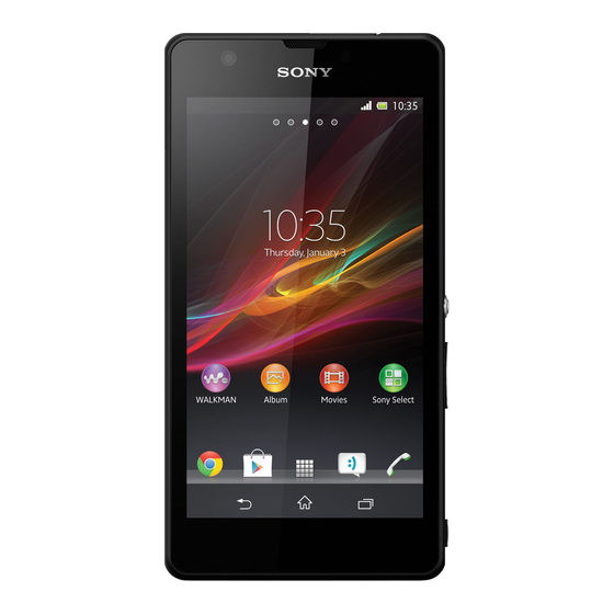
Sony Xperia ZR Working Instructions
Hide thumbs
Also See for Xperia ZR:
- User manual (136 pages) ,
- Troubleshooting manual (40 pages) ,
- Manual (10 pages)

Related Manuals for Sony Xperia ZR


Summary of Contents for Sony Xperia ZR
- Page 1 Working Instructions - mechanical - Xperia C5502, C5503 & M36h 1273-7033 Rev 1 Sony Mobile Communications AB – Company Internal...
-
Page 2: Table Of Contents
4.16 Card Connector Tray ................26 4.17 Cushion 2 MIC ................. 27 4.18 Cushion 3 x 3 mm ................28 4.19 Cushion 3 x 8 mm ................29 4.20 Cushion MIC ..................30 1273-7033 Rev 1 Sony Mobile Communications AB – Company Internal 2(71) - Page 3 5.9 Support Plate ..................68 5.10 Display ....................69 5.11 Sheet FPC Relay ................. 70 5.12 Battery 2300 mAh BA950 ..............70 5.13 Cover Battery ..................70 Revision History ................71 1273-7033 Rev 1 Sony Mobile Communications AB – Company Internal 3(71)
- Page 4 Working Instruction (mech) For general information about mechanical repair related issues, refer to 1220-1333: Generic Repair Manual - mechanical 1273-7033 Rev 1 Sony Mobile Communications AB – Company Internal 4(71)
-
Page 5: Exterior Views
Working Instruction (mech) Exterior Views 1273-7033 Rev 1 Sony Mobile Communications AB – Company Internal 5(71) -
Page 6: Tools
11. Bottom Press Inlay 12. Side Panel press 13. Side Panel Press Pad 14. Nylon pointer For part not on the tools above, refer to the ‘Tools Catalogue/Matrix’! 1273-7033 Rev 1 Sony Mobile Communications AB – Company Internal 6(71) -
Page 7: Disassembly
10. Lightguide Sheet 11. Sheet Battery Side 12. Holder Side Keys 13. FPC Relay Assy* 14. Cover Main Assy* *) Assy and Unit is used when several parts are handled 1273-7033 Rev 1 Sony Mobile Communications AB – Company Internal 7(71) -
Page 8: Cover Battery
Working Instruction (mech) Disassembly Cover Battery Open the Cover Battery, bottom side first. Battery 2300 mAh BA950 Remove Battery, bottom side first. 1273-7033 Rev 1 Sony Mobile Communications AB – Company Internal 8(71) -
Page 9: Sheet Fpc Relay
Use a Flex Film Assembly Tool to grab the Sheet FPC Relay in the upper left corner. Do not damage the FPC beneath! Gently peel of the Sheet FPC Relay! Scrap! Not to be reused! 1273-7033 Rev 1 Sony Mobile Communications AB – Company Internal 9(71) -
Page 10: Display
Working Instruction (mech) Disassembly Display Use the “Disassembly Machine” (1276-0592) and follow the associated instruction. The Disassembly Machine must be used when removing the Display! 1273-7033 Rev 1 Sony Mobile Communications AB – Company Internal 10(71) -
Page 11: Support Plate
Do not damage the Cover Main! When the all the adhesive is loosened, lift the long side of the Support Plate to make it free from the Cover Main. 1273-7033 Rev 1 Sony Mobile Communications AB – Company Internal 11(71) - Page 12 Working Instruction (mech) Disassembly: Support Plate Move the Support Plate in the arrows direction to free it from the Cover Main. 1273-7033 Rev 1 Sony Mobile Communications AB – Company Internal 12(71)
-
Page 13: Camera
Open the ZIF connector with the Front Opening Tool. Use a Flex Film Assembly Tool to remove the Camera by lifting it out from its cavity. Do not damage the Camera! 1273-7033 Rev 1 Sony Mobile Communications AB – Company Internal 13(71) -
Page 14: Main Pba
Gently loosen the connector on the RF Coax Cable from the Main PBA with your fingers. Use a Dentist Hook to loosen the Man PBA from its cavity. 1273-7033 Rev 1 Sony Mobile Communications AB – Company Internal 14(71) - Page 15 Do not damage the Main PBA! Lift the Main PBA to free it from the FPC’s before removing it by moving the Main PBA in the arrows direction. Do not damage the FPC’s! 1273-7033 Rev 1 Sony Mobile Communications AB – Company Internal 15(71)
-
Page 16: Rf Coax Cable
Gently lift the Lightguide from its cavity with your fingers. 3.10 Lightguide Sheet Gently lift the Lightguide Sheet from its cavity with a Flex Film Assembly Tool. Scrap, not to be reused! 1273-7033 Rev 1 Sony Mobile Communications AB – Company Internal 16(71) -
Page 17: Sheet Battery Side
Use a Dentist Hook to remove the Sheet Battery Side. Scrap, not to be reused! 3.12 Holder Side Keys Remove the Holder Side Keys with your fingers. Scrap, not to be reused! 1273-7033 Rev 1 Sony Mobile Communications AB – Company Internal 17(71) -
Page 18: Fpc Relay Assy
Use a Flex Film Assembly Tool to completely loosen the FPC Relay Assy from the Cover Main. Scrap, not to be reused! Be careful not to damage the FPC or the components on the FPC underneath. 1273-7033 Rev 1 Sony Mobile Communications AB – Company Internal 18(71) -
Page 19: Replacement
Prepare a new Sheet FPC Relay. Follow the 5.11 – 5.13 Reassembly instructions! Display Follow the 3.1 – 3.4 Disassembly instructions! Prepare a new Display. Follow the 5.10 – 5.13 Reassembly instructions! 1273-7033 Rev 1 Sony Mobile Communications AB – Company Internal 19(71) -
Page 20: Support Plate
Follow the 3.1 – 3.7 Disassembly instructions! Follow the 4.25 Removal instructions! Prepare a new Main PBA. Follow the 4.25 Reassembly instructions! 7 – Follow the 5. 5.13 Reassembly instructions! 1273-7033 Rev 1 Sony Mobile Communications AB – Company Internal 20(71) -
Page 21: Rf Coax Cable
Lift the RF Coax Cable from the Cover Main INSTALLATION Insert the RF Coax Cable into the Cover Main. Secure that the RF Coax Cable have snapped into place! 1273-7033 Rev 1 Sony Mobile Communications AB – Company Internal 21(71) -
Page 22: Lightguide
Follow the 3.1 – 3.2 and 3.11 – 3.12 Disassembly instructions! Prepare a new Holder Side Keys! Follow the 5.2 – 5.3 and 5.12 – 5.13 Reassembly instructions! 1273-7033 Rev 1 Sony Mobile Communications AB – Company Internal 22(71) -
Page 23: Fpc Relay
Gently loosen the connector on the RF Coax Cable from the PBA Antenna with your fingers. INSTALLATION Attach the lower part of the RF Coax Cable on to the PBA Antenna. Secure the position with your fingers! 1273-7033 Rev 1 Sony Mobile Communications AB – Company Internal 23(71) - Page 24 Working Instruction (mech) Replacement Attach the BtB from the FPC Relay to Main PBA. 1273-7033 Rev 1 Sony Mobile Communications AB – Company Internal 24(71)
-
Page 25: Cover Main
Scrap Adhesive Display, not to be reused! Remove and clean any remaining adhesive residue found on Display and Cover Main! Prepare a new Adhesive Display. – Follow the 5.10 5.13 Reassembly instructions! 1273-7033 Rev 1 Sony Mobile Communications AB – Company Internal 25(71) -
Page 26: Card Connector Tray
REMOVAL Use your fingers to pull the Card Connector Tray out from SIM Card Holder INSTALLATION Use your fingers to mount the Care Connector Tray according to picture. 1273-7033 Rev 1 Sony Mobile Communications AB – Company Internal 26(71) -
Page 27: Cushion 2 Nd Mic
Scrap Cushion 2 MIC, not to be reused! INSTALLATION Place the Cushion 2 MIC at the FPC PBA NFC according on PBA to marking Secure the position with your fingers! 1273-7033 Rev 1 Sony Mobile Communications AB – Company Internal 27(71) -
Page 28: Cushion 3 X 3 Mm
Scrap Cushion 3 x 3, not to be reused! INSTALLATION Place the Cushion 3 x 3 mm at the FPC PBA NFC according to marking on PBA. Secure the position with your fingers! 1273-7033 Rev 1 Sony Mobile Communications AB – Company Internal 28(71) -
Page 29: Cushion 3 X 8 Mm
Scrap Cushion 3 x 8, not to be reused! INSTALLATION Place the Cushion 3 x 8 mm at the FPC PBA NFC on PBA according to marking Secure the position with your fingers! 1273-7033 Rev 1 Sony Mobile Communications AB – Company Internal 29(71) -
Page 30: Cushion Mic
Scrap Cushion MIC, not to be reused! INSTALLATION Attach a new Cushion MIC with your fingers to the Cover Main according to the picture. Use the liner as guidance. 1273-7033 Rev 1 Sony Mobile Communications AB – Company Internal 30(71) -
Page 31: Cushion Window
Relay Assy guided by the 2 green lines according to the picture. Secure the position with your fingers! Make sure that the Cushion Window is free from the Lightguide and the Lightguide Sheet! 1273-7033 Rev 1 Sony Mobile Communications AB – Company Internal 31(71) -
Page 32: Fpc Pba Nfc
Be careful not to damage the FPC PBA NFC! INSTALLATION Insert the FPC PBA NFC in the lower (1) part first before lowering the upper part (2) down into position with your fingers. 1273-7033 Rev 1 Sony Mobile Communications AB – Company Internal 32(71) -
Page 33: Fpc Top Compl
Make sure that you only push on the rubber part! Now you can move the complete FPC Top Compl slightly forward (1) and out from its cavity (2) in the Cover Main. 1273-7033 Rev 1 Sony Mobile Communications AB – Company Internal 33(71) - Page 34 Use your fingers to slide the top part of the FPC Compl into its cavity. Make sure that the lower part of the FPC Top Compl snaps into place in the Cover Main! 1273-7033 Rev 1 Sony Mobile Communications AB – Company Internal 34(71)
-
Page 35: Gasket 2 Nd Mic
Peel of the from the Cover Main. Gasket 2 Scrap Gasket 2 MIC, not to be reused! INSTALLATION Attach the to the Cover Main according Gasket 2 to the picture. 1273-7033 Rev 1 Sony Mobile Communications AB – Company Internal 35(71) -
Page 36: Gasket Chat Camera
Be careful not to touch the lens of the Chat Camera! INSTALLATION Mount the to the Chat Camera on Gasket Chat Camera Be careful not to touch the lens of the Chat Camera! 1273-7033 Rev 1 Sony Mobile Communications AB – Company Internal 36(71) -
Page 37: Gasket Key
Make sure that the Gasket Key is completely in the aimed cavity by securing its position with your fingers! This is very important for a good feeling on the button! 1273-7033 Rev 1 Sony Mobile Communications AB – Company Internal 37(71) -
Page 38: Gasket Key Cam
Make sure that the Gasket Key Cam is completely in the aimed cavity by securing its position with your fingers! This is very important for a good feeling on the button! 1273-7033 Rev 1 Sony Mobile Communications AB – Company Internal 38(71) -
Page 39: Key Camera
Follow the 5.12 – 5.13 Reassembly instructions! REMOVAL Gently remove the Key Camera with your fingers. INSTALLATION Place the Key Camera at the correct position according to picture. 1273-7033 Rev 1 Sony Mobile Communications AB – Company Internal 39(71) -
Page 40: Key Power
Follow the 5.12 – 5.13 Reassembly instructions! REMOVAL Gently remove the Key Power with your fingers. INSTALLATION Place the Key Power at the correct position according to picture. 1273-7033 Rev 1 Sony Mobile Communications AB – Company Internal 40(71) -
Page 41: Key Volume
Follow the 5.12 – 5.13 Reassembly instructions! REMOVAL Gently remove the Key Volume with your fingers. INSTALLATION Place the Key Volume at the correct position according to picture. 1273-7033 Rev 1 Sony Mobile Communications AB – Company Internal 41(71) -
Page 42: Label Mobile Phone
INSTALLATION Check that the proper label format is loaded in the Zebra printer and write a new Label by using the ‘LabelMake’ software. One label only is allowed! 1273-7033 Rev 1 Sony Mobile Communications AB – Company Internal 42(71) -
Page 43: Loudspeaker & Adhesive Speaker
Remove and clean any remaining adhesive residue found on Cover Main! INSTALLATION Place the new Adhesive Speaker and new Loudspeaker in the cavity. Use the Generic Press Clamp 45N to fixate it for 10s! 1273-7033 Rev 1 Sony Mobile Communications AB – Company Internal 43(71) -
Page 44: Net Speaker
Main and use a non sharp Nylon Pointer to add some extra force on the outer edge of the Net Speaker to secure that the adhesive is activated. Be careful not to scratch the Net Speaker! 1273-7033 Rev 1 Sony Mobile Communications AB – Company Internal 44(71) -
Page 45: Nut
Place the Nut in place guided by the chamfering as reference. Secure the Nut by a new Screw 2.2. Use Bits (JCIS No 0 12 ± 2 Ncm torque). 1273-7033 Rev 1 Sony Mobile Communications AB – Company Internal 45(71) -
Page 46: Panel Key Power & Adhesive Panel Key Power
Cover Main! INSTALLATION Place the Adhesive Panel Key Power at the correct position according to picture before assemble the Panel Key Power. Secure its position with your fingers! 1273-7033 Rev 1 Sony Mobile Communications AB – Company Internal 46(71) -
Page 47: Panel Side L
Scrap Panel Side L, not to be reused! Remove and clean any remaining adhesive residue found on Cover Main INSTALLATION Attach the Panel Side L according to picture. Secure its position with your fingers! 1273-7033 Rev 1 Sony Mobile Communications AB – Company Internal 47(71) -
Page 48: Panel Side R Bottom
Scrap Panel Side R Bottom, not to be reused! Remove and clean any remaining adhesive residue found on Cover Main! INSTALLATION Attach the Panel Side R Bottom according to picture. Secure its position with your fingers! 1273-7033 Rev 1 Sony Mobile Communications AB – Company Internal 48(71) -
Page 49: Panel Side R Top
Scrap Panel Side R Top, not to be reused! Remove and clean any remaining adhesive residue found on Cover Main! INSTALLATION Attach the Panel Side R Top according to picture. Secure its position with your fingers! 1273-7033 Rev 1 Sony Mobile Communications AB – Company Internal 49(71) -
Page 50: Pba Antenna & Adhesive Pba Antenna
Make sure that no Adhesive residues are left on either PBA Antenna or FPC Relay Assy! INSTALLATION Place the Adhesive PBA Antenna on the PBA Antenna according to picture. 1273-7033 Rev 1 Sony Mobile Communications AB – Company Internal 50(71) - Page 51 Replacement: PBA Antenna & Adhesive PBA Antenna Place the PBA Antenna according to picture guided by the two guiding pins and then lower it down to its cavity. 1273-7033 Rev 1 Sony Mobile Communications AB – Company Internal 51(71)
-
Page 52: Sheet Magnetic Nfc
Make sure that you don’t damage the FPC! Remove and clean any remaining adhesive residue found on Cover Main! INSTALLATION Place the new Sheet Magnetic on the Cover Main Assy according to picture. 1273-7033 Rev 1 Sony Mobile Communications AB – Company Internal 52(71) -
Page 53: Water Indicator
Scrap Water Indicator, not to be reused! Pos.1 INSTALLATION Place the new Water Indicator at the location marked on the picture guided by the shape of the surface on the Cover Main. 1273-7033 Rev 1 Sony Mobile Communications AB – Company Internal 53(71) - Page 54 Scrap Water Indicator, not to be reused! Pos.2 INSTALLATION Place the new Water Indicator at the location marked on the picture guided by the shape of the surface on the Cover Main. 1273-7033 Rev 1 Sony Mobile Communications AB – Company Internal 54(71)
- Page 55 Scrap Water Indicator, not to be reused! Pos.3 INSTALLATION Place the new Water Indicator at the location marked on the picture guided by the shape of the surface on the Cover Main. 1273-7033 Rev 1 Sony Mobile Communications AB – Company Internal 55(71)
-
Page 56: Washer Key Power
Remove the old WI Top by peeling it off with the Nylon Pointer. INSTALLATION Place the new WI Top at the location marked on the picture guided by the lines on the PBA Complete. 1273-7033 Rev 1 Sony Mobile Communications AB – Company Internal 56(71) -
Page 57: Board Swap - Replacement
4 minutes until system boot up has been completed. Please DO NOT move the phone during starting up until “Select Language” menu is shown on the display! After “Select Language” menu, turn off the phone. 1273-7033 Rev 1 Sony Mobile Communications AB – Company Internal 57(71) -
Page 58: Board Swap - Change Label
Working Instruction (mech) Replacement 4.44 Board Swap – Change Label CHANGE LABEL Follow the instructions in the Generic Repair Manual – Build swap for change of label. 1273-7033 Rev 1 Sony Mobile Communications AB – Company Internal 58(71) -
Page 59: Board Swap - Customize Of Software
Working Instruction (mech) Replacement 4.45 Board Swap – Customize of Software CUSTOMIZE OF SOFTWARE Follow the instructions in the Generic Repair Manual – Build swap for customization of the software. 1273-7033 Rev 1 Sony Mobile Communications AB – Company Internal 59(71) -
Page 60: Re-Assembly
10. Support Plate 11. Display 12. Sheet FPC Relay 13. Battery 2300 mAh BA950 14. Cover Battery *) Assy and Unit is used when several parts are handled 1273-7033 Rev 1 Sony Mobile Communications AB – Company Internal 60(71) -
Page 61: Fpc Relay Assy
Place the Cover Main Assy into its cavity in the Cover Main Align the FPC with the hole and steering pin. Secure it position by adding some extra force to the 3 places where the adhesive are. 1273-7033 Rev 1 Sony Mobile Communications AB – Company Internal 61(71) -
Page 62: Holder Side Keys
Working Instruction (mech) Re-Assembly Holder Side Keys Insert a new Holder Side Keys into the Cover Main. Secure that the Holder Side Keys have snapped into place! 1273-7033 Rev 1 Sony Mobile Communications AB – Company Internal 62(71) -
Page 63: Sheet Battery Side
Place it into its cavity on the FPC Relay Assy according to picture. Lightguide Prepare the Lightguide. Place it into its cavity on the FPC Relay Assy according to picture. 1273-7033 Rev 1 Sony Mobile Communications AB – Company Internal 63(71) -
Page 64: Rf Coax Cable
Secure that the RF Coax Cable have snapped into place! Attach the lower part of the RF Coax Cable on to the PBA Antenna. Secure the position with your fingers! 1273-7033 Rev 1 Sony Mobile Communications AB – Company Internal 64(71) -
Page 65: Main Pba
Attach the BtB from FPC Top Compl to the Main PBA. Secure the position with your fingers! Attach the BtB from FPC Relay to the Main PBA. Secure the position with your fingers! 1273-7033 Rev 1 Sony Mobile Communications AB – Company Internal 65(71) - Page 66 Working Instruction (mech) Re-Assembly: Main PBA Attach the BtB from FPC PBA NFC to the Main PBA. Secure the position with your fingers! 1273-7033 Rev 1 Sony Mobile Communications AB – Company Internal 66(71)
-
Page 67: Camera
Prepare the Camera. Use a Flex Film Assembly Tool to insert the Camera into the ZIF contact on the Main PBA. Lock the ZIF contact with your fingers. 1273-7033 Rev 1 Sony Mobile Communications AB – Company Internal 67(71) -
Page 68: Support Plate
Secure its position by with new Screws 5.0. Use Bits (JCIS No 0 12 ± 2 Ncm torque). Do not damage the components on the PBA Complete! 1273-7033 Rev 1 Sony Mobile Communications AB – Company Internal 68(71) -
Page 69: Display
Toothed Rack Press Instruction for use. Press it with a pressure value of 360N for ten seconds (pressure value is adjust from 480N because of the weight of the press fixture) 1273-7033 Rev 1 Sony Mobile Communications AB – Company Internal 69(71) -
Page 70: Sheet Fpc Relay
5.13 Cover Battery Assemble the Cover Battery to the Cover Main Assy. Secure that the Cover Battery is tight on all sides by firmly pressing it with your fingers! 1273-7033 Rev 1 Sony Mobile Communications AB – Company Internal 70(71) -
Page 71: Revision History
Working Instruction (mech) Revision History Rev. Date Changes / Comments 2013-June-13 First Release 1273-7033 Rev 1 Sony Mobile Communications AB – Company Internal 71(71)
Need help?
Do you have a question about the Xperia ZR and is the answer not in the manual?
Questions and answers