Table of Contents

Related Manuals for AES 3100S-PKG


Summary of Contents for AES 3100S-PKG
- Page 1 AES Solar Subscriber Installation, Operation and Programming Manual AES Corporation 285 Newbury Street Peabody, MA 01960 USA Tel (978) 535-7310 • Fax (978) 535-7313 www.aes-corp.com Copyright © 2022 AES Corp. All Rights Reserved pg. 1...
- Page 2 AES SOLAR Subscriber This page deliberately left blank AES P/N 40-3100S Rev. 3, 3/14/2023...
-
Page 3: Table Of Contents
Zone Input Options for Zones 1 though 4 ............... 18 Alarm Panel Siren Input Options for Zones 5 and 6 ..........19 6.10 Consecutive AT Events ....................19 6.11 Inverted Fire ........................19 6.12 Restoral ......................... 19 6.13 Status LED Indicators ..................... 20 AES P/N 40-3100S Rev. 3, 3/14/2023... - Page 4 Flexible Power Option ....................24 Reporting ........................28 Compatible Receiver ..................... 28 Testing .......................... 28 Maintenance ......................... 28 Troubleshooting ......................28 Repair Information ......................29 Contact Information ...................... 29 Battery Replacement Instructions .................. 29 Warranty ........................30 AES P/N 40-3100S Rev. 3, 3/14/2023...
- Page 5 7007S Solar Enclosure .................... 7 Figure 2. Earth Ground Connection Point ................9 Figure 3. Connecting the Battery Backup ................10 Figure 4. Antenna and Surge Suppressor Grounding............11 Figure 5. Earth Grounding ....................11 AES P/N 40-3100S Rev. 3, 3/14/2023...
-
Page 6: Safety Considerations
• AES assumes no responsibility for the equipment’s Periodically test the system for proper operation. failure to operate. AES's sole responsibility is to repair or replace any AES device found to be defective during the warranty period. • Avoid dropping or exposing the unit to physical impact that could damage the enclosure or internal components. -
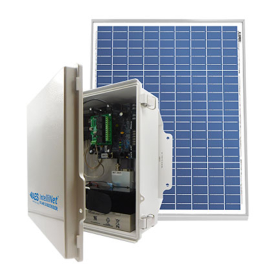
Page 7: Figure 1. 7007S Solar Enclosure
Transceiver • Output Power: 2 Watts • Frequency Range: 450–470 MHz standard (Contact AES for other UHF and VHF frequencies.) Access • Four each – field wiring, antenna, solar panel power, and vent. See drawing for locations. Figure 1. Model 3100S Solar Enclosure... -
Page 8: Pre-Installation
Weather Proofing Steps Important! Use AES supplied water resistant tape and grease to prevent water entering the enclosure. Apply this at each of the cable entries into the enclosure. AES P/N 40-3100S Rev. 3, 3/14/2023... -
Page 9: Wiring
AES SOLAR Subscriber 5. Wiring Earth Ground Connection Earth ground is provided with a terminal. See the lower left corner in Figure 2 below. Figure 2. Earth Ground Connection Point AES P/N 40-3100S Rev. 3, 3/14/2023... -
Page 10: Battery Connection
The SOLAR panel charges the battery using a charger controller. The battery voltage level conditions are: • Low Battery (Trouble message): 11.2 V DC or below • Subscriber Battery Disconnect: Below 10 V DC • Battery Reconnect (Restoral message): Above 12 V DC AES P/N 40-3100S Rev. 3, 3/14/2023... -
Page 11: Figure 4. Antenna And Surge Suppressor Grounding
AES SOLAR Subscriber A protective surge suppressor (AES Model 7230) option (separately purchased) may be installed in line with any type of remotely installed antenna, as shown in the diagram below. The surge suppressor and outdoor antenna must be earth grounded. -
Page 12: Programming
Place the cursor in the Current Password text box. Enter the current password. In the New Password text box, type the new password. Type the new password again in the Confirm box and click Change Password. AES P/N 40-3100S Rev. 3, 3/14/2023... -
Page 13: Solar Subscriber Interface
Configuration settings are made and changed using either the dropdown or slider switch controls in the window. The dropdown provides a list to select from: The slider switch provides one of two values to select: AES P/N 40-3100S Rev. 3, 3/14/2023... -
Page 14: Saving Configuration Changes
Select the System tab, as shown in the following figure: The version number is displayed in the System Firmware Upgrade section: SUBSCRIBER CONFIGURATION Subscriber ID Subscriber ID is set in the Configuration tab. From the main menu, select the Configuration tab. AES P/N 40-3100S Rev. 3, 3/14/2023... -
Page 15: Event Reporting Route
Subscriber IP Address under Advanced Configuration. • Internet and Radio Backup: • Central Receiver Configuration Advanced Configuration. and Subscriber IP Address under • Internet Only: Central Receiver Configuration Advanced Configuration. and Subscriber IP Address under AES P/N 40-3100S Rev. 3, 3/14/2023... -
Page 16: Radio Configuration
Valid values are 0000 to FFFF. Note: The code must match the AES 7170 IP-Link cipher code for the network that the subscriber is to join. The subscriber will not join the mesh network if the cipher code is incorrect. -
Page 17: Advanced Configuration
Time-to-Live settings are for managing the performance of the AES mesh network. TTL is the length of time a packet message transmission for a specific setting is retried by a subscriber in the AES mesh network. The subscriber will stop attempting to transmit the packet when the TTL limit has expired. -
Page 18: Zone Input Configuration
Supervised When the Fire Zones switch is set to Yes and Inverted Fire is set to Yes, then the Fire and Inverted Fire options will be listed in the dropdown options as shown below: AES P/N 40-3100S Rev. 3, 3/14/2023... -
Page 19: Alarm Panel Siren Input Options For Zones 5 And 6
(if Fire Zones = Yes). Set all unused zones to Bypassed. Do not install EOL resistors on Note: Bypassed zones. 6.12 RESTORAL Restoral messages are sent for the zone when the Restoral switch is set to Yes. AES P/N 40-3100S Rev. 3, 3/14/2023... -
Page 20: Status Led Indicators
Self-test failure (excluding low Steady/no blink battery and AC) Symbols as follows: "◼" = short blink, " " = long blink Period between patterns is about 1 second. The chart shows the pattern repeated 3 times. AES P/N 40-3100S Rev. 3, 3/14/2023... -
Page 21: Subscriber Status Check
Wired MAC – The Media Access Control (MAC) address (which is the physical address) is a unique network identifier assigned to the Model 3100S subscriber. • Wired IPv4 – The IP address of the subscriber. AES P/N 40-3100S Rev. 3, 3/14/2023... -
Page 22: Tools
The RF Antenna Test turns the transceiver transmitter on for approximately 5 seconds and allows use of RF test equipment, such as a SWR meter or power meter. This function allows you to check transceiver RF power output, coaxial cable connections, antenna tuning, and other parameters. AES P/N 40-3100S Rev. 3, 3/14/2023... -
Page 23: Ping
Add User allows you to add additional users to the system. To add a user: Enter the username into the “Username” field. Enter the password into the “Password” field. Re-enter the password again into the “Confirm” field. Add User When through, click the button. AES P/N 40-3100S Rev. 3, 3/14/2023... -
Page 24: Buzzer - Onboard Subscriber
Subscriber power can be provided by several different types of power sources. This control configures the type of power source and the features associated with the power source. From the Configuration tab, select the Flexible Power Option panel. AES P/N 40-3100S Rev. 3, 3/14/2023... - Page 25 Suppress Charger Fault Report: Set Suppress Charger Fault Report to Yes/No by clicking the Suppress Charger Fault Report switch. When changes are complete, click Save Changes. • Power from 24 V DC and Battery Wiring Refer to the section for supply and connection requirements. AES P/N 40-3100S Rev. 3, 3/14/2023...
- Page 26 Suppress Charger Fault Reporting: Set Suppress DC Charge Fault to Yes/No by clicking the Suppress Charger Fault Reporting switch. When done with changes, click the Save Changes button. • Power From 24 V DC only AES P/N 40-3100S Rev. 3, 3/14/2023...
- Page 27 Suppress DC Power Fault Set Suppress DC Power Fault to Yes No by clicking the Suppress DC Power Fault switch. When done with changes, click the Save Changes button. AES P/N 40-3100S Rev. 3, 3/14/2023...
-
Page 28: Reporting
9. Reporting COMPATIBLE RECEIVER The SOLAR Subscriber is compatible with the AES Corp. Model 7705i/7705ii MultiNet and INCC Receivers. 10. Testing Some of the tests to be performed at the installation site require a response from a person at the monitoring station: •... -
Page 29: Repair Information
Note: No user serviceable components are located on the circuit boards. Defective circuit board units must be returned Return Material to AES. For information on returning units, see the section at the end of the Warranty. 13. Repair Information The SOLAR Subscriber contains no user serviceable parts. -
Page 30: Warranty
Licensed Technology solely in connection with the use and operation of AES Products and for no other purpose or use whatsoever. No title or ownership in or to any such Licensed Technology is conveyed by the sale or delivery of any AES Products; all such rights are retained by AES.
Need help?
Do you have a question about the 3100S-PKG and is the answer not in the manual?
Questions and answers