Table of Contents
Advertisement
Quick Links
Radiocrafts
Embedded Wireless Solutions
RC2300DK/RC2301DK Demonstration Kit User Manual
Table of contents
TABLE OF CONTENTS ..........................................................................................................1
INTRODUCTION .....................................................................................................................2
DEMONSTRATION BOARD ...................................................................................................3
POWER SUPPLY SECTION ...................................................................................................4
RS-232 INTERFACE ...............................................................................................................5
CONNECTORS .......................................................................................................................6
PUSH BUTTONS.....................................................................................................................6
LEDS .......................................................................................................................................6
ACCELEROMETER ................................................................................................................6
POTENTIOMETER ..................................................................................................................7
LIGHT SENSOR ......................................................................................................................7
DEBUG AND PROGRAMMING INTERFACE .........................................................................8
I/O MAPPING ........................................................................................................................10
USING THE DEMONSTRATION KIT ....................................................................................11
SW IMPLEMENTATION ........................................................................................................11
CIRCUIT DIAGRAM ..............................................................................................................12
BILL OF MATERIALS ...........................................................................................................13
PCB LAYOUT........................................................................................................................14
TROUBLESHOOTING...........................................................................................................16
DOCUMENT REVISION HISTORY .......................................................................................17
DISCLAIMER.........................................................................................................................17
TRADEMARKS .....................................................................................................................17
LIFE SUPPORT POLICY.......................................................................................................17
CONTACT INFORMATION ...................................................................................................17
©2007 Radiocrafts AS
RC2300DK/RC2301DK Demonstration Kit User Manual (rev. 2.0)
RC2300DK/RC2301DK
Page 1 of 17
Advertisement
Table of Contents

Related Manuals for Radiocrafts RC2300DK


Summary of Contents for Radiocrafts RC2300DK
-
Page 1: Table Of Contents
SW IMPLEMENTATION ......................11 CIRCUIT DIAGRAM ......................12 BILL OF MATERIALS ......................13 PCB LAYOUT........................14 TROUBLESHOOTING......................16 DOCUMENT REVISION HISTORY ..................17 DISCLAIMER.........................17 TRADEMARKS ........................17 LIFE SUPPORT POLICY.......................17 CONTACT INFORMATION ....................17 ©2007 Radiocrafts AS RC2300DK/RC2301DK Demonstration Kit User Manual (rev. 2.0) Page 1 of 17... -
Page 2: Introduction
The RC2300DK Demonstration Kit is designed to make it easy for the user to evaluate the module and/or develop an application very quickly. With the RC2300DK Demonstration Kit you can: •... -
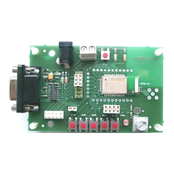
Page 3: Demonstration Board
Typical range measured between two boards in line-of-sight is 110 meters when the chip antennas are oriented vertically (or parallel). Indoors a range of 10-30 can be expected, depending on the materials in walls and floors. ©2007 Radiocrafts AS RC2300DK/RC2301DK Demonstration Kit User Manual (rev. 2.0) Page 3 of 17... -
Page 4: Power Supply Section
DC-jack into the board. If the VCC power-on rise-time specification is not met, the board may need the RESET to be activated to ensure correct start-up. ©2007 Radiocrafts AS RC2300DK/RC2301DK Demonstration Kit User Manual (rev. 2.0) Page 4 of 17... -
Page 5: Rs-232 Interface
Install jumper when using hardware handshake Ground Connect jumpers here for TXD and RXD Connect jumpers here for hardware handshake (CTS, RTS) Figure 3. RS232 driver interface (Photo to be updated!) ©2007 Radiocrafts AS RC2300DK/RC2301DK Demonstration Kit User Manual (rev. 2.0) Page 5 of 17... -
Page 6: Connectors
T1 to ground. The accelerometer has a 20 ms start-up time after power on. See the Analog Devices ADXL321 datasheet for details about the accelerometer. ©2007 Radiocrafts AS RC2300DK/RC2301DK Demonstration Kit User Manual (rev. 2.0) Page 6 of 17... -
Page 7: Potentiometer
(light) to 20M (dark), and is connected a voltage divider together with a 200k Ohm resistor to the supply voltage. See the Silonex NSL-19M51 datasheet for details about the LDR. ©2007 Radiocrafts AS RC2300DK/RC2301DK Demonstration Kit User Manual (rev. 2.0) Page 7 of 17... -
Page 8: Debug And Programming Interface
Debug Data (DD) CSn (optional) SCL (optional) RESET_N MOSI (optional) NC (not connected) MISO (optional) Below is shown how to connect the RC2300DB to the SmartRF04EB. ©2007 Radiocrafts AS RC2300DK/RC2301DK Demonstration Kit User Manual (rev. 2.0) Page 8 of 17... - Page 9 Radiocrafts Embedded Wireless Solutions RC2300DK/RC2301DK Figure 4. Programming interface connection from SmartRF04EB (Texas Instruments) Figure 5. Programming interface connection from FlashPro-CC ©2007 Radiocrafts AS RC2300DK/RC2301DK Demonstration Kit User Manual (rev. 2.0) Page 9 of 17...
-
Page 10: I/O Mapping
Debug data Debug data P2.2 Debug Clock Debug Clock RESET S7 push button, RESET. Pressing RESET this button will activate the main RESET of the module ©2007 Radiocrafts AS RC2300DK/RC2301DK Demonstration Kit User Manual (rev. 2.0) Page 10 of 17... -
Page 11: Using The Demonstration Kit
I/Os of the modules. Important: The use of radio transceivers is regulated by international and national rules. Radiocrafts’ modules meet the regulations in EU and US/Canada for different frequency variants. Make sure the local regulative are according to these rules. Your local telecommunication authorities can provide more information on use of un-licensed radio transmitter in your country. -
Page 12: Circuit Diagram
Radiocrafts Embedded Wireless Solutions RC2300DK/RC2301DK Circuit Diagram The circuit diagram is shown below. A full resolution schematic is found in RC2300DB_1_0.zip (available from Radiocrafts’ website). ©2007 Radiocrafts AS RC2300DK/RC2301DK Demonstration Kit User Manual (rev. 2.0) Page 12 of 17... -
Page 13: Bill Of Materials
Resistor, 0603 72PTR10K Trimming pot, 10K, knob S1-5, S7 PUSH_BUTTON Push button, SMD MAX3232 RS-232 Transceiver, SO-16 LP2980-3.0V 3.0V low drop-out regulator ADXL321 Dual-axis Accelerometer, QFN ©2007 Radiocrafts AS RC2300DK/RC2301DK Demonstration Kit User Manual (rev. 2.0) Page 13 of 17... -
Page 14: Pcb Layout
FR-4 board material. The PCB is 1.6mm thick. Full resolution layout and assembly drawing are found in RC2300DB_1_0.zip. Figure 6. RC2300DB PCB layout, top layer (1) Figure 7. RC2300DB PCB layout, bottom layer (2) ©2007 Radiocrafts AS RC2300DK/RC2301DK Demonstration Kit User Manual (rev. 2.0) Page 14 of 17... - Page 15 Radiocrafts Embedded Wireless Solutions RC2300DK/RC2301DK Figure 8. RC2300DB PCB component placement, top side ©2007 Radiocrafts AS RC2300DK/RC2301DK Demonstration Kit User Manual (rev. 2.0) Page 15 of 17...
-
Page 16: Troubleshooting
Make sure the PC (or host) is configured for the correct serial port • Make sure the PC serial port settings are correct with respect to baud rate, data bits, stop bits, parity bits and handshake ©2007 Radiocrafts AS RC2300DK/RC2301DK Demonstration Kit User Manual (rev. 2.0) Page 16 of 17... -
Page 17: Document Revision History
Radiocrafts AS customers using or selling these products for use in such applications do so at their own risk and agree to fully indemnify Radiocrafts AS for any damages resulting from any improper use or sale.
Need help?
Do you have a question about the RC2300DK and is the answer not in the manual?
Questions and answers