Advertisement
DESCRIPTION
Demonstration circuit 2268A-I is a high efficiency, high
density, dual 8A, switch mode step-down power supply on
a compact 1.5' × 1.2' PCB. It features the
μModule
regulator. The input voltage is from 4.5V to
®
16V. The output voltage is programmable from 0.6V to
5.3V. DC2268A-I can deliver up to 25A maximum in each
channel. As explained in the data sheet, output current
derating is necessary for certain V
conditions. The board operates in continuous conduc-
tion mode in heavy load conditions. For high efficiency
at low load currents, the resistor jumper (R1/R2) selects
pulse-skipping mode for noise sensitive applications or
Burst-Mode
in less noise sensitive applications. Two out-
®
puts can be connected in parallel for a single 50A output
solution with optional jumper resistors. The board allows
the user to program how its output ramps up and down
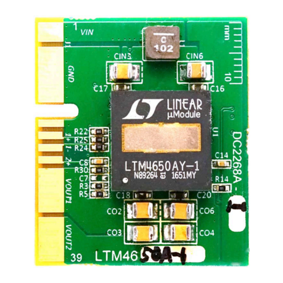
BOARD PHOTO
LTM
4650A-1
®
, V
, and thermal
IN
OUT
Figure 1. LTM4650A-1/DC2268A-I Demo Board
DEMO MANUAL DC2268A-I
Dual 25A or Single 50A
μModule Regulator
through the TRACK/SS pin. Remote output voltage sens-
ing is available for improved output voltage regulation
at the load point. An optional input inductor L1 reduces
the EMI noise for noise sensitive applications. DC2268A
can be easily inserted to an edge connector for testing
and debugging. These features and the availability of the
LTM4650A-1 in a compact 16mm × 16mm × 4.41mm
LGA package make it ideal for use in many high-density
point-of-load regulation applications. The LTM4650A-1
data sheet must be read in conjunction with this demo
manual for working on or modifying the DC2268A-I.
Design files for this circuit board are available at
http://www.linear.com/demo/DC2268A-I
L, LT, LTC, LTM, Linear Technology, the Linear logo, µModule and Burst Mode are registered
trademarks of Analog Devices, Inc. All other trademarks are the property of their respective
owners.
LTM4650A-1
dc2268aif
1
Advertisement
Table of Contents

Related Manuals for Linear Technology DC2268A-1


Summary of Contents for Linear Technology DC2268A-1
- Page 1 50A output L, LT, LTC, LTM, Linear Technology, the Linear logo, µModule and Burst Mode are registered solution with optional jumper resistors. The board allows trademarks of Analog Devices, Inc. All other trademarks are the property of their respective owners.
- Page 2 DEMO MANUAL DC2268A-I PERFORMANCE SUMMARY Specifications are at T = 25°C Table 1. PARAMETER CONDITIONS VALUE Input Voltage Range 4.5V ~ 16V Output Voltage V = 4.5~16V, I = 0A ~25A 3.3V ± 1.5% OUT1 OUT1 Output Voltage V = 4.5~16V, I = 0A ~25A 1.5V ±...
- Page 3 DEMO MANUAL DC2268A-I QUICK START PROCEDURE Figure 2. Test Setup of DC2268A-I = 12V = 12V = 5V = 5V (LOAD CURRENT) (LOAD CURRENT) 2268ai F03 2268ai F04 Figure 3. Measured Efficiency on Channel 1 (V = 3.3V, Figure 4. Measured Efficiency on Channel 2 (V = 1.5V, OUT1 OUT2...
- Page 4 DEMO MANUAL DC2268A-I QUICK START PROCEDURE Figure 5. Measured Channel 1 12.5A to 18.75A Load Transient (V = 12V, V = 3.3V) OUT1 Figure 6. Measured Channel 12.5A to 18.75A Load Transient (V = 12V, V = 1.5V) OUT2 dc2268aif...
- Page 5 DEMO MANUAL DC2268A-I QUICK START PROCEDURE Figure 7. Thermal Performance at V = 12V, V = 3.3V/11A, V = 1.5V/11A, OUT1 OUT2 = 600kHz, T = 23°C, No Forced Airflow Figure 8. Thermal Performance at V = 12V, V = 3.3V/19A, V = 1.5V/19A, OUT1 OUT2...
- Page 6 DEMO MANUAL DC2268A-I PARTS LIST ITEM REFERENCE PART DESCRIPTION MANUFACTURER/PART NUMBER Required Circuit Components CIN1, CIN2, CIN3, CIN4, CIN5, CIN6 CAP , 1210 22µF 10% 25V X5R AVX 12103D226KAT2A CO1, CO5 CAP , 7343 470µF 20% 6.3V POSCAP PANASONIC 6TPF470MAH CO2, CO3, CO4, CO6 CAP , 1210 100µF 10% 6.3V X5R AVX 12106D107KAT2A...
- Page 7 Information furnished by Linear Technology Corporation is believed to be accurate and reliable. However, no responsibility is assumed for its use. Linear Technology Corporation makes no representa- tion that the interconnection of its circuits as described herein will not infringe on existing patent rights.
- Page 8 Linear Technology Corporation (LTC) provides the enclosed product(s) under the following AS IS conditions: This demonstration board (DEMO BOARD) kit being sold or provided by Linear Technology is intended for use for ENGINEERING DEVELOPMENT OR EVALUATION PURPOSES ONLY and is not provided by LTC for commercial use. As such, the DEMO BOARD herein may not be complete in terms of required design-, marketing-, and/or manufacturing-related protective considerations, including but not limited to product safety measures typically found in finished commercial goods.
Need help?
Do you have a question about the DC2268A-1 and is the answer not in the manual?
Questions and answers