
Related Manuals for Axiom NXP TWR-S12G128-KIT


Summary of Contents for Axiom NXP TWR-S12G128-KIT
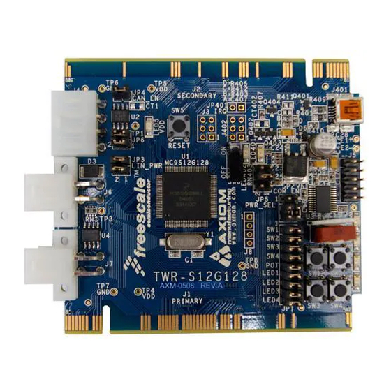
- Page 1 D O C - 0 5 0 8 - 0 1 0 , R E V TWR-S12G128 Demonstration Board for Freescale MC9S12G128 Microcontroller USER GUIDE www.axman.com Web Site: support@axman.com Support:...
-
Page 2: Table Of Contents
T W R - 9 S 1 2 G 1 2 8 J U N E 2 0 1 0 U S E R G U I D E CONTENTS CAUTIONARY NOTES ......................4 TERMINOLOGY ......................... 4 FEATURES ..........................5 MEMORY MAP .......................... - Page 3 T W R - 9 S 1 2 G 1 2 8 J U N E 2 0 1 0 U S E R G U I D E FIGURES Figure 1: Memory Map........................ 6 Figure 2: BDM_PORT Header ....................8 Figure 3: PWR_SEL Option Header ...................
-
Page 4: Cautionary Notes
1) Electrostatic Discharge (ESD) prevention measures should be used when handling this product. ESD damage is not a warranty repair item. 2) Axiom Manufacturing does not assume any liability arising out of the application or use of any product or circuit described herein; neither does it convey any license under patent rights or the rights of others. -
Page 5: Features
T W R - 9 S 1 2 G 1 2 8 J U N E 2 0 1 0 U S E R G U I D E FEATURES The TWR-S12G128 is a demonstration board for the MC9S12G128 microcontroller; an automotive, 16-bit microcontroller focused on low-cost, high-performance in a low pin-count device. -
Page 6: Memory Map
T W R - 9 S 1 2 G 1 2 8 J U N E 2 0 1 0 U S E R G U I D E MEMORY MAP Figure 1 below shows the target device memory map. Refer to the MC9S12G128 Reference Manual (RM) for further information. -
Page 7: Software Development
T W R - 9 S 1 2 G 1 2 8 J U N E 2 0 1 0 U S E R G U I D E SOFTWARE DEVELOPMENT Software development requires the use of a compiler or an assembler supporting the HCS12(X) instruction set and a host PC running a debug interface. -
Page 8: Osbdm Bootloader
T W R - 9 S 1 2 G 1 2 8 J U N E 2 0 1 0 U S E R G U I D E CAUTION: When powered from the USB bus, do not exceed the 500mA maximum allowable current drain. -
Page 9: Power Select
T W R - 9 S 1 2 G 1 2 8 J U N E 2 0 1 0 U S E R G U I D E connecting external power to the board if desired. An on-board regulator is used to create the board operating voltage from this input. -
Page 10: Timing
T W R - 9 S 1 2 G 1 2 8 J U N E 2 0 1 0 U S E R G U I D E TIMING The TWR-S12G128 internal timing source is active from RESET by default. An external 8MHz crystal oscillator, configured for low-power operation, is also installed. -
Page 11: Com Connectcor
T W R - 9 S 1 2 G 1 2 8 J U N E 2 0 1 0 U S E R G U I D E COM Connectcor A 2x5, 0.1”, standard “Berg” pin-header provides external connections for the SCI port. Figure 5 below shows the COM1 pin-out. -
Page 12: Lin Enable
T W R - 9 S 1 2 G 1 2 8 J U N E 2 0 1 0 U S E R G U I D E The LIN interface provides optional features of slew rate control, network supply, and wake up option. -
Page 13: Lin-J1 Connector
T W R - 9 S 1 2 G 1 2 8 J U N E 2 0 1 0 U S E R G U I D E Figure 8: JP6 Option Header ● ● JP3 Connects LIN bus to +V input (default) ●... -
Page 14: Can Termination Enable
T W R - 9 S 1 2 G 1 2 8 J U N E 2 0 1 0 U S E R G U I D E NOTE: CAN Port Connector – Molex 39-30-3045 Mates with; Housing – Molex 39-01-4040, Pin – Molex 39-00-0217 CAN Termination Enable CAN bus termination of 120 ohm with virtual ground is applied to the differential CAN signals on both channels. -
Page 15: User Led's
T W R - 9 S 1 2 G 1 2 8 J U N E 2 0 1 0 U S E R G U I D E User LED’s The TWR-S12G128 target board applies 4, green, LEDs for output indication. Each LED is configured for active-low operation. -
Page 16: Edge Connector Pinout
T W R - 9 S 1 2 G 1 2 8 J U N E 2 0 1 0 U S E R G U I D E EDGE CONNECTOR PINOUT The TWR-S12 board connects to the Freescale Tower System using the 2 PCIe Edge Connectors. - Page 17 T W R - 9 S 1 2 G 1 2 8 J U N E 2 0 1 0 U S E R G U I D E 3.3V Power 3.3V Power Pri_B36 Pri_A36 Pri_B37 Pri_A37 PWM7/KWP7/PP7 PWM3/ETRIG3/KWP3/PP3 Pri_B38 Pri_A38 PWM6/KWP6/PP6 PWM2/ETRIG2/KWP2/PP2...
-
Page 18: Figure 14: Secondary Edge Connector
T W R - 9 S 1 2 G 1 2 8 J U N E 2 0 1 0 U S E R G U I D E Figure 14: Secondary Edge Connector 5.0V Power Sec_B01 Sec_A01 5.0V Power Ground Sec_B02 Sec_A02... - Page 19 T W R - 9 S 1 2 G 1 2 8 J U N E 2 0 1 0 U S E R G U I D E Sec_B46 Sec_A46 Sec_B47 Sec_A47 Sec_B48 Sec_A48 Ground Sec_B49 Sec_A49 Ground Sec_B50 Sec_A50 Sec_B51 Sec_A51...
Need help?
Do you have a question about the NXP TWR-S12G128-KIT and is the answer not in the manual?
Questions and answers