Table of Contents

Subscribe to Our Youtube Channel
Related Manuals for Axiom CME-12B


Summary of Contents for Axiom CME-12B
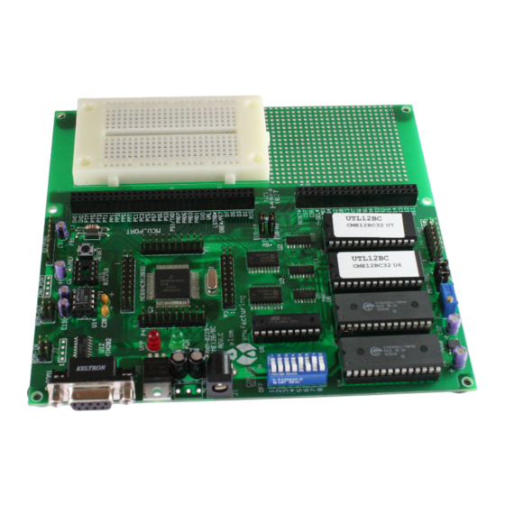
- Page 1 CME-12B/BC Development Board for Motorola 68HC12B32 and 68HC12BC32 Microcontrollers xiom anufacturing ™ © 2000 2813 Industrial Ln. • Garland, TX 75041 • (972) 926-9303 FAX (972) 926-6063 email: Gary@axman.com • web: http://www.axman.com...
-
Page 2: Table Of Contents
CONTENTS CONTENTS GETTING STARTED ....................3 Installing the Software..............3 Board Startup .................. 3 Support Software ................4 Software Development ..............4 TUTORIAL......................5 Creating source code ..............5 Assembling source code ..............6 Running your application ..............7 Programming Flash EEPROM............8 MEMORY MAP .....................9 CONFIG SWITCH....................10 MEM-SEL JUMPERS ..................10... -
Page 3: Getting Started
Follow the steps in this section to get started quickly and verify everything is working correctly. Installing the Software 1. Insert the Axiom 68HC12 support disk in your PC. If the setup program does not start, run the file called "SETUP.EXE" on the disk. -
Page 4: Support Software
There are many useful programs and documents on the included HC12 support disk that can make developing projects on the CME-12B/BC easier. You should browse the disk and copy anything you want to your hard drive. See the README.TXT file for a description of what is included. -
Page 5: Tutorial
"Hello World" to the serial port. Creating source code You can write source code for the CME-12B/BC board using any language that compiles to Motorola 68HC12 instructions. Included on the software disk is a free Assembler and also a freeware C compiler and Basic compiler. -
Page 6: Assembling Source Code
Assembling source code An example program called “HELLO.ASM” is provided under the \EXAMPLE directory. You can assemble your source code using command line tools under a DOS prompt by typing: AS12 HELLO.ASM –LHELLO Most compilers and assemblers allow many command line options so using a MAKE utility or batch file is recommended if you use this method. -
Page 7: Running Your Application
The provided example “HELLO.ASM” was created to run from RAM so you can use the D- Bug12 Monitor to test it without programming it into EEPROM. If you haven’t done so already, verify that the CME-12B/BC board is connected and operating properly by following the steps under “GETTING STARTED” until you see the D-Bug12 prompt, then follow these steps to run your program: 1. -
Page 8: Programming Flash Eeprom
Programming Flash EEPROM You can program your application into EEPROM so it executes automatically when you apply power to the board as follows: 1. Make a backup copy of HELLO.ASM then use a text editor to modify it. Change the start of the program to $8000 which is the beginning of the EEPROM. -
Page 9: Memory Map
MEMORY MAP Following is the default memory map for this development board. Consult the HC12 technical reference manual on the support disk for details of the internal memory map for the processor. FFFF RESET Vector Address FFFE CONFIG SWITCH 1 ON ON ON ON External EPROM U6/7 (Debug12) ON ON ON OFF... -
Page 10: Config Switch
CONFIG SWITCH The CME-12B/BC board is shipped from the manufacturer with the following default CONFIG SWITCH settings: The 8 position CONFIG SWITCH provides an easy method of configuring the CME-12B/BC32 board operation. Following are the configuration switch descriptions and HC12 I/O port... -
Page 11: Ports And Connectors
PORTS AND CONNECTORS LCD_PORT The LCD_PORT interface is connected to the data bus and memory mapped to locations 270 – 27F hex assigned to CS7. For the standard display, address 270 is the Command register, address 271 is the Data register. The interface supports all OPTREX™... -
Page 12: Mcu_Port
MCU_PORT The MCU_PORT provides access to the peripheral features and I/O lines of the HC12 as follows: D0 – D7 Low Byte of the Data Bus in Wide Expanded Mode. Port B in Single Chip Mode. /XIRQ HC12 XIRQ interrupt input . 9 10 D7 VFP Programming voltage, 12v, when VPP_EN jumper is /XIRQ 11 12 /DBE... -
Page 13: Com1 Serial Port
COM1 SERIAL PORT The COM-1 port has a Female DB9 connector that interfaces to TXD0 2 6 the HC12 internal SCI0 serial port. It uses a simple 2 wire RXD0 3 7 asynchronous serial interface. GND 5 9 Pins 1, 4, and 6 are connected for default handshake standards. Pins 7 and 8 are connected for default handshake standards. -
Page 14: Bdm-In
BDM-IN The BDM-IN port is a 6 pin header compatible in pinout with the Motorola Background Debug Mode (BDM) Pod. This allows the connection of a background debugger for software development, programming and debugging in real-time, since the BDM control logic does not reside in the CPU. -
Page 15: Troubleshooting
TROUBLESHOOTING TROUBLESHOOTING The CME-12B/BC board is fully tested and operational before shipping. If it fails to function properly, inspect the board for obvious physical damage first. Ensure that all IC devices in sockets are properly seated. Verify the communications setup as described under GETTING STARTED and see the Tips and Suggestions sections following for more information. -
Page 16: Code Execution
Tips and Suggestions Following are a number of tips, suggestions and answers to common questions that will solve many problems users have with the CME-12B/BC development system. You can download the latest software from the Support section of our web page at: www.axman.com... -
Page 17: Tables
TABLES TABLE 1. LCD Command Codes Command codes are used for LCD setup and control of character and cursor position. All command codes are written to LCD panel address $B5F0. The BUSY flag (bit 7) should be tested before any command updates to verify that any previous command is completed. A read of the command address $B5F0 will return the BUSY flag status and the current display character location address. - Page 18 TABLE 3. D-Bug12 Monitor Commands ASM <Address> Single line assembler/disassembler <CR> Disassemble next instruction <.> Exit assembly/disassembly BAUD <baudrate> Set communications rate for the terminal BF <StartAddress> <EndAddress> Fill memory with data [<data>] BR [<Address>] Set/Display user breakpoints BULK Erase entire on-chip EEPROM contents CALL [<Address>] Call user subroutine at <Address>...
Need help?
Do you have a question about the CME-12B and is the answer not in the manual?
Questions and answers