
Subscribe to Our Youtube Channel
Related Manuals for Axiom CML12S-DP256


Summary of Contents for Axiom CML12S-DP256
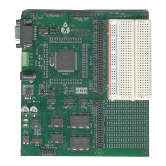
- Page 1 CML12S-DP256 Development Board for Motorola MC9S12DP256 ! Axiom Manufacturing • 2813 Industrial Lane • Garland, TX 75041 Email: Sales@axman.com Web: http://www.axman.com...
-
Page 2: Table Of Contents
C M L 1 2 S D P 2 5 6 0 1 / 3 0 / 0 4 CONTENTS GETTING STARTED ......................3 Installing the Software ....................4 Board Startup......................4 Support Software....................4 Software Development ...................5 TUTORIAL........................5 Creating Source Code ....................5 Assembling source code ..................6 Running your application ..................7 Programming HCS12 Flash EEprom ..............8... -
Page 3: Getting Started
0 1 / 3 0 / 0 4 GETTING STARTED The Axiom CML12S-DP256 single board computer is a fully assembled, fully functional development system for the Motorola MC9S12DP256 microcontroller. Provided with wall plug power supply and serial cable. Support software for this development board is provided for Windows 95/98/NT/2000/XP operating systems. -
Page 4: Installing The Software
0 1 / 3 0 / 0 4 Installing the Software 1. Insert the Axiom 68HC12 support CD in your PC. If the setup program does not start, run the file called "SETUP.EXE" on the disk. 2. Follow the instructions on screen to install the support software onto your PC. -
Page 5: Software Development
C M L 1 2 S D P 2 5 6 0 1 / 3 0 / 0 4 At minimum, you should install the AxIDE program. This provides the flash programming utility and communication with the board via the COM port and the supplied serial cable. This program includes a simple terminal for interfacing with other programs running on the CML12Sxxx and information from your own programs that send output to the serial port. -
Page 6: Assembling Source Code
CD and if you installed AxIDE, under that programs \EXAMPLE directory. You must use the example for the MCU type installed on the CML12Sxxx board. For example use the CML12S-DP256 example on the DP256 version board. You can assemble source code by using the AxIDE "BUILD" button or command line tools under a DOS prompt by typing: AS12 HELLO.ASM –L HELLO... -
Page 7: Running Your Application
C M L 1 2 S D P 2 5 6 0 1 / 3 0 / 0 4 If there are no fatal errors in your source code, 2 output files will be created: a Motorola S-Record file that can be loaded or programmed into HELLO.S19 memory a common listing file which provides physical address information... -
Page 8: Programming Hcs12 Flash Eeprom
C M L 1 2 S D P 2 5 6 0 1 / 3 0 / 0 4 You can modify the hello program to display other strings or do anything you want. The procedures for assembling your code, uploading it to the board and executing it remain the same. -
Page 9: Mon12 Operation
Start for application starting from Reset. MON12 operation notes: 1. CML12S-DP256 monitor application configures target HCS12 for 8MHz E clock, lower flash block (page $3E) disabled from memory map, and external access clock stretch set to 3 cycles. User can increase clock speed in application by modifying PLL control and setting new baud rate for serial port. -
Page 10: Mon12 Monitor Commands
C M L 1 2 S D P 2 5 6 0 1 / 3 0 / 0 4 B) Set Stack, Initialize memory map and SCI0 port and send prompt. C) Receive first character from Console port and execute monitor if ASCII text / command, else start utility mode for programming services. -
Page 11: Mon12 And Noice Memory Map
See the NOICE documentation for details. The CML12S-DP256 provides the NOICE debug monitor kernel as a subset of the MON12 monitor in reserved flash memory. User may apply the NOICE development system by setting the MON12 Autostart for the $F800 vector, reset the board and launch the NOICE host software on the PC. -
Page 12: Bdm Operation
2 hardware breakpoints. Operation Notes for BDM use: CML12S-DP256 MODC Option Jumper should be installed if a BDM is connected to the BDM Port. Default Mode is single-chip so the MODC option installed will force Special Single-chip Mode on Reset. -
Page 13: Options And Jumpers
C M L 1 2 S D P 2 5 6 0 1 / 3 0 / 0 4 2) After development by applying ram memory program pages $20 - $2D, user should relocate the paged program code to internal flash pages $30 - $3D for programming into the flash memory. -
Page 14: Auto Off / Spare
MODE The MODE option jumper is not installed on the CML12S-DP256 board and is hard connected by circuit copper trace for Single-chip Mode operation of the CPU. Both the MODA and MODB signals are terminated by this option. Due to the restriction that the HCS12 internal flash memory is the only nonvolatile program memory provided on the board, single Chip Mode is default. -
Page 15: Cut-Away Options 1 - 6
C M L 1 2 S D P 2 5 6 0 1 / 3 0 / 0 4 CUT-AWAY OPTIONS 1 - 6 CUT-AWAY options allow the user to disconnect dedicated HCS12 I/O port resources from development board peripherals. The CUT-AWAY options also allow for establishing the connection again by installing surface mount 1206 size 0 ohm resistors or mod wire with the use of a soldering iron. -
Page 16: Mcu_Port
C M L 1 2 S D P 2 5 6 0 1 / 3 0 / 0 4 MCU_PORT +5V 60 59 GND The MCU_PORT provides access to the peripheral PT7 58 57 PT6 features and I/O lines of the HCS12. PT5 56 55 PT4 PT3 54 53 PT2 ** Note signals with alternate connections on the... -
Page 17: Bus_Port
The KEYPAD / PORT H connector provides interface for the HCS12 port H or applying a keypad such as the Axiom Mfg. HC-KP. When applied as a KEYPAD connector, the interface is for a passive 4 x 4 matrix (16 key) keypad device. -
Page 18: Can Port
C M L 1 2 S D P 2 5 6 0 1 / 3 0 / 0 4 The 1,4,6,7,8, and 9 pins provide RS232 flow control and status. These are connected on the on the bottom of the development board to provide NULL status to the host. User may isolate pins and provide flow control or status connection to the host by applying HCS12 I/O signals and RS232 level conversion. -
Page 19: P1 - P4 Hcs12 Header Ring
TN (Standard Twist) style and Reflective to support this VEE potential. The Axiom Mfg. HC-LCD is also compatible. The LCD Module is configured in a Write only mode, it is not possible to read current cursor position or the busy status back from the module. -
Page 20: Bdm Port
C M L 1 2 S D P 2 5 6 0 1 / 3 0 / 0 4 1) The LCD write requires 3 SPI transfers. Transfer 1 provides data 0 - 3 and RS (register select) value. Transfer 2 provides the same data with the EN (D7) bit set. Transfer 3 provides same data with the EN bit clear. -
Page 21: Troubleshooting
C M L 1 2 S D P 2 5 6 0 1 / 3 0 / 0 4 TROUBLESHOOTING The CML12SXXX board is fully tested and operational before shipping. If it fails to function properly, inspect the board for obvious physical damage first. Ensure that all IC devices in sockets are properly seated. - Page 22 C M L 1 2 S D P 2 5 6 0 1 / 3 0 / 0 4 Tips and Suggestions Following are a number of tips, suggestions, and answers to common questions that will solve many problem users have with the CML12SXXX development system. You can download the latest software from the Support section of our web page at: www.axman.com Utilities...
- Page 23 C M L 1 2 S D P 2 5 6 0 1 / 3 0 / 0 4 TABLE 1: LCD Command and Character Codes Command codes are used for LCD setup and control of character and cursor position. All command codes are written to LCD panel address $B5F0.
- Page 24 C M L 1 2 S D P 2 5 6 0 1 / 3 0 / 0 4 TABLE 2: MON12 Service Routine Jump Table ADDRESS ff10 MAIN ; warm start ff13 BPCLR ; clear breakpoint table ff16 RPRINT ;...
- Page 25 C M L 1 2 S D P 2 5 6 0 1 / 3 0 / 0 4 TABLE 3: MON12 Interrupt Table MON12 Ram HCS12 Interrupt MON12 Vector Interrupt Vector Vector Address TRAP code Source 3F8C FF8C PWME 3F8E FF8E PTPI...
Need help?
Do you have a question about the CML12S-DP256 and is the answer not in the manual?
Questions and answers