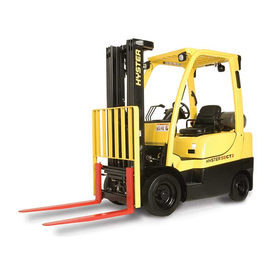
Summary of Contents for Hyster S50CT2
- Page 1 ELECTRICAL SYSTEM S50CT, S50CT2 [B267];H2.0-2.5CT (H50CT) [B274] PART NO. 4120745 2200 SRM 1771...
- Page 2 The Service Manuals are updated on a regular basis, but may not reflect recent design changes to the ® product. Updated technical service information may be available from your local authorized Hyster dealer. Service Manuals provide general guidelines for maintenance and service and are intended for use by trained and experienced technicians.
-
Page 3: Table Of Contents
Full Suspension Seats ........................... 18 Remove ............................... 18 Install ................................. 18 Transmission Pressure Sensors (Transducers) ....................19 Remove ................................19 Install ................................19 Transmission Temperature Sensor ........................19 Remove ................................19 Install ................................20 Rear Horn Button Switch ..........................20 ©2018 HYSTER COMPANY... - Page 4 Remove ................................30 Install ................................30 LED Tail, Backup, and Brake Lights .......................30 Remove ................................30 Install ................................31 Reflectors ................................31 Remove ................................31 Install ................................31 This section is for the following models: (S50CT, S50CT2) [B267]; H2.0-2.5CT (H50CT) [B274]...
-
Page 5: General
2200 SRM 1771 General General The removal and replacement procedures for the Diesel Engine in this manual for procedure to following electrical components are covered in this remove ECM from lift truck. manual: Display Switch Cluster • Power Distribution Module (PDM) •... -
Page 6: Engine Control Module (Ecm), Yanmar Diesel Engine
Engine Control Module (ECM), Yanmar Diesel Engine 2200 SRM 1771 Engine Control Module (ECM), Yanmar Diesel Engine Disconnect ECM connector from ECM. See REMOVE Figure 2. NOTE: ECM for Yanmar engine is located on left- hand side of frame. Remove four capscrews and ECM from bracket. See Figure 2. -
Page 7: Display Switch Cluster
2200 SRM 1771 Display Switch Cluster Display Switch Cluster Remove upper steering column cover by pulling REMOVE up on upper steering column cover to release NOTE: The Display Switch Cluster is a non- the latches (one on either side), and pulling repairable part.


Need help?
Do you have a question about the S50CT2 and is the answer not in the manual?
Questions and answers