Table of Contents
Advertisement
Quick Links
SHANGHAI BAUDCOM COMMUNICATION DEVICE CO.,LTD
Model: BD-E1-SIP
Trunk Gateway User Manual V2.0
Shanghai Baudcom Communication Device Co., Ltd.
Address: 519A,Building A,Lian ming Road 389,Min hang District , Shang hai City,China
Telephone: +86 21 37709251
Email:
info@baudcom.com.cn
Website: https://www.e1-converter.com/
Advertisement
Table of Contents

Related Manuals for Baudcom BD-E1-SIP


Summary of Contents for Baudcom BD-E1-SIP
- Page 1 SHANGHAI BAUDCOM COMMUNICATION DEVICE CO.,LTD Model: BD-E1-SIP Trunk Gateway User Manual V2.0 Shanghai Baudcom Communication Device Co., Ltd. Address: 519A,Building A,Lian ming Road 389,Min hang District , Shang hai City,China Telephone: +86 21 37709251 Email: info@baudcom.com.cn Website: https://www.e1-converter.com/...
- Page 2 BD-E1-SIP Trunk Gateway User Manual Revision Records File Name Trunk Gateway User Manual Document Version Firmware Version 1/2.01.04.03 Date 17/04/2014 Revised by Technical Support Department...
-
Page 3: Table Of Contents
Content 1. PRODUCT INTRODUCTION ......................1 1.1 Overview ..........................1 1.2 Equipment Structure......................1 1.2.1 Rear View ......................... 1 1.2.2 Front View ........................ 2 1.2.3 RJ-48c Line sequence ....................2 1.3 Functions and Features ......................3 1.3.1 Protocol standard supported ..................3 1.3.2 System Function ....................... - Page 4 2.9.1 SIP Parameter ......................27 2.9.2 SIP Trunk ....................... 27 2.10 IP Group Config ...................... 28 2.10.1 IP Profile ......................28 2.11 Voice & Fax ........................29 2.12 Maintenance ........................31 2.12.1 Management Parameter ..................31 2.12.2 Data Restore ......................32 2.12.3 Data Restore ......................
-
Page 5: Product Introduction
• BD-E1-SIP-2E1: two ports E1/T1 trunk gateway • BD-E1-SIP-4E1: four ports E1/T1 trunk gateway Notes: BD-E1-SIP support ISDN PRI by default, need to apply new license to enable SS7/R2 if necessary. 1.2 Equipment Structure 1.2.1 Rear View Figure 1-2-1 BD-E1-SIP Rear View... -
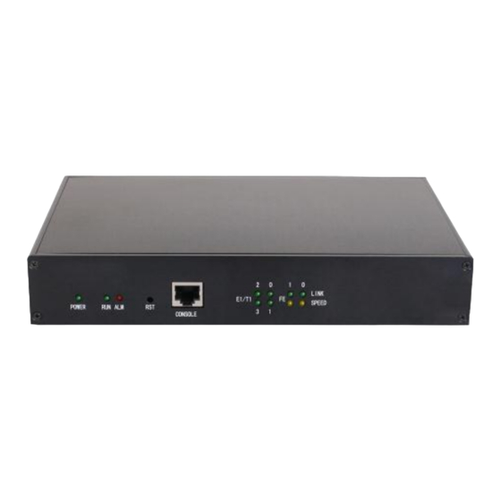
Page 6: Front View
192.168.1.111,default subnet mask is 255.255.255.0 Management Ethernet Interface. Default IP address is 192.168.11.1, default subnet mask is 255.255.255.0 1.2.2 Front View Figure 1-2-2 BD-E1-SIP Front View Table 1-2 -2 BD-E1-SIP Front View Description Function Color Work Status Off:Power is off... -
Page 7: Functions And Features
BD-E1-SIP trunk gateway adopts standard RJ-48C interface and impedance value is 120Ω. Connected end device by cross lines sequence. 1.3 Functions and Features 1.3.1 Protocol standard supported ● Standard SIP /PRI protocol ● Dynamic Host Configuration Protocol (DHCP) ● Point-to-Point Protocol over Ethernet (PPPoE) ●... -
Page 8: General Hardware Specification
● Acoustic noise: EN 300 753 ● CE EMC directive 2004/108/EC ● EN55022: 2006+A1:2007 ● EN61000-3-2: 2006, ● EN61000-3-3: 1995+A1: 2001+A2: 2005 ● EN55024: 1998+A1: 2001+A2: 2003 ● Certifications: FCC, CE 1.3.4 General hardware specification ● Power supply: 12VDC, 1A ●... -
Page 9: Parameter Setting
2. Parameter setting 2.1 Login First, device FE0 port connect PC with string, and then fill FE0 IP address in browser, FE0 default IP address is 192.168.1.111. It will request customer to input user name and password. Default user name and password are “admin”. If customer modified the default IP or forgot the IP, that can’t enter the configuration page. -
Page 10: Status &Statistics
Status &Statistics Users through to traverse the left navigation tree, and can complete view, edit and configuration device in the right configuration interface. TG configuration flow chart below:... -
Page 11: System Information
Time elapsed from device power on to now Traffic Statics Total bytes of message received and sent by FE0 port Equipment Type Equipment type; this equipment is: BD-E1-SIP Hardware Version Hardware version of device DSP Version Digital signal processing chip driver version... - Page 12 Table 2-2-2 Description of E1/T1 status 1. LOS Alarm: Signal loss alarm, this alarm is created when receiving is lost; please check the physical connection whether disconnected. 2. RAI Alarm: Receive remote alarm indication, it is a signal transmitted in the outgoing direction when a terminal determines that it has lost the incoming signal.
-
Page 13: Pstn Trunk Status
2.2.3 PSTN Trunk Status Figure 2-2-3 PSTN Trunk Status Table 2-2-3 Description of PSTN Trunk Status PRI Trunk No The number of PRI trunk, each trunk corresponds to a PRI link Trunk Name Used to identify the name of the trunk E1/T1Port No Indicate the E1/T1 line occupied by the PRI trunk. -
Page 14: Sip Call Statistics
Table 2-2-5 PRI Description of PRI call statistics PRI Trunk No The number of PRI trunk Trunk Name The name used to describe the PRI trunk Current Calls Number of lines that are being called currently Accumulated Calls Total number of calls from running start of system to current time. The percent of calls completed in total calls. -
Page 15: Network
2.3 Network Figure 2-3-1 Network Configuration Table 2-3-1 Description of Network Configuration Obtain IP address If Selected, the TG will obtain IP address via DHCP automatically Service Use the following IP If Selected ,Set a static IP for Service Ethernet Interface .Need Ethernet address to fill the IP address, Subnet Mask, and Default Gateway... -
Page 16: Pri Config
2.4 PRI Config 2.4.1 PRI Parameter Figure 2-4-1 PRI Parameter Table 2-4-1 Description of PRI Parameter Provide six plans: Unknown, ISDN/Telephony numbering plan, data numbering plan, telegraph numbering plan, national standard numbering Calling Party Numbering Plan plan, private numbering plan. The default is ISDN/Telephony numbering plan. -
Page 17: Pri Trunk
2.4.2 PRI Trunk Figure 2-4-2 PRI Trunk Click “Add” to add a PRI Trunk. If user want to delete or modify a PRI Trunk, please select the PRI Trunk user want to do. Figure 2-4-3 PRI Trunk Add Table 2-4-2 Description of Add PRI Trunk The number of PRI trunk;... -
Page 18: Ss7 Config (Optional)
Alerting Indication The ring signal include Alerting and Progress 2.6 SS7 Config (optional) SS7 configuration includes: SS7trunk, SS7 MTP Link, SS7 CIC and SS7 CIC Maintain. Figure 2-6-1 Add PRI Trunk 2.6.1 SS7 Trunk Figure 2-6-2 SS7 Trunk Figure 2-6-3 SS7 Trunk Add... - Page 19 SS7 is a standard protocol to initiate a calling connection with SPC exchange. Notes: 1. “Trunk No.” is a shared data, therefore, SS7 „Trunk No.‟ can't be the same as PRI “Trunk No.” 2. SPC length is 24bits when option “ANSI” or “ITU-CHINA” is selected in item “Standard Type”.
-
Page 20: Ss7 Mtp Link
2. If protocol standard chose'ITU', and then the SPC length is 14 bits. 3. SPC length performance on the OPC/DPC structure; SPC pattern instructions of the different structure OPC/DPC input formats. 4. When the SPC length is 24 bits, and chosen ITU, OPC/DPC structure format is :x-y-z; x、 y、 z is a number of 0-255, such as: 22-222-77 5. -
Page 21: Ss7 Circuit
SS7 MTP link description It is consistent with foregoing “Trunk No” of SS7 trunk. Trunk No Equipment maximum support 2 signaling links, these two links share workload, when one Link No link fails, the other link will take over the load until restore from failure, and then they will share the load again. -
Page 22: Ss7 Circuit Maintain
Start Channel The start of SS7 channel trunk Start CIC No An initial circuit number to this E1/T1 matches by both parties Count A total of 32 channels 2.6.4 SS7 Circuit Maintain According to the different operating modes, 7 circuit maintenance objects into two categories: ports and channel. - Page 23 Figure 2-6-8 SS7 Circuit Maintain-Channel If user wants to manage the channel, please select operation mode to channel. Select current port, use will see port status and protocol type. The following will show the slot and channel status. There are 16 kinds of channel states and each state corresponds to a color...
-
Page 24: R2 Config(Optional)
2.7 R2 Config(optional) 2.7.1 R2 Param Figure 2-7-1 R2 Parameter It is the default configuration for BD-E1-SIP. Description says the state name, means the different countries supported R2 parameters standards. According to demands add R2 parameters of user countries. - Page 25 Figure 2-7-2 R2 Parameter Add...
-
Page 26: R2 Trunk
Parameter Description Param ID Identification parameter group Description Description parameter information, Points out which countries standard the parameters are. CDbits C, Dbit value of A, B, C,Dbit in R2 lines of signaling. Request Next The rear party notices the front party ahead called number has received, and each other can DNIS send a next number. -
Page 27: Pstn Group Config
2.8 PSTN Group Config 2.8.1 E1/T1 Parameter Figure 2-8-1 E1/T1 Parameter Modify the E1/T1 parameters: Figure 2-8-2 E1/T1 Parameter Table 2-8-1 Description of Modify E1/T1 Parameter Work Mode E1 or T1, the default is E1 PCM Mode PCM mode: A LAW and Mu LAW, the default is A LAW Frame Mode The frame modes of E1/T1 are: DF, CRC-4, CRC4_ITU, the default is CRC-4;... -
Page 28: Dial Plan
Table 2-8-2 Description of Coder Group ID standard for Voice ability, total with 8 groups, where 0 is the default group ID Coder Group ID number, the codec that equipment supports in the grouping will be displayed in 0 group. Default value cannot be modified. Coder Support 3 kinds of voice codec: G.711A/U/G.729/G.723 Payload Type Value... -
Page 29: Dial Timeout
2. Maximum length is 30, this value is the number of the total length and including the prefix length. Click “Add” to add dial plan, configuration page as follow: Table 2-8-3 Description of Dial Plan The number to identify a dial plan Dial Plan ID Dial plan priority rules take effect in accordance with dial plan index size, and not Index... -
Page 30: Pstn Profile
Time to Reach Min Length(after Prefix) After receiving prefix number, the number has not yet reached the length of the minimum receiving number, the length of timeout Time to Reach Max Length(after Min Length) After receiving number, the number has reached the minimum length, but not reached the maximum length of the dial timeout 2.8.5 PSTN Profile... -
Page 31: Sip Config
2.9 SIP Config 2.9.1 SIP Parameter Figure 2-9-1 SIP Parameter SIP port number and domain name would be allowed to set to different ports and domain name. 2.9.2 SIP Trunk Figure 2-9-2 SIP Trunk Figure 2-9-3 SIP Trunk Add... -
Page 32: Ip Group Config
Table 2-9-1 Description of Add SIP Trunk Trunk No The range of trunk number is 0-1 Trunk Name Description the trunk Remote Address IP address of remote SIP platform i Remote Port Q.931 port of SIP of remote platform interfacing with this TG, the default is 5060 Local Domain Refer to SIP parameter... -
Page 33: Voice & Fax
Table 2-10-1 Description of Add IP Profile IP Profile ID The number to mart the IP Profile Description Description of the PSTN Profile Declare RFC2833 in SDP Support by default Support Early Media Whether support Early Media(183) Ringback Tone to PSTN IP->... - Page 34 Table 2-11-1 Description of Voice & Fax Disconnect Call when no RTP When selected “Yes”, detected call’s silence time packet longer than silence timeout that for a long time not received RTP packets, then hangup the call. Voice Parameter Period without RTP packet The maximum time length of silence PSTN in Gain Incoming PSNT gain...
-
Page 35: Maintenance
Fax Rx Gain Gain of receiving a fax Packet time Data packing duration Redundant frame in packet The length of frame in RTP packet Data Whether to allow the control of voice data Data & Fax Control Whether to allow the control of fax Continuous time The level of a frequency duration The time interval between two different... -
Page 36: Data Restore
Syslog Level None, Debug, Notice, Warning, Error. Please choose the file you want to output information level. Send CDR Whether send Call Detail Record through syslog Qos Type There are three options: none, TOS and DS. TOS only supports IPv4. NTP Enable Simple Network Management Protocol is enabled or not;... -
Page 37: Version Information
Table 2-12-3 Description of Data Restore Database Click "Browse" to select the Database file, and then click "Restore". Dialplan Click "Browse" to select the Dialplan file, and then click "Restore". 2.12.4 Version Information Figure 2-12-4 Version Information Here users can view software, database and web version information. 2.12.5 Firmware Upload Figure 2-12-5 Firmware Upload The process of firmware upload:... -
Page 38: Device Restart
The configuration items are used to change the login password of web configuration. 2.12.7 Device Restart Figure 2-9-7 Device Restart Some configuration need to restart device to take effect. Click “Restart” to restart the device. -
Page 39: Glossary
3. Glossary PRI: Primary rate interface FMC: Fixed Mobile Convergence SIP: Session Initiation Protocol DTMF: Dual Tone Multi Frequency PSTN:Public Switched Telephone Network STUN: Simple Traversal of UDP over NAT DMZ: Demilitarized Zone SS7: Signaling System No. 7 ISDN: Integrated Services for Digital Network SNMP: Simple Network Management Protocol DSCP: Differentiated Services Code Point OPC: Original Signaling Point Code...
Need help?
Do you have a question about the BD-E1-SIP and is the answer not in the manual?
Questions and answers