Advertisement
V2021.11.22
PRODUCT MANUAL
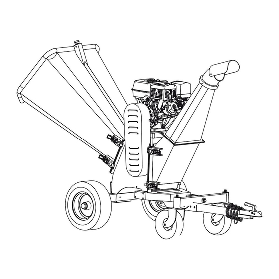
6" KOHLER® Powered Wood Chipper
14HP KOHLKER® Powered
MODEL: TMG-GWC6
Please read the product manual completely before assembly
Check against the parts list to make sure all parts are received
Wear proper safety goggles or other protective gears while in assembly
Missing parts or questions on assembly?
Please call: 1-877-761-2819 or email: cs@tmgindustrial.com
Do not return the product to dealer, they are not equipped to handle your
requests
WWW.TMGINDUSTRIAL.COM
Toll Free:1-877-761-2819
Advertisement

Related Manuals for TMG TMG-GWC6


Summary of Contents for TMG TMG-GWC6
- Page 1 PRODUCT MANUAL 6” KOHLER® Powered Wood Chipper 14HP KOHLKER® Powered MODEL: TMG-GWC6 Please read the product manual completely before assembly Check against the parts list to make sure all parts are received Wear proper safety goggles or other protective gears while in assembly Missing parts or questions on assembly? Please call: 1-877-761-2819 or email: cs@tmgindustrial.com...
-
Page 2: Table Of Contents
Table of Contents PART I: General Safety Rules.......................03 PART II: Familiar with the Wood Chipper....................09 PART III: Install the Wood Chipper...................10 PART IV: Operating the Wood Chipper.....................16 PART V: Maintaining the Wood Chipper....................18 PART VI: Troubleshooting and Parts List....................21 Conventions used in this manual WARNING This indicates a hazardous situation, which, if not avoided, could result in death or serious injury. -
Page 3: Part I: General Safety Rules
PART I: General Safety Rules Safety Labels Found on Your Unit W W W . T M G I N D U S T R I A L . C O M P 0 3 / 2 5 T o l l F r e e : 1 - 8 7 7 - 7 6 1 - 2 8 1 9... - Page 4 WARNING Read this Safety & Operating Instructions manual before you use the Wood Chipper. Become familiar with the operation and service recommendations to ensure the best performance of your machine. W W W . T M G I N D U S T R I A L . C O M P 0 4 / 2 5 T o l l F r e e : 1 - 8 7 7 - 7 6 1 - 2 8 1 9...
- Page 5 Propose CAUTION This machine is designed solely to chip wood and must not be used for any other purpose. It should only be used by trained operators who are familiar with the content of this manual. It is potentially hazardous to fit or use any parts other than your dealer parts. The company disclaims all liability for the consequences of such use, which in addition voids the machine warranty.
- Page 6 A. Keep in mind that the operator or user is responsible for accidents or hazards occurring to other people, their property, and themselves. B. Always wear protective goggles or safety glasses with side shields while using the Wood Chipper to protect your eyes from possible thrown debris. C.
- Page 7 heater, clothes dryer or furnace. G. Never make adjustments or repairs with the engine running. Shut down the engine, disconnect the spark plug wire, keeping it away from the spark plug to prevent accidental starting, wait 5 minutes before making adjustments or repairs. H.
- Page 8 M. Never operate the machine when under the influence of alcohol, drugs, or medication. N. Use the machine only in daylight. O. Stay alert for hidden hazards or traffic. Keep all nuts and bolts tight and keep the equipment in good operating condition. A Note to All Users List of warnings and cautions cannot be all-inclusive.
-
Page 9: Part Ii: Familiar With The Wood Chipper
PART II: Familiar with the Wood Chipper It may be helpful to familiarize yourself with the controls and features of the Wood Chipper. If you have any question, please contact the dealers in your area. TECHNICAL SPECIFICATIONS Start Recoil Start Engine 14HP four strokes Power... -
Page 10: Part Iii: Install The Wood Chipper
PART III: Install the Wood Chipper 1. After unpacking, check the following components Description Quantity Description Quantity Front wheel frame fixation 115 Tow bar assembly Rotate frame 116 Front wheel frame 109 T-sleeve 117 Black wheel assembly 112 Wrench 118 In-feed assembly 113 Discharge assembly 119 Main-frame assembly *.From 109 to 119,all parts both are combination parts, the parts list not include these parts... - Page 11 2. Installation in-feed assembly Parts no. Description Specifications Quantity In-feed assembly Main-frame assembly 3. Installation shaft and tire mounting W W W . T M G I N D U S T R I A L . C O M P 1 1 / 2 5 T o l l F r e e : 1 - 8 7 7 - 7 6 1 - 2 8 1 9...
- Page 12 Parts no. Description Specifications Quantity Tire 4.8-8 Slot nut M24x1.5 Rear axle shaft Washer Ø45x3 Wheel bearing cover Washer Ø14 Spring washer Bolt M14x145 M14x2 Main-frame assembly 4. Installation front wheel rack assembly Parts no. Description Specifications Quantity Front wheel frame fixation Washer Ø10 Bolt...
- Page 13 5. Installation front wheel rotating frame and trailer rod Parts no. Description Specifications Quantity Front wheel frame fixation Rotate frame Washer Ø12 Spring washer M12 x 1.75 Bolt M12 x 90 Bolt M12 x 70 B pin Tow bar assembly 6.
- Page 14 7. Installation discharge chute W W W . T M G I N D U S T R I A L . C O M P 1 4 / 2 5 T o l l F r e e : 1 - 8 7 7 - 7 6 1 - 2 8 1 9...
- Page 15 Parts no. Description Specifications Quantity Washer Ø8 Spring washer M8 x 1.25 Bolt M8 x 25 Discharge chute assembly Main-frame assembly 8. Connect wire Butt the wire joint W W W . T M G I N D U S T R I A L . C O M P 1 5 / 2 5 T o l l F r e e : 1 - 8 7 7 - 7 6 1 - 2 8 1 9...
-
Page 16: Part Iv: Operating The Wood Chipper
PART IV: Operating the Wood Chipper It may be helpful to better familiarize yourself with the features of your Wood Chipper before beginning the steps outlined in this chapter. WARNING Read and understand all instructions, safety precautions, and/or warnings listed in “PART I: General Safety Rules”... - Page 17 Stopping Move the Throttle Lever to IDLE. Recoil Start: Turn the Ignition Switch to the OFF position. Electric Start: Turn the Key to the OFF position. Operator Zone Wood Chipping NOTICE Woods’ and branches’ diameter should be no bigger than 120mm. WARNING Do not place your hands into the chute when loading.
-
Page 18: Part V: Maintaining The Wood Chipper
PART V: Maintaining the Wood Chipper Regular maintenance is the way to ensure the best performance and long life of your machine. Please refer to this manual and the engine manufacturer's user manual for maintenance procedures. WARNING Before performing any maintenance procedure or inspection, stop the engine, wait five minutes to allow all parts to cool. - Page 19 Replace the blade NOTICE The blade is a bidirectional blade. If one side of the blade is worn, the blade can be used after changing the direction without immediate replacement. Turn the roller axle with wrench 1. Loosen the screws with T wrench when you see the blade 2.
- Page 20 Adjust the clearance between blade and lower blade First, loosen the return screw NO. 79, Loosen lower blade fixing screw 78, mover 38 when roller blade and lower blade the clearance is 1-3mm,lock bolt 78 then lock bolt 79 Adjust blade clearance 1~3mm then lock screw...
-
Page 21: Part Vi: Troubleshooting And Parts List
PART VI: Troubleshooting and Parts List Most problems are easy to fix. Consult the Troubleshooting Table below for common problems and their solutions. If you continue to experience problems, contact the dealers in your area. WARNING Before performing any maintenance procedure or inspection, stop the engine, wait five minutes to allow all parts to cool. - Page 22 Parts Diagrams 119 Main-frame assembly W W W . T M G I N D U S T R I A L . C O M P 2 2 / 2 5 T o l l F r e e : 1 - 8 7 7 - 7 6 1 - 2 8 1 9...
- Page 23 118 In-feed assembly 113 Discharge assembly W W W . T M G I N D U S T R I A L . C O M P 2 3 / 2 5 T o l l F r e e : 1 - 8 7 7 - 7 6 1 - 2 8 1 9...
- Page 24 PARTS LIST Ref.No. Description Ref.No. Description Main-frame Deflector Infeed damping rubber Deflector washer Infeed chute Tire 4.8-8 Discharge drum rubber Fore-wheel fixture Discharge bottom part Axle cover Buckle Tire 4.4-4 Engine fixation Bearing FC207 Front wheel frame Slot nut M24*1.5 Front wheel rotation frame Switch fixation Fore-wheel frame welder...
- Page 25 Ref.No. Description Ref.No. Description Roller pulley Bolt M10X90 Bolt big head M5*10 Spring washer 10 Lower blade Spring washer 10 Rubber plate Bolt M10x80 Rubber plate layering Bolt M10X65 Belt cover Nut M10*1.5 Belt inner cover Bolt M16X140 Tow hitch Washer Ø16 Washer Nut M16X2...
Need help?
Do you have a question about the TMG-GWC6 and is the answer not in the manual?
Questions and answers