Table of Contents
Advertisement
Quick Links
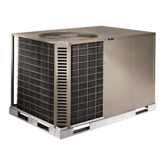
R-410A, 13 SEER
UB024-060
2-5 Ton
General . . . . . . . . . . . . . . . . . . . . . . . . . . . . . . . . . . . . . . . . . . 1
Installation . . . . . . . . . . . . . . . . . . . . . . . . . . . . . . . . . . . . . . . . 3
Limitations . . . . . . . . . . . . . . . . . . . . . . . . . . . . . . . . . . . . . . 3
Unit Location . . . . . . . . . . . . . . . . . . . . . . . . . . . . . . . . . . . . 4
Site Preparation . . . . . . . . . . . . . . . . . . . . . . . . . . . . . . . . . 4
Clearances . . . . . . . . . . . . . . . . . . . . . . . . . . . . . . . . . . . . . 5
(Manufactured Housing) . . . . . . . . . . . . . . . . . . . . . . . . . . . . . 7
Supply and Return Ducts . . . . . . . . . . . . . . . . . . . . . . . . . . 7
The Return - Air Grille Boxes . . . . . . . . . . . . . . . . . . . . . . 7
Wye Insulation. . . . . . . . . . . . . . . . . . . . . . . . . . . . . . . . . . . 8
Discharge Duct Installation . . . . . . . . . . . . . . . . . . . . . . . . . 9
Installing Of Duct To Unit (Residential) . . . . . . . . . . . . . . . . . 10
Installing Drain Tube And Connection . . . . . . . . . . . . . . . . . . 10
Service Access . . . . . . . . . . . . . . . . . . . . . . . . . . . . . . . . . . . 10
1 Unit Limitations . . . . . . . . . . . . . . . . . . . . . . . . . . . . . . . . . 4
2 Unit Dimensions . . . . . . . . . . . . . . . . . . . . . . . . . . . . . . . . 7
3 Unit Clearances . . . . . . . . . . . . . . . . . . . . . . . . . . . . . . . . . 8
4 Demand Defrost Selection . . . . . . . . . . . . . . . . . . . . . . . 15
5 Electrical Data . . . . . . . . . . . . . . . . . . . . . . . . . . . . . . . . . 16
6 Physical Data . . . . . . . . . . . . . . . . . . . . . . . . . . . . . . . . . 17
7 Airflow Performance . . . . . . . . . . . . . . . . . . . . . . . . . . . . 18
8 Additional Static Resistance . . . . . . . . . . . . . . . . . . . . . . 18
9 Electric Heat Minimum Supply Air . . . . . . . . . . . . . . . . . . 20
1 Component Location . . . . . . . . . . . . . . . . . . . . . . . . . . . . 4
2 Air Discharge Clearance . . . . . . . . . . . . . . . . . . . . . . . . . 5
3 Unit 4 Point Load Weight . . . . . . . . . . . . . . . . . . . . . . . . . 6
4 Unit Dimensions . . . . . . . . . . . . . . . . . . . . . . . . . . . . . . . . 7
5 Return Air Box and Grille . . . . . . . . . . . . . . . . . . . . . . . . . 8
6 Wye Installation (Outlet) . . . . . . . . . . . . . . . . . . . . . . . . . . 9
7 Wye Installation (Inlet and Outlet) . . . . . . . . . . . . . . . . . 10
General
UP Model UB units are factory assembled heat pump designed
to be installed along side the home or building. Field-installed
electric heater accessories are available to provide
supplemental electric heat.
The units are completely assembled on rigid base rails. All
piping, refrigerant charge, and electrical wiring is factory
installed and tested. The units require only electric power and
duct connections at the point of installation.
The electric heaters have nickel-chrome resistance wire
elements and utilize single point power connection.
TABLE OF CONTENTS
Compressors . . . . . . . . . . . . . . . . . . . . . . . . . . . . . . . . . . . 11
Power And Control Wiring . . . . . . . . . . . . . . . . . . . . . . . . . . . 11
Power Wiring . . . . . . . . . . . . . . . . . . . . . . . . . . . . . . . . . . . 11
Control Wiring . . . . . . . . . . . . . . . . . . . . . . . . . . . . . . . . . . 12
Wall Thermostat Installation . . . . . . . . . . . . . . . . . . . . . . . . . 12
Pre-start Procedure . . . . . . . . . . . . . . . . . . . . . . . . . . . . . . . . 13
System Startup, Check-out . . . . . . . . . . . . . . . . . . . . . . . . . . 13
Other Features Incorporated In The Control . . . . . . . . . . . . . 13
Anti-Short Cycle time Delay . . . . . . . . . . . . . . . . . . . . . . . 13
Safety Lock-Out . . . . . . . . . . . . . . . . . . . . . . . . . . . . . . . . 13
Airflow Performance . . . . . . . . . . . . . . . . . . . . . . . . . . . . . . . 17
Maintenance . . . . . . . . . . . . . . . . . . . . . . . . . . . . . . . . . . . . . 23
Normal Maintenance . . . . . . . . . . . . . . . . . . . . . . . . . . . . . 23
Typical Wiring Diagrams . . . . . . . . . . . . . . . . . . . . . . . . . . . . 24
LIST OF TABLES
10 Indoor Blower Specifications . . . . . . . . . . . . . . . . . . . . . . 20
11 Electric Heat Multipliers . . . . . . . . . . . . . . . . . . . . . . . . . . 20
12 UB024 Charging Table . . . . . . . . . . . . . . . . . . . . . . . . . . 21
13 UB030 Charging Table . . . . . . . . . . . . . . . . . . . . . . . . . . 21
14 UB036 Charging Table . . . . . . . . . . . . . . . . . . . . . . . . . . 22
15 UB042 Charging Table . . . . . . . . . . . . . . . . . . . . . . . . . . 22
16 UB048 Charging Table . . . . . . . . . . . . . . . . . . . . . . . . . . 23
UB060 Charging Table . . . . . . . . . . . . . . . . . . . . . . . . . . 23
17
LIST OF FIGURES
8 Duct Connector (With Damper) . . . . . . . . . . . . . . . . . . . 10
9 Duct Connector (No Damper) . . . . . . . . . . . . . . . . . . . . 10
10 Unit Component Location . . . . . . . . . . . . . . . . . . . . . . . . 13
11 Thermostat Wiring . . . . . . . . . . . . . . . . . . . . . . . . . . . . . 13
12 Switch Installation . . . . . . . . . . . . . . . . . . . . . . . . . . . . . 14
13
Defrost Operation Curves . . . . . . . . . . . . . . . . . . . . . . . 15
Safety Considerations
This is a safety alert symbol
labels or in manuals, be alert to the potential for personal injury.
Understand and pay particular attention the signal words
DANGER, WARNING or CAUTION.
DANGER indicates an imminently hazardous situation, which,
if not avoided, will result in death or serious injury.
WARNING indicates a potentially hazardous situation, which,
if not avoided, could result in death or serious injury.
CAUTION indicates a potentially hazardous situation, which, if
not avoided may result in minor or moderate injury. It is also
used to alert against unsafe practices and hazards involving
only property damage.
SO 9001
Certified Quality
Management System
. When you see this symbol on
876572-BIM-C-0213
Advertisement
Table of Contents

Related Manuals for York UB0 Series


Summary of Contents for York UB0 Series
-
Page 1: Table Of Contents
R-410A, 13 SEER UB024-060 2-5 Ton SO 9001 Certified Quality Management System TABLE OF CONTENTS General ......... . 1 Compressors . -
Page 2: General
876572-BIM-C-0213 Due to system pressure, moving parts, and electrical components, installation and servicing of air conditioning equipment can be hazardous. Only qualified, trained service personnel should install, repair, or service this equipment. Improper installation may create a condition where the Untrained personnel can perform basic maintenance functions operation of the product could cause personal injury or of cleaning coils and filters and replacing filters. - Page 3 876572-BIM-C-0213 Nomenclature U B 036 C 00 Product Style Product Category A = Style A U = Single Package Heat Pump, R-410A Product Generation Product Identifier 1 = First Generation B = 13 SEER Heat Pump 2 = Second Generation Nominal Cooling Capacity (MBH) Additional Options AA = None...
-
Page 4: Installation
876572-BIM-C-0213 Installation Refer to Table 6 for unit physical data and to Table 5 for electrical data. Limitations If components are to be added to a unit to meet local codes, These units must be installed in accordance with the following they are to be installed at the dealer's and/or the customer's national and local safety codes. -
Page 5: Unit Location
876572-BIM-C-0213 Unit Location heat pump base pan onto the ground below. A slight grade away from the unit will improve drainage. Several important factors must be considered before selecting 10. Average Winter Snow Depth - The heat pump must be the site for this unit: installed above the average snow depth to allow the Site –... -
Page 6: Clearances
876572-BIM-C-0213 Clearances All units require certain clearances for proper operation and service. Refer to Table 3 for the clearances required for construction, servicing and proper unit operation. Rear Left Right Front Figure 3: Unit 4 Point Load Weight Size Weight (lbs.) Center of Gravity 4 Point Load Location (lbs.) (Tons) -
Page 7: Unit 4 Point Load Weight
876572-BIM-C-0213 HIGH VOLTAGE CONN. Ø7/8" KNOCKOUT HIGH VOLTAGE CONN. Ø1 3/32" KNOCKOUT HIGH VOLTAGE CONN. Ø1 3/8" 15-13/16 KNOCKOUT 13-9/16 CONDENSATE DRAIN 3/4" NPT LOW VOLTAGE CONN. Ø7/8" BUSHING 7-7/16 4-13/16 4-3/8 DUCT FLANGE ØG 1-15/16 2-9/16 Unit Dimensions Figure 4: Table 2: Unit Dimensions Size Dimensions... -
Page 8: Installing Of Duct To Unit (Manufactured Housing)
876572-BIM-C-0213 Table 3: Unit Clearances Distance Distance Direction Direction (in.) (in.) Right Front Left Rear Bottom 1. Units must be installed outdoors. Over hanging structure or shrubs should not obscure condenser air discharge outlet. 2. Unit may be positioned to draw air from underneath structure. Installing Of Duct To Unit must be covered with a vapor barrier. -
Page 9: Wye Insulation
876572-BIM-C-0213 When attaching the flex duct to the return air box, secure Insert a stub collar in the raw end of the duct and tape the duct collar and return box collar together with at least securely in place. three (3) sheet metal screws and seal with duct tape. Make sure the duct is not stretched tight and does not have Set the return air box, with flex duct attached, back into the kinks from excessive length after installation. -
Page 10: Discharge Duct Installation
876572-BIM-C-0213 Grille Filter Return Box Damper* Flex Duct Grille 12” Duct Connectors Filter Return Box Damper* Flex Duct Flex Duct WYE Insulation Recommended 12 x12 x12 12 x12 x12 for Greater Efficiency and Performance of Unit. May use duct connector without damper if no interior furnace or air handler is connected to duct system. -
Page 11: Installing Of Duct To Unit (Residential)
876572-BIM-C-0213 If using the duct connector with damper, cut a 9-1/8”x 16-1/8” (located in the front corner of the unit), and the drain tube hole in the center of the duct bottom. If using the 12” diameter installed on the barbed end of the plastic fitting secured in duct connector without damper cut a 12-1/8”... -
Page 12: Compressors
876572-BIM-C-0213 Compressors Power And Control Wiring The compressor used in this product is specifically designed to Field wiring to the unit must conform to provisions of the current operate with R-410A Refrigerant and cannot be interchanged. N.E.C. ANSI/NFPA No. 70 or C.E.C. and/or local ordinances. The unit must be electrically grounded in accordance with local codes or, in their absence, with the N.E.C./C.E.C. -
Page 13: Control Wiring
876572-BIM-C-0213 Control Wiring Wall Thermostat Installation Run low voltage control circuit wires through the “fingered” snap bushing into the low voltage compartment. Run low voltage control circuit wires through the fingered snap bushing to the low voltage terminal wire. Refer to If installing this heat pump system in conjunction with a Figure 11 diagram to connect the low voltage control wiring gas furnace, a baffle must be installed in the furnace to... -
Page 14: Pre-Start Procedure
876572-BIM-C-0213 Raise the wall thermostat temperature selection lever to a Cooling Heating setting above the room temperature. The heat pump Thermostat Thermostat should now run in the heating mode. To check the emergency heat operation, set the wall thermostat system switch to EMERGENCY HEAT. Raise the wall thermostat temperature selection lever high enough to close the second stage of the thermostat, if it is not already closed. -
Page 15: Switch Installation
876572-BIM-C-0213 Defrost Operation inhibit feature prohibits defrost if the coil temperature is above 40°F. The demand defrost control implements a temperature differential (”delta-T”) demand defrost algorithm. The heat pump A forced-defrost feature puts the system into a defrost period is allowed to operate in the heating mode until the combination every 6 hours and 4 minutes to recirculate lubricants, unless the of outdoor ambient and outdoor coil temperatures indicate that coil temperature is above 40°F. -
Page 16: Demand Defrost Selection
876572-BIM-C-0213 Table 5: Electrical Data OD Fan Supply Factory Compressors Motors Blower Electric Heat Option Size MOCP Fuse (each) Volt (each) Motor (Tons) (Amps) (Amps) Size (Amps) Model Stages Amps None 22.1 2PH08520506 3.6/4.8 17.2/19.9 43.6/46.9 50/50 50/50 208/230-1-60 13.4 58.3 21.0 2PH08520706... -
Page 17: Electrical Data
876572-BIM-C-0213 Table 6: Physical Data Models Component UB024 UB030 UB036 UB042 UB048 UB060 Nominal Tonnage ARI COOLING PERFORMANCE Gross Capacity @ ARI A point (Btu) 23220 28750 37000 44000 47500 54384 ARI net capacity (Btu) 22600 28000 35200 42000 46000 53000 11.2 11.2... -
Page 18: Physical Data
876572-BIM-C-0213 Airflow Performance Table 7: Airflow Performance External Static Pressure (Inch Water Gauge) Size Unit Speed) (Tons) SCFM SCFM SCFM SCFM SCFM 1004 1115 Low/Medium 1005 1072 Medium 1037 1057 1121 (2.0) Medium/High 1185 1137 1071 1048 1010 1109 1170 High 1336 1031... -
Page 19: Airflow Performance
876572-BIM-C-0213 Table 8: Additional Static Resistance (Continued) Electric Heat, kW Size Model Wet Indoor Coil (Tons) 0.09 0.09 0.09 0.10 0.12 0.10 0.10 0.11 0.13 0.12 0.12 0.12 0.13 0.15 0.13 0.13 0.13 0.14 0.17 0.15 0.15 0.15 0.16 0.19 1000 0.17 0.17... - Page 20 876572-BIM-C-0213 Table 9: Electric Heat Minimum Supply Air Minimum Supply Air (CFM) Size Voltage Heater kW (Tons) 10.0 15.0 208/230-1-60 (2.0) 208/230-1-60 (2.5) 208/230-1-60 (3.0) 208/230-1-60 1300 1300 1270 1270 (3.5) 208/230-1-60 1300 1300 1270 1270 (4.0) 208/230-1-60 1300 1300 1270 1270 (5.0)
-
Page 21: Electric Heat Minimum Supply Air
876572-BIM-C-0213 Table 12: UB024 Charging Table Air Flow Outdoor Suction Suction Discharge Liquid Delta T Entering Leaving Compressor Indoor Db/Wb Pressure Temp. Pressure Temp. Evap Db Evap Db Amps 300 Cfm/Ton 80/62 300 Cfm/Ton 80/67 300 Cfm/Ton 80/72 300 Cfm/Ton 75/63 400 Cfm/Ton 80/62... -
Page 22: Ub024 Charging Table
876572-BIM-C-0213 Table 14: UB036 Charging Table Air Flow Outdoor Suction Suction Discharge Liquid Delta T Entering Leaving Compressor Indoor Db/Wb Pressure Temp. Pressure Temp. Evap Db Evap Db Amps 300 Cfm/Ton 80/62 300 Cfm/Ton 80/67 300 Cfm/Ton 80/72 300 Cfm/Ton 75/63 400 Cfm/Ton 80/62... -
Page 23: Ub036 Charging Table
876572-BIM-C-0213 Table 16: UB048 Charging Table Air Flow Outdoor Suction Suction Discharge Liquid Delta T Entering Leaving Compressor Indoor Db/Wb Pressure Temp. Pressure Temp. Evap Db Evap Db Amps 12.0 300 Cfm/Ton 13.8 80/62 15.9 12.2 300 Cfm/Ton 14.0 80/67 16.1 12.4 300 Cfm/Ton... -
Page 24: Maintenance
876572-BIM-C-0213 Maintenance MOTORS - Indoor and outdoor fan motors are permanently lubricated and require no maintenance. Normal Maintenance OUTDOOR COIL - Dirt should not be allowed to accumulate on the outdoor coil surface or other parts in the air circuit. Cleaning should be as often as necessary to keep the coil clean. -
Page 25: Typical Wiring Diagrams
876572-BIM-C-0213 Typical Wiring Diagrams UB024-060 Typical Heat Pump 208/230-1-60 volt Wiring Diagram Johnson Controls Unitary Products... - Page 26 876572-BIM-C-0213 UB036, 048 and 060 Typical Heat Pump 208/230-3-60 volt Wiring Diagram Johnson Controls Unitary Products...
- Page 27 876572-BIM-C-0213 UB060 Typical Heat Pump 460-3-60 volt Wiring Diagram Johnson Controls Unitary Products...
- Page 28 Subject to change without notice. Printed in U.S.A. 876572-BIM-C-0213 Copyright © 2013 by Johnson Controls, Inc. All rights reserved. Supersedes: 876572-BIM-B-1212 York International Corporation 5005 York Drive Norman, OK 73069...