Table of Contents
Advertisement
Quick Links
Advertisement
Chapters
Table of Contents

Subscribe to Our Youtube Channel
Related Manuals for Jetter JetViewMobile 104


Summary of Contents for Jetter JetViewMobile 104
- Page 1 User Manual JVM-104-O08 60884475_01 We automate your success.
- Page 2 Any revisions and technical advancements of our products are not automatically made available in a revised document. Jetter AG shall not be liable for any errors either in form or content, or for any missing updates, as well as for any damage or detriment resulting from such failure.
-
Page 3: Table Of Contents
Jetter AG Table of contents Table of contents Introduction ............................Information on this document ....................Typographical conventions ...................... Safety..............................General Information ......................... Purpose ........................... 2.2.1 Intended use ........................ 2.2.2 Usage other than intended ..................Warnings used in this document....................Product description ........................... - Page 4 Jetter AG Table of contents Identification and Configuration ......................21 Operating system........................21 7.1.1 Operating system update of the HMI................21 File system..........................24 7.2.1 Features ........................24 Programming ............................ 26 Abbreviations, module register properties and formats ............26 CANopen STX API ........................27 8.2.1...
-
Page 5: Introduction
For information on new revisions of this document, visit the download area on our website. This document is not subject to any updating service. Start | Jetter - We automate your success. For further information refer to the following information products: ■... -
Page 6: Safety
Jetter AG Safety | 2 2 Safety 2.1 General Information When placed on the market, this product corresponds to the current state of sci- ence and technology. In addition to the operating instructions, the laws, regulations and guidelines of the country of operation or the EU apply to the operation of the product. The op- erator is responsible for compliance with the relevant accident prevention regula- tions and generally accepted safety rules. -
Page 7: Warnings Used In This Document
Jetter AG Safety | 2 2.3 Warnings used in this document DANGER High risk Indicates an imminently hazardous situation which, if not avoided, will result in death or serious injury. WARNING Medium risk Indicates a potentially hazardous situation which, if not avoided, could result in death or serious injury. -
Page 8: Product Description
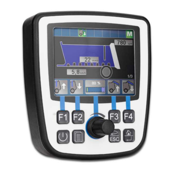
Jetter AG Product description | 3 3 Product description The JVM-104-O08 is a graphical HMI. Thanks to its compact design and in- tegrated controller, the HMI is versatile and has been specially developed for harsh applications in commercial vehicles and self-propelled machines. -
Page 9: Nameplate
Jetter AG Product description | 3 3.3 Nameplate Fig. 2: Nameplate Logo Serial number Barcode Article number and hardware revision Model code number 3.4 Scope of delivery Scope of delivery Item number Quantity JVM-104-O08 10001558 User Manual – JVM-104-O08... -
Page 10: Technical Data
Jetter AG Technical data | 4 4 Technical data This chapter contains electrical, mechanical data and operating data of the JVM-104-O08. 4.1 Dimensions 104.9 55.3 28.4 Fig. 3: Dimensions in mm 4.2 Mechanical specifications Parameter Description Standards Weight 350 g Vibration Broadband noise 10 Hz / 0.005 (m/s... -
Page 11: Electrical Properties
Jetter AG Technical data | 4 4.3 Electrical properties Power supply Parameter Description VBAT_ECU Nominal voltage DC 12 V or 24 V Maximum current 2 A Typical logic current con- 170 mA at DC 12 V sumption (VBAT_ECU) 90 mA at DC 24 V Power consumption Approx 2 W Integrated protective... -
Page 12: Environmental Conditions
Jetter AG Technical data | 4 The maximum permitted cable length depends on the baud rate being used and the number of CANopen devices being connected. Baud rate Max. cable length Max. stub length Total cable length 500 kBaud 100 m 5 m 30 m... -
Page 13: Emi Values
Jetter AG Technical data | 4 4.7 EMI values The JVM-104-O08 has E1 approval according to ECE R10 Rev. 5 and CE con- formity according to ISO 14982. Pulses ISO 7637-2 Test pulse Values Function class -450 V 2 a +37 V +20 V 3 a -150 V... -
Page 14: Mechanical Installation
Jetter AG Mechanical installation | 5 5 Mechanical installation NOTICE Damages to material or functional impairment due to welding Welding on the chassis may damage the device material, or impair device functions. ► Before you start welding, disconnect all connections be- tween the device and the electric system of the vehicle. -
Page 15: Requirements For The Installation Location
Jetter AG Mechanical installation | 5 5.1 Requirements for the installation location The installation location must meet the following requirements: ■ The installation location must allow air to circulate. ■ The installation location must be of sufficient size. ■ The device must be easily accessible to allow for service work. -
Page 16: Preparing For Installation
Jetter AG Mechanical installation | 5 5.2 Preparing for installation Mounting Use the following accessories for installation: accessories Accessories Item number Mounting plate for RAM Mount ball 10001621 consisting of mounting plate and screws for housing with Deutsch or M12 connector, without RAM Mount attach-... -
Page 17: Installing The Hmi
Jetter AG Mechanical installation | 5 5.3 Installing the HMI The illustration below shows how to install the device: Fig. 6: Installation drawing 2 x self-locking nuts 4 x screw for fixing to the JVM-104-O08 RAM Mount ball Mounting plate with opening for connector... -
Page 18: Fig. 7 Installing The Strain Relief
Jetter AG Mechanical installation | 5 Installing the strain Install strain reliefs for the connecting cables. relief ■ Ensure that there is sufficient clearance between the strain reliefs and the connectors. ■ Connectors must not be obstructed, so that they can be removed in the event of service. -
Page 19: Electrical Connection
Jetter AG Electrical connection | 6 6 Electrical connection NOTICE Damages to material or functional impairment Improper implementation of the wiring harness may cause mechanical stress. ► Protect the cables from bending, twisting or chafing. ► Install strain reliefs for the connecting cables. -
Page 20: Pin Assignment
Jetter AG Electrical connection | 6 6.1 Pin assignment 6.1.1 M12 male connector – voltage supply, CAN, ignition Function The M12 connector has the following function: ■ Power supply to the JVM-104-O08 ■ CANopen bus interface: CAN 1 ■ Recognition of the ignition signal... -
Page 21: Identification And Configuration
INFO Further information More information on this subject is available on our website. Start | Jetter - We automate your success. 7.1.1 Operating system update of the HMI This chapter describes how to update the operating system of a JVM-104-O08 HMI. -
Page 22: Tab. 14 Jeteasydownload Parameters
Identification and Configuration | 7 7.1.1.2 OS update via JetEasyDownload To update the operating system of this device, use a PEAK CAN dongle and the Jetter command line tool JetEasyDownload (version 1.00.0.15 or higher). JetEasyDownload To call JetEasyDownload you need specific parameters. Parameters... - Page 23 Jetter AG Identification and Configuration | 7 Carrying out the JetEasyDownload –H100 –T127 –B5 –S8000 –Ljvm_ce0_X.XX.X.XX.os update ü JetEasyDownload and PEAK CAN dongle are ready for use. ü There is a CAN connection between PEAK CAN dongle and JVM-104-O08. Call up JetEasyDownload with the above parameters and a valid OS file.
-
Page 24: File System
Jetter AG Identification and Configuration | 7 7.2 File system The file system allows for access to the files on the internal flash disk. Some files may be protected against read/write access or deletion. This is normal behavior. Some of these files are virtual files, such as firmware images, or protected files, such as EDS files. - Page 25 Jetter AG Identification and Configuration | 7 7.2.1.1 Flash disk - Properties Size The following disk space is available to the user: Parameter Value Flash disk capacity 512 MB Of which folder App 64 MB Of which folder Data 368 MB Features The internal flash disk drive has got the following properties: ■...
-
Page 26: Programming
Jetter AG Programming | 8 8 Programming 8.1 Abbreviations, module register properties and formats Abbreviations The abbreviations used in this document are listed in the table below: Abbreviation Description R 100 Register 100 MR 150 Module register 150 Tab. 15: Abbreviations Module register Each module register is characterized by certain properties. -
Page 27: Canopen Stx Api
Jetter AG Programming | 8 8.2 CANopen STX API The CANopen STX API is a platform allowing users to send and receive CANopen messages via STX functions. The device uses the STX functions to communicate with other CANopen nodes. The CANopen CANopen is an open standard for networking and communication, used e.g. -
Page 28: Canopen Object Directory
Jetter AG Programming | 8 Function Description The function CanOpenDownloadSDO() lets you ac- CanOpen cess a particular object in the Object Directory of the DownloadSDO() message recipient and specify the value of the ob- ject. Data is exchanged in accordance with the SDO download protocol. -
Page 29: Storage Options - Overview
Jetter AG Programming | 8 Index Object Object name Data type Access (hex) (Abbreviation) 1200 RECORD Server 1 – SDO parameter SDO parameter 1201 RECORD Server 2 – SDO parameter SDO parameter 1203 RECORD Server 3 – SDO parameter SDO parameter... -
Page 30: Application Program Memory
Jetter AG Programming | 8 8.3.3 Application program memory By default, the application program is uploaded from JetSym to the JVM-104-O08 and is stored there. Properties ■ Stored as file within the file system ■ Default directory \app\program name Type of access ■... -
Page 31: Storing Registers And Variables
Jetter AG Programming | 8 Properties of special ■ Global variables with dedicated addresses (%MX) flags ■ When the operating system is launched, special flags are initialized using their default values ■ Quantity: 256 ■ Flag numbers: 2048 ... 2303 Memory access ■... -
Page 32: Control Elements
Jetter AG Programming | 8 8.4 Control elements This chapter describes how to program the control elements of the JVM-104-O08. 8.4.1 Input keys The HMI JVM-104-O08 has the following 8 input keys: [F1], [F2], [F3], [F4], [POWER], [SCROLL], [ESC]and [HOME]. These input keys are user-program- mable. -
Page 33: Digipot
Jetter AG Programming | 8 Input key Value [ESC] 0x1B [HOME] 0x24 Tab. 21: Virtual key codes 8.4.2 Digipot The JVM-104-O08 has a rotary dial (digipot) with pushbutton feature which offers a convenient input option. The following provides details of the digipot's special registers with a corresponding sample program. -
Page 34: Ignition And Off Delay
Jetter AG Programming | 8 INFO Further information For more information on this subject, refer to the JetSym Online Help. 8.5 Ignition and OFF delay This chapter covers the ignition and the function Shutdown(). Special registers The special register 361100 of the JVM-104-O08 is responsible for prompting the state of the ignition. - Page 35 Jetter AG Programming | 8 Return value This function transmits the following return values to the higher-level program. Return value Description Ignition is still switched on INFO If the ignition is still switched on, the device will not be switched off. However, the HMI can be restarted. Such a...
-
Page 36: Saving And Loading An Application Program
Jetter AG Programming | 8 8.6 Saving and loading an application program The user determines the program that is to be executed. When uploading the ap- plication program to the controller, this program is stored as a file to the internal flash disk. -
Page 37: Registers - Overview
100708 Register Description range 100709 Month 100710 Year 361000 ... Bit-coded map of input keys 100711 TestNum. 361007 100712 TestRev. 100800 ... Features 100802 100800 Internal version number 100801 MAC address (Jetter) 100802 MAC address (JVM-104-O08) User Manual – JVM-104-O08... - Page 38 Jetter AG Registers - Overview | 9 Electronic nameplate (entire device) Register Description range Register Description range 107520 Size of the flash disk in bytes 107521 Used memory in bytes 100708 107522 Blocked memory in bytes 100709 Month 107523 Free memory in bytes...
- Page 39 Jetter AG Registers - Overview | 9 Application program Register Description Bit 13 Stack overflow Register Description Bit 14 Stack underflow 210000 Application program is running Bit 15 Illegal stack (bit 0 = 1) Bit 16 Error when loading the applica-...
- Page 40 Jetter AG Registers - Overview | 9 Register Description Register Description range 210074 Command for cyclic tasks 210075 Number of timers 361000.6 [ESC] 210076 Timer number (for R210077) 361000.7 [HOME] 210077 Timer value in milliseconds 361100 Ignition (IGN) 210100 ...
- Page 41 Jetter AG Registers - Overview | 9 Registers Description Registers Description 203114 96 ... 111 203146 2272 ... 2287 203115 112 ... 127 203147 2288 ... 2303 203116 128 ... 143 Application registers with overlaid 203117 144 ... 159 flags 203118 160 ...
- Page 42 Jetter AG Registers - Overview | 9 Registers Description Registers Description 1000034 1344 ... 1375 1000045 1696 ... 1727 1000035 1376 ... 1407 1000046 1728 ... 1759 1000036 1408 ... 1439 1000047 1760 ... 1791 1000037 1440 ... 1471 1000048 1792 ...
- Page 43 Jetter AG Registers - Overview | 9 System Functions For reasons of compatibility, the system functions are listed below. In JetSym STX, use the corresponding JetSym STX functions instead of the system functions. System function Description Converting BCD to HEX...
- Page 44 Jetter AG Registers - Overview | 9 System function Corresponding JetSym STX function Function Bcd2Hex(Bcd: int): Int; Function Hex2Bcd(Hex: int): Int; Function QSort(DataPtr: Int, ElementCnt: Int, ElementSize: Int, SortOffset: Int, SortType: STXBASETYPE, SortMode: QSORTMODE): Int; 90/91 Function FileDAWrite(Const Ref FileName: String, Const Ref Mode: String, VarType: DAWRITE_TYPE, First: Int, Last: int): Int;...
-
Page 45: Maintenance
Any liability for any damages resulting from the use of non-original parts and equipment is excluded. 10.2 Return and disposal How to dispose of Return your Jetter AG product to us for proper disposal. Visit our homepage waste equipment detailed information and to download the required Returns form. -
Page 46: Storage And Shipment
In case of damaged packaging inspect the device for any visible damage, and in- form your freight forwarder and the Jetter AG of the damage caused during ship- ment. If the device is damaged or has been dropped, it is strictly forbidden to use... -
Page 47: Service
To contact them, please call our technical hotline or use the contact form on our homepage: Technical hotline | Jetter - We automate your success. You are also welcome to send an e-mail to our technical hotline: hotline@jetter.de... -
Page 48: Spare Parts And Accessories
Only use accessories recommended by Jetter AG. 12.1 Accessories INFO Ordering accessories The accessories are not part of the scope of delivery. Suitable accessories can be obtained from Jetter AG. Accessories Item number Mounting plate for RAM Mount ball 10001621... - Page 49 Jetter AG List of figures List of figures Fig. 1 Design ............................Fig. 2 Nameplate ..........................Fig. 3 Dimensions in mm ........................10 Fig. 4 Space requirements for installation work (in mm) ..............15 Fig. 5 Screw holes, dimensions in mm ....................16 Fig.
- Page 50 Jetter AG List of tables List of tables Tab. 1 Mechanical specifications....................Tab. 2 Power supply VBAT_ECU ....................Tab. 3 CAN interface specification ....................Tab. 4 Specification - CAN bus cable ..................Tab. 5 Cable lengths........................Tab. 6 Environmental conditions ....................
- Page 51 Jetter AG Graeterstrasse 2 71642 Ludwigsburg www.jetter.de E-mail info@jetter.de Phone +49 7141 2550-0 We automate your success.
Need help?
Do you have a question about the JetViewMobile 104 and is the answer not in the manual?
Questions and answers