Table of Contents
Advertisement
Quick Links
Advertisement
Chapters
Table of Contents

Subscribe to Our Youtube Channel
Related Manuals for Jetter JetViewMobile 104


Summary of Contents for Jetter JetViewMobile 104
- Page 1 User Manual JVM-104-O13 60885470_00 We automate your success.
- Page 2 Any revisions and technical advancements of our products are not automatically made available in a revised document. Jetter AG shall not be liable for any errors either in form or content, or for any missing updates, as well as for any damage or detriment resulting from such failure.
-
Page 3: Table Of Contents
Jetter AG Table of contents Table of contents Introduction ............................Information on this document ....................Typographical conventions ...................... Safety..............................General Information ......................... Purpose ........................... 2.2.1 Intended use ........................ 2.2.2 Usage other than intended ..................Warnings used in this document....................Product description ........................... 10 Design............................ - Page 4 Jetter AG Table of contents Identification and Configuration ......................27 Operating system........................27 7.1.1 Operating system update of the HMI................27 File system..........................30 7.2.1 Features ........................31 User Manual – JVM-104-O13...
- Page 5 Jetter AG Table of contents Programming ............................ 32 Abbreviations, module register properties and formats ............32 CANopen STX API ........................33 8.2.1 STX Functions ......................33 8.2.2 CANopen object directory.................... 34 Storage options - Overview ..................... 35 8.3.1 Operating system memory ..................35 8.3.2...
- Page 6 Jetter AG Table of contents 12 Service .............................. 68 12.1 Customer service........................68 13 Spare parts and accessories ......................69 13.1 Accessories ..........................69 User Manual – JVM-104-O13...
-
Page 7: Introduction
For information on new revisions of this document, visit the download area on our website. This document is not subject to any updating service. Start | Jetter - We automate your success. For further information refer to the following information products: ■... -
Page 8: Safety
Jetter AG Safety | 2 2 Safety 2.1 General Information When placed on the market, this product corresponds to the current state of sci- ence and technology. In addition to the operating instructions, the laws, regulations and guidelines of the country of operation or the EU apply to the operation of the product. The op- erator is responsible for compliance with the relevant accident prevention regula- tions and generally accepted safety rules. -
Page 9: Warnings Used In This Document
Jetter AG Safety | 2 2.3 Warnings used in this document DANGER High risk Indicates an imminently hazardous situation which, if not avoided, will result in death or serious injury. WARNING Medium risk Indicates a potentially hazardous situation which, if not avoided, could result in death or serious injury. -
Page 10: Product Description
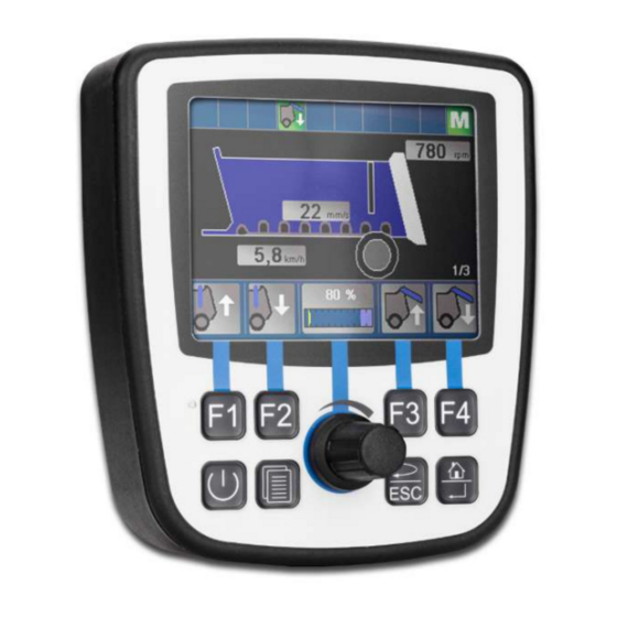
Jetter AG Product description | 3 3 Product description The JVM-104-O13 is a graphical HMI. Thanks to its compact design and in- tegrated controller, the HMI is versatile and has been specially developed for harsh applications in commercial vehicles and self-propelled machines. -
Page 11: Nameplate
Jetter AG Product description | 3 ■ 4 multi-purpose inputs/outputs, configurable: Digital active-low input, digital output up to 2.5 A, PWM output, H-bridge ■ Front/rear degree of protection: IP65/IP65 3.3 Nameplate Fig. 2: Nameplate Logo Serial number Barcode Article number and hardware revision Model code number 3.4 Scope of delivery... -
Page 12: Technical Data
Jetter AG Technical data | 4 4 Technical data This chapter contains electrical, mechanical data and operating data of the JVM-104-O13. 4.1 Dimensions 66.8 24.5 17.6 27.9 Fig. 3: Dimensions in mm 4.2 Mechanical specifications Parameter Description Standards Weight 350 g Vibration Broadband noise 10 Hz / 0.005 (m/s... -
Page 13: Electrical Properties
Jetter AG Technical data | 4 4.3 Electrical properties Power supply Parameter Description VBAT_ECU Nominal voltage DC 12 V or 24 V Maximum current 2 A Typical logic current con- 170 mA at DC 12 V sumption (VBAT_ECU) 90 mA at DC 24 V Power consumption Approx 2 W Integrated protective... -
Page 14: Multi-Purpose Inputs/Outputs
Jetter AG Technical data | 4 4.3.2 Multi-purpose inputs/outputs Power supply Parameter Description VBAT_PA Nominal voltage DC 12 V or DC 24 V Permissible voltage DC 8 V ... DC 32 V range VBAT_PA Maximum current 10 A Integrated protective Protection against polarity reversal functions Tab. 6: Technical data - Power supply VBAT_PA... -
Page 15: Tab. 10 Technical Data - Frequency Measurement
Jetter AG Technical data | 4 Frequency Parameter Description measuring Measuring range 0.1 Hz ... 10 kHz Accuracy 99.9 % Input resistance 20 kΩ Typical input current Max. 1 mA Maximum input fre- Max. 10 kHz quency Period measurement 1 μs resolution Adjustable gate times for 1 ms ... 10 s gate time measuring Duty cycle frequency in- 35 μs min. -
Page 16: Tab. 13 Technical Data - Digital Output
Jetter AG Technical data | 4 Digital output Parameter Description Maximum output current 2.5 A per channel Nominal voltage Supply voltage VBAT_PA Diagnostics Overcurrent, short circuit, cable break Overcurrent evaluation Adjustable current trip Maximum latency: 500 ms Switching between output and input Maximum total current The total current of all outputs must not exceed 8 A,... -
Page 17: Environmental Conditions
Jetter AG Technical data | 4 4.4 Environmental conditions Parameter Description Standards Operating temperature -20 °C ... +65 °C ISO 16750-4 Climatic conditions Humid heat Storage temperature -20 °C ... +70 °C ISO 16750-4 DIN EN 60068-2-1 DIN EN 60068-2-2 Relative humidity 10 % … 95 % DIN EN 61131-2 Pollution degree DIN EN 61131-2 Tab. 16: Environmental conditions 4.5 Display... -
Page 18: Emi Values
Jetter AG Technical data | 4 4.7 EMI values The JVM-104-O13 has E1 approval according to ECE R10 Rev. 5 and CE con- formity according to ISO 14982. Pulses ISO 7637-2 Test pulse Values Function class -450 V 2 a +37 V +20 V 3 a -150 V... -
Page 19: Mechanical Installation
Jetter AG Mechanical installation | 5 5 Mechanical installation NOTICE Damages to material or functional impairment due to welding Welding on the chassis may damage the device material, or impair device functions. ► Before you start welding, disconnect all connections be- tween the device and the electric system of the vehicle. -
Page 20: Requirements For The Installation Location
Jetter AG Mechanical installation | 5 5.1 Requirements for the installation location The device can directly be fastened to the vehicle or to a mounting plate. The installation location must meet the following requirements: ■ The installation location must allow air to circulate. -
Page 21: Preparing For Installation
Jetter AG Mechanical installation | 5 5.2 Preparing for installation Mounting Use the following accessories for installation: accessories Accessories Item number Mounting kit for JVM-104-O13 in flush-mount housing 10001371 consisting of mounting bracket and fixing screws Mounting surface Prepare the mounting surface for the JVM-104-O13 as follows: ►... -
Page 22: Installing The Hmi
Jetter AG Mechanical installation | 5 5.3 Installing the HMI The illustration below shows how to install the device: Fig. 6: Installation drawing 4x nut M4, self-locking, galvanized Mounting bracket 4x bolts EJOT 40x11/M4x23, galvanized with self-tapping thread Front panel gasket Screw the 4 bolts with the self-tapping thread into the holes provided for mounting the JVM-104-O13. -
Page 23: Fig. 7 Mounted Hmi - Top View
Jetter AG Mechanical installation | 5 Mounted HMI – top The illustration shows the mounted HMI: view Fig. 7: Mounted HMI – top view Installing the strain Install strain reliefs for the connecting cables. relief ■ Ensure that there is sufficient clearance between the strain reliefs and the connectors. -
Page 24: Electrical Connection
Jetter AG Electrical connection | 6 6 Electrical connection NOTICE Damages to material or functional impairment Improper implementation of the wiring harness may cause mechanical stress. ► Protect the cables from bending, twisting or chafing. ► Install strain reliefs for the connecting cables. -
Page 25: Fig. 9 Deutsch Connector, 12 Pins
Jetter AG Electrical connection | 6 INFO Current consumption When the device is energized, the current consumption is temporarily higher. To ensure a reliable start-up of the device, provide at least 3 times the typical current required. Signal Reference potential (GND) -
Page 26: Wiring - Example
Jetter AG Electrical connection | 6 Mating parts Compatible mating parts for the 12-pin DEUTSCH connector are as follows: Parameter Description Manufacturer Deutsch Manufacturer item DT06-12S number – housing Manufacturer item W12S number – wedge lock Manufacturer item num- 0-462-201-16141 ber –... -
Page 27: Identification And Configuration
INFO Further information More information on this subject is available on our website. Start | Jetter - We automate your success. 7.1.1 Operating system update of the HMI This chapter describes how to update the operating system of a JVM-104-O13 HMI. -
Page 28: Tab. 23 Jeteasydownload Parameters
Identification and Configuration | 7 7.1.1.2 OS update via JetEasyDownload To update the operating system of this device, use a PEAK CAN dongle and the Jetter command line tool JetEasyDownload (version 1.00.0.15 or higher). JetEasyDownload To call JetEasyDownload you need specific parameters. Parameters... - Page 29 Jetter AG Identification and Configuration | 7 Carrying out the JetEasyDownload –H100 –T127 –B5 –S8000 –Ljvm_ce0_X.XX.X.XX.os update ü JetEasyDownload and PEAK CAN dongle are ready for use. ü There is a CAN connection between PEAK CAN dongle and JVM-104-O13. Call up JetEasyDownload with the above parameters and a valid OS file.
-
Page 30: File System
Jetter AG Identification and Configuration | 7 7.2 File system The file system allows for access to the files on the internal flash disk. Some files may be protected against read/write access or deletion. This is normal behavior. Some of these files are virtual files, such as firmware images, or protected files, such as EDS files. -
Page 31: Features
Jetter AG Identification and Configuration | 7 7.2.1 Features The following properties apply to the internal flash disk: ■ Open a maximum of 8 files at the same time. ■ Separate directory names with a slash "/" rather than a backslash "\". -
Page 32: Programming
Jetter AG Programming | 8 8 Programming 8.1 Abbreviations, module register properties and formats Abbreviations The abbreviations used in this document are listed in the table below: Abbreviation Description R 100 Register 100 MR 150 Module register 150 Tab. 24: Abbreviations Module register Each module register is characterized by certain properties. -
Page 33: Canopen Stx Api
Jetter AG Programming | 8 8.2 CANopen STX API The CANopen STX API is a platform allowing users to send and receive CANopen messages via STX functions. The device uses the STX functions to communicate with other CANopen nodes. The CANopen CANopen is an open standard for networking and communication, used e.g. -
Page 34: Canopen Object Directory
Jetter AG Programming | 8 Function Description The function CanOpenDownloadSDO() lets you ac- CanOpen cess a particular object in the Object Directory of the DownloadSDO() message recipient and specify the value of the ob- ject. Data is exchanged in accordance with the SDO download protocol. -
Page 35: Storage Options - Overview
Jetter AG Programming | 8 Index Object Object name Data type Access (hex) (Abbreviation) 1200 RECORD Server 1 – SDO parameter SDO parameter 1201 RECORD Server 2 – SDO parameter SDO parameter 1203 RECORD Server 3 – SDO parameter SDO parameter... -
Page 36: Application Program Memory
Jetter AG Programming | 8 8.3.3 Application program memory By default, the application program is uploaded from JetSym to the JVM-104-O13 and is stored there. Properties ■ Stored as file within the file system ■ Default directory \app\program name Type of access ■... -
Page 37: Storing Registers And Variables
Jetter AG Programming | 8 8.3.5 Storing registers and variables Storing to a non- Registers and variables of the application program can be globally stored to a volatile (remanent) non-volatile memory with dedicated registers. memory The register variables %VL are always 4 bytes in size. They are not initialized by the operating system. -
Page 38: Control Elements
Jetter AG Programming | 8 8.4 Control elements This chapter describes how to program the control elements of the JVM-104-O13. 8.4.1 Input keys The HMI JVM-104-O13 has the following 8 input keys: [F1], [F2], [F3], [F4], [POWER], [SCROLL], [ESC]and [HOME]. These input keys are user-program- mable. -
Page 39: Digipot
Jetter AG Programming | 8 Input key Value [ESC] 0x1B [HOME] 0x24 Tab. 30: Virtual key codes 8.4.2 Digipot The JVM-104-O13 has a rotary dial (digipot) with pushbutton feature which offers a convenient input option. The following provides details of the digipot's special registers with a corresponding sample program. -
Page 40: Ignition And Off Delay
Jetter AG Programming | 8 INFO Further information For more information on this subject, refer to the JetSym Online Help. 8.5 Ignition and OFF delay This chapter covers the ignition and the function Shutdown(). Special registers The special register 361100 of the JVM-104-O13 is responsible for prompting the state of the ignition. - Page 41 Jetter AG Programming | 8 Return value This function transmits the following return values to the higher-level program. Return value Description Ignition is still switched on INFO If the ignition is still switched on, the device will not be switched off. However, the HMI can be restarted. Such a...
-
Page 42: Multi-Purpose Inputs
Jetter AG Programming | 8 8.6 Multi-purpose inputs The special registers of the HMI have got the functions listed below: ■ Programming multi-purpose inputs ■ Programming multi-purpose outputs ■ Retrieving the hardware and software version for I/O functions Placeholder x Placeholder x is for clearer representation. -
Page 43: Status And Instructions
Jetter AG Programming | 8 8.6.1 Status and instructions R 6010x0000 Status register MFQEx R 6010x0000 shows the status of the multi-purpose input MFQEx. Property Description Type Status register Type of access Read Reset Command: Activate multi-purpose input x Meaning of the individual bits... -
Page 44: Analog Functions
Jetter AG Programming | 8 8.6.2 Analog functions The multi-purpose inputs of the JVM-104-O13 provide the following analog fea- tures: ■ Voltage measuring ■ Current measurement R 6010x0002 Analog value MFQEx The register value results from measuring the analog value at multi-purpose input... -
Page 45: Digital Functions
Jetter AG Programming | 8 8.6.3 Digital functions The multi-purpose inputs of the JVM-104-O13 provide the following digital fea- tures: ■ Digital input ■ Frequency measuring ■ Counting mode R 6010x0003 Frequency value of MFQEx Depending on the configuration, this register displays the frequency, the period or a count value of the multi-purpose input x. -
Page 46: Multi-Purpose Outputs
Jetter AG Programming | 8 Enabling The command register for the multi-purpose input MFQEx is bit-coded. By setting frequency/period several bits, you can issue several commands simultaneously. measuring or counter function You can activate frequency or period measuring or the counting function for multi-... -
Page 47: Status And Instructions
Jetter AG Programming | 8 Registers - Each of the multi-purpose outputs PA1 to PA4 has got the following registers: Overview Register Description 6010x0000 Status (bit-coded) 6010x0001 Command (bit-coded) 6010x0002 PWM pulse control factor (duty cycle) in steps of 0.1 %... -
Page 48: Analog Functions
Jetter AG Programming | 8 R 6010x0001 Command register PA1 … PA4 The command register lets you set various operating modes and configure the re- spective PAx output. Property Description Type Command register Meaning of the individual bits Bit 1 … 0... -
Page 49: Digital Functions
Jetter AG Programming | 8 Activating the digital The command register for the multi-purpose output PAx is bit-coded. By setting output and several bits, you issue several commands simultaneously. measuring the current Example Command 0x0004 activates the output as digital low-side output. - Page 50 Jetter AG Programming | 8 Set the PWM pulse control factor to 60 %: R 6010x0002 := 600; Set the PWM frequency to 300 Hz: R 6010x0006 := 300; Activate the PWM output PAx as low-side output, for example: R 6010x0001 := 0x0005;...
-
Page 51: Multi-Purpose Outputs Pa3 And Pa4 Functioning As H-Bridges
Jetter AG Programming | 8 8.7.4 Multi-purpose outputs PA3 and PA4 functioning as H-bridges The JVM-104-O13 lets you control multi-purpose outputs PA3 and PA4 as H-bridges. To control an output as H-bridge, the program must include the following steps: Clockwise rotation Activate the low-side output of PA3. -
Page 52: Runtime Registers
Jetter AG Programming | 8 8.8 Runtime registers The JVM-104-O13 has several registers which are incremented by the operating system at regular intervals. These registers can be used to easily carry out time measurements in the application program. Overview of registers... - Page 53 Jetter AG Programming | 8 R 201003 Application time base units for R 201002 This register contains the multiplier for runtime register R 201002. Property Description Values 1 ... 2,147,483,647 (* 10 ms) Value after reset 10 (--> 100 ms)
-
Page 54: Saving And Loading An Application Program
Jetter AG Programming | 8 8.9 Saving and loading an application program The user determines the program that is to be executed. When uploading the ap- plication program to the controller, this program is stored as a file to the internal flash disk. -
Page 55: Registers - Overview
100708 Register Description range 100709 Month 100710 Year 361000 ... Bit-coded map of input keys 100711 TestNum. 361007 100712 TestRev. 100800 ... Features 100802 100800 Internal version number 100801 MAC address (Jetter) 100802 MAC address (JVM-104-O13) User Manual – JVM-104-O13... - Page 56 Jetter AG Registers - Overview | 9 Electronic nameplate (entire device) Register Description range Register Description range 107520 Size of the flash disk in bytes 107521 Used memory in bytes 100708 107522 Blocked memory in bytes 100709 Month 107523 Free memory in bytes...
- Page 57 Jetter AG Registers - Overview | 9 Application program Register Description Bit 13 Stack overflow Register Description Bit 14 Stack underflow 210000 Application program is running Bit 15 Illegal stack (bit 0 = 1) Bit 16 Error when loading the applica-...
- Page 58 Jetter AG Registers - Overview | 9 Register Description Register Description range 210074 Command for cyclic tasks 210075 Number of timers 361000.6 [ESC] 210076 Timer number (for R210077) 361000.7 [HOME] 210077 Timer value in milliseconds 361100 Ignition (IGN) 210100 ...
- Page 59 Jetter AG Registers - Overview | 9 Registers Description Registers Description 203114 96 ... 111 203146 2272 ... 2287 203115 112 ... 127 203147 2288 ... 2303 203116 128 ... 143 Application registers with overlaid 203117 144 ... 159 flags 203118 160 ...
- Page 60 Jetter AG Registers - Overview | 9 Registers Description Registers Description 1000034 1344 ... 1375 1000045 1696 ... 1727 1000035 1376 ... 1407 1000046 1728 ... 1759 1000036 1408 ... 1439 1000047 1760 ... 1791 1000037 1440 ... 1471 1000048 1792 ...
- Page 61 Jetter AG Registers - Overview | 9 System Functions For reasons of compatibility, the system functions are listed below. In JetSym STX, use the corresponding JetSym STX functions instead of the system functions. System function Description Converting BCD to HEX...
- Page 62 Jetter AG Registers - Overview | 9 System function Corresponding JetSym STX function Function Bcd2Hex(Bcd: int): Int; Function Hex2Bcd(Hex: int): Int; Function QSort(DataPtr: Int, ElementCnt: Int, ElementSize: Int, SortOffset: Int, SortType: STXBASETYPE, SortMode: QSORTMODE): Int; 90/91 Function FileDAWrite(Const Ref FileName: String, Const Ref Mode: String, VarType: DAWRITE_TYPE, First: Int, Last: int): Int;...
-
Page 63: Register Overview - Multi-Purpose Inputs And Outputs
Jetter AG Register overview - Multi-purpose inputs and outputs | 10 10 Register overview - Register Description range Multi-purpose inputs 601020000 Status MFQE2 and outputs 601020001 Command MFQE2 601020002 Analog value in µA/mV The following tables provide a highly condensed... - Page 64 Jetter AG Register overview - Multi-purpose inputs and outputs | 10 Multi-purpose inputs MFQE1 ... Register Description MFQE2 range These register numbers use x as a placeholder. 601050000 Multi-purpose output PA3 The following rule applies: … ■ x = 1 for multi-purpose output 1...
- Page 65 Jetter AG Register overview - Multi-purpose inputs and outputs | 10 Multi-purpose outputs PA1 ... PA4 Register Description 11 = Output PAx as low-side These register numbers use x as a placeholder. output The following rule applies: Bit 15 0 = Activate output ■...
-
Page 66: Maintenance
Any liability for any damages resulting from the use of non-original parts and equipment is excluded. 11.2 Return and disposal How to dispose of Return your Jetter AG product to us for proper disposal. Visit our homepage waste equipment detailed information and to download the required Returns form. -
Page 67: Storage And Shipment
In case of damaged packaging inspect the device for any visible damage, and in- form your freight forwarder and the Jetter AG of the damage caused during ship- ment. If the device is damaged or has been dropped, it is strictly forbidden to use... - Page 68 To contact them, please call our technical hotline or use the contact form on our homepage: Technical hotline | Jetter - We automate your success. You are also welcome to send an e-mail to our technical hotline: hotline@jetter.de...
- Page 69 Only use accessories recommended by Jetter AG. 13.1 Accessories INFO Ordering accessories The accessories are not part of the scope of delivery. Suitable accessories can be obtained from Jetter AG. Accessories Item number Mounting kit for JVM-104-O13 in flush-mount housing 10001371...
- Page 70 Jetter AG List of figures List of figures Fig. 1 Design ............................10 Fig. 2 Nameplate ..........................11 Fig. 3 Dimensions in mm ........................12 Fig. 4 Space requirements for installation work (in mm) ..............20 Fig. 5 Mounting surface dimensions in mm ..................21 Fig.
- Page 71 Jetter AG List of tables List of tables Tab. 1 Mechanical specifications....................Tab. 2 Power supply VBAT_ECU ....................Tab. 3 CAN interface specification ....................Tab. 4 Specification - CAN bus cable ..................Tab. 5 Cable lengths........................Tab. 6 Technical data - Power supply VBAT_PA ................
- Page 72 Jetter AG List of tables Tab. 38 Gate time for frequency measuring at multi-purpose input MFQEx ......... Tab. 39 Description of the placeholder x ..................Tab. 40 Register overview - Multi-purpose inputs ................. Tab. 41 Status register of the multi-purpose outputs PA1 … PA4..........
- Page 73 Jetter AG Graeterstrasse 2 71642 Ludwigsburg www.jetter.de E-mail info@jetter.de Phone +49 7141 2550-0 We automate your success.
Need help?
Do you have a question about the JetViewMobile 104 and is the answer not in the manual?
Questions and answers