Table of Contents
Advertisement
Quick Links
Advertisement
Table of Contents

Related Manuals for KNF LABOPORT SC820G


Summary of Contents for KNF LABOPORT SC820G
- Page 1 KNF 339416-339418 06/22 SC820G / SC840G TRANSLATION OF ORIGINIAL OPERATING INSTRUCTION ENGLISH VACUUM SYSTEM Notice! Before operating the pump and accessories, read and observe the operat- ing and installation instructions as well as the safety information!
-
Page 2: Table Of Contents
Table of contents 1 Scope of delivery................... 4 2 About this document ................ 6 2.1 Using the operating instructions............ 6 2.2 Exclusion of liability............... 6 2.3 Applicable documents.............. 7 2.4 Symbols and markings.............. 7 2.5 List of abbreviations .............. 10 3 Safety .................... - Page 3 10.2 Operation without the vacuum controller ........ 72 11 Servicing ..................... 73 11.1 Servicing schedule.............. 74 11.2 Cleaning.................. 75 11.3 Replace diaphragm, valve plates/seals and O-rings.... 76 11.4 Change O-rings on the complete vacuum system (optional) .. 85 12 Spare parts and accessories............... 88 12.1 Spare parts .................
-
Page 4: Scope Of Delivery
Key for hose connector (WAF 14) § Power supply incl. plug insert (EU, US, UK, AU) § Power cable § Operating instructions § QuickStart Fig.1: Scope of delivery (SC820G illustrated as example) Translation of Originial Operating Instruction, KNF 339416-339418 06/22... - Page 5 2. If the packaging is damaged, inform the responsible for- warding agent so that a damage report can be prepared. For further information, read Chapter 7 Transport [} 38]. Translation of Originial Operating Instruction, KNF 339416-339418 06/22...
-
Page 6: About This Document
à In the event of uncertainties with regard to the content of the operating instructions, please contact the manufac- turer (contact data: see www.knf.com). Have the type and serial number of the vacuum system at hand when doing à Read the operating instructions before putting the vacuum system into operation. -
Page 7: Applicable Documents
§ 3D model Also to be observed are: § Local terms and conditions § Sales documents and agreement between KNF and cus- tomer. 2.4 Symbols and markings Warning notice A notice that warns you of danger is lo- cated here. - Page 8 An activity to be carried out is specified here (a step). 1. The first step of an activity to be carried out is specified here. Other sequentially numbered steps follow. This symbol indicates important information. Translation of Originial Operating Instruction, KNF 339416-339418 06/22...
- Page 9 Symbol for separate tracking of electrical and electronic devices. The use of this sym- bol means that this product must be dis- posed of with normal household waste. Tab.2: Explanation of pictograms Translation of Originial Operating Instruction, KNF 339416-339418 06/22...
-
Page 10: List Of Abbreviations
Fluoroethylene propylene Tab. Table Fig. Figure a/o. And/or e.g. For example Perm. Permissible et al. And the like opt. If necessary Max. Maximum Min. Minimum High-performance condenser Separator Vacuum controller Charging cradle Translation of Originial Operating Instruction, KNF 339416-339418 06/22... -
Page 11: Safety
Tab.3: Target group Who-does-what Lifecycle phase User Specialized per- matrix sonnel Transport Setup Preparing for com- missioning Commissioning Operation Servicing Troubleshooting Disposal Tab.4: Who-does-what matrix Translation of Originial Operating Instruction, KNF 339416-339418 06/22... -
Page 12: Responsibility Of The Operator
Do not expose any body parts to the vacuum. Ensure that no hazards arise from gas flowing when gas con- nections are open, from the effects of noise or from hot, corro- sive, dangerous and environmentally hazardous gases. Translation of Originial Operating Instruction, KNF 339416-339418 06/22... -
Page 13: Operating Conditions
Make sure that a dangerous situa- tion cannot arise as a result. When pumping hazardous media, follow the safety regula- tions that apply for working with these media. Translation of Originial Operating Instruction, KNF 339416-339418 06/22... -
Page 14: Use
Technical data [} 26]) is not exceeded. If applicable, consider external energy sources (e.g., radiation sources) which may heat the medium further. In case of doubt, contact KNF Customer Service. 3.6 Use 3.6.1 Proper use The vacuum systems are intended exclusively for delivering gases and vapors. -
Page 15: Directives And Standards
§ 2014/30/EU (EMC) § 2006/42/EC (MD) The part of the pump that comes into contact with the media complies with Directive 2014/34/EU (ATEX). § UK Regulation S.I. 2008/1597 Supply of Machinery (Safety) Translation of Originial Operating Instruction, KNF 339416-339418 06/22... -
Page 16: Customer Service And Repair
Only have repairs to the vacuum systems performed by quali- fied KNF personnel. Housings with electrically live components may only be opened by specialist personnel. Use only genuine spare parts from KNF when performing servicing work. 3.9 Disposal Environmental Store the vacuum system and all replacement parts in accor- protection dance with the environmental protection regulations. - Page 17 The end user is responsible for disposing of old devices in ac- cordance with national and international regulations. Alterna- tively, KNF will also accept returns of KNF products (old de- vices) for a fee (see Chapter 14 Returns [} 98]). Translation of Originial Operating Instruction, KNF 339416-339418 06/22...
-
Page 18: Explosion Protection
EN ISO 80079-36 and DIN EN ISO 80079-37 was carried out for the vacuum systems. The explosion protection designation can also be found at the following location: § Vacuum system type plate Translation of Originial Operating Instruction, KNF 339416-339418 06/22... -
Page 19: Information On The Ex-Designation
Explosion protection Vacuum system SC820G / SC840G 4.2 Information on the Ex-designation This KNF vacuum system is marked with the following device designation according to the latest explosion protection direc- tive. The designation is only valid for the transfer section (me- dia-contacting region) of the vacuum system: Fig.2: EX-designation of the vacuum system... -
Page 20: Explanations Of The Explosion Protection Designation
Device group II Device group II applies for devices that are used in other ar- eas that could be endangered by an explosive atmosphere. Translation of Originial Operating Instruction, KNF 339416-339418 06/22... - Page 21 Devices of this category are designed for uses in areas in which it is to be expected that an explosive atmosphere resulting from stirred-up dust occurs, though in all likelihood occurs only seldom and for a very short length of time. Tab.6: Translation of Originial Operating Instruction, KNF 339416-339418 06/22...
- Page 22 The device must not be set up in potentially explosive atmos- the device pheres. It is only suitable for the transfer of explosive atmos- phere corresponding to its designation (see type plate). Translation of Originial Operating Instruction, KNF 339416-339418 06/22...
- Page 23 An ignition hazard evaluation according to the standards DIN EN ISO 80079-36 and DIN EN ISO 80079-37 was carried out for the devices.The protective goals were reached by applying ignition protection type constructional safety "c". Translation of Originial Operating Instruction, KNF 339416-339418 06/22...
- Page 24 § Do not set up the device in potentially explosive atmos- pheres. It is only suitable for the transfer of explosive at- mosphere corresponding to its designation (see type plate). Translation of Originial Operating Instruction, KNF 339416-339418 06/22...
- Page 25 Set up the device in such a way that it cannot be dam- aged from the outside. § Set up the device in such a way that it is not exposed to UV radiation. Translation of Originial Operating Instruction, KNF 339416-339418 06/22...
-
Page 26: Technical Data
AS hose connection FEP/FPM HLK hose connection FEP/FPM/PP HLK hose connector PVDF Overpressure relief valve PTFE Pressure sensor Ceramic Sealing rings FPM, FFPM Vent valve FPM, FFPM Tab.11: Materials of media-contacting components Translation of Originial Operating Instruction, KNF 339416-339418 06/22... - Page 27 **liters in standard state (1013 hPa, 20 °C; based on ISO 8778 and ISO 21360-1/2) Pneumatic connections Parameter Value Inlet hose connection [mm] ID 8 / 9.5 (Hose connector) Outlet hose connection [mm] (hose connector) ID 8 / 9.5 Tab.13: Pneumatic connections Translation of Originial Operating Instruction, KNF 339416-339418 06/22...
- Page 28 Max. current consumption [A] 0,66 – 0,35 1,0 – 0,6 Max. permissible mains volt- ± 10% ± 10% age fluctuations Tab.14: Electrical data Weight Device type Unit Weight SC820G [kg] 12,4 SC840G [kg] 14,8 Tab.15: Weight Translation of Originial Operating Instruction, KNF 339416-339418 06/22...
- Page 29 Dimensions L x H x W [mm] SC820G 347 x 416 x 260 SC840G 366 x 416 x 274 § Device protection Overcurrent protection § Overtemperature protec- tion (drive) § Blocking protection (drive) Tab.16: Other parameters Translation of Originial Operating Instruction, KNF 339416-339418 06/22...
- Page 30 Spare parts [} 88] Battery operating time* - Up to 8 h, depending of frequency of inputs and data transmission Charging time* Approx. 1 Tab.17: *Value applies for the rechargeable batteries included as standard Translation of Originial Operating Instruction, KNF 339416-339418 06/22...
- Page 31 Technical data Vacuum system SC820G / SC840G Use only the original power adapter from KNF to charge the vacuum system vacuum controller. Several vacuum systems within the range of the wireless connection can be operated in parallel via the associated vacuum controller.
-
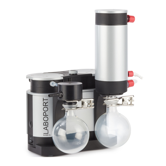
Page 32: Product Description And Function
5 Collection flask 6 Power switch 7 Signal cable 8 System inlet 9 Venting / Inert gas connec- tion Separator Status display Rotary/push knob Coolant con- nection Fig.3: Product description, vacuum system SC820G Translation of Originial Operating Instruction, KNF 339416-339418 06/22... - Page 33 A flask clamp (3) fixes the collection flask to the con- denser flange. A circulating cooler or running cold water (or other cooling medium) cools the high-performance condenser to condensation temperature. Translation of Originial Operating Instruction, KNF 339416-339418 06/22...
-
Page 34: Vacuum Controller
Product description and function Vacuum system SC820G / SC840G 6.2 Vacuum controller 1 Touchscreen 2 Charging cra- 3 Rotary/push knob 4 Charging socket 5 Charging con- tacts Fig.4: Vacuum controller Translation of Originial Operating Instruction, KNF 339416-339418 06/22... - Page 35 This takes place even when the vacuum controller is switched off. When the charge in the batteries is very low, the vacuum con- troller emits an acoustic signal. Translation of Originial Operating Instruction, KNF 339416-339418 06/22...
-
Page 36: Pump
(5) and the connecting rod (6). In the downwards stroke, it aspirates the gas to be transferred via the inlet valve (2). In the upwards stroke, the diaphragm presses the medium Translation of Originial Operating Instruction, KNF 339416-339418 06/22... -
Page 37: Gas Ballast
The final vacuum that can be achieved is not as deep when the gas ballast valve is open (see the chapter enti- tled 5 Technical data [} 26]). Translation of Originial Operating Instruction, KNF 339416-339418 06/22... -
Page 38: Transport
(e.g., safety shoes, safety gloves). à Transport the vacuum system in its original packaging to the installation site. à Keep the original packaging of the vacuum system (e.g. for later storage). Translation of Originial Operating Instruction, KNF 339416-339418 06/22... - Page 39 - 10 to + 60 Permissible humidity (non- 30 to 85 condensing) [%] Tab.18: Transport parameters Before commissioning, make sure that the vacuum system has reached the ambient temperature (5 Technical data [} 26]). NOTICE Translation of Originial Operating Instruction, KNF 339416-339418 06/22...
-
Page 40: Commissioning
à Protect the vacuum system from dust. à Protect the vacuum system from vibration, shock and ex- ternal damage. à Make sure that it is easy to operate the power switch. Translation of Originial Operating Instruction, KNF 339416-339418 06/22... - Page 41 If there are liquids in the collection flasks, empty them or dispose of the liquids in an environmentally friendly manner. à Store the collection flasks in a safe location. à Reassemble the collection flasks after transport. Translation of Originial Operating Instruction, KNF 339416-339418 06/22...
-
Page 42: Preparing For Commissioning
(separator) (see Chapter 8.4 Connecting the vacuum con- troller to the vacuum system [} 50]) Vacuum - Charging cradle connected to the power system adapter Tab.19: Operating requirements for commissioning Translation of Originial Operating Instruction, KNF 339416-339418 06/22... -
Page 43: Perform Commissioning
Ensure the proper use of the vacuum system (see Chap- ter Proper use). à Eliminate the possibility of improper use of the vacuum system (see Chapter 3.6.2 Foreseeable misuse [} 15]). à Observe the safety instructions (see Chapter 3 Safety [} 11]). Translation of Originial Operating Instruction, KNF 339416-339418 06/22... - Page 44 (see 5 Technical data [} 26]). In order for the high-performance condenser to recover solvent from the pumped gas, it must be cooled by means of a cold water connection or circulating cooler. Translation of Originial Operating Instruction, KNF 339416-339418 06/22...
- Page 45 (relieve pump pneumatically). Connecting the pump The following item numbers refer to Fig. 3. 1. Connect the signal cable to the pump (see Fig. 3/7) and the separator (Fig. 23/3) (see Fig. 7). Translation of Originial Operating Instruction, KNF 339416-339418 06/22...
- Page 46 Ensure that the signal cable is correctly aligned with the separator (30° angle; see Fig. 7). 2. Remove the protective caps from the pneumatic connec- tions of the vacuum system (see 1 and 8 or 1 and 7). Translation of Originial Operating Instruction, KNF 339416-339418 06/22...
- Page 47 6. Install the coolant supply and coolant drain on the con- denser (see 12). 7. Plug the plug of the power cable into a properly installed, grounded socket. Translation of Originial Operating Instruction, KNF 339416-339418 06/22...
-
Page 48: Switching The Vacuum Controller On And Off
To switch the vacuum controller off, press the rotary/push knob (Fig. 4/3) for about 2 seconds. A new view appears on the touchscreen. To switch off completely, press the key (Fig. 9/1). Translation of Originial Operating Instruction, KNF 339416-339418 06/22... - Page 49 Commissioning Vacuum system SC820G / SC840G 1 Switching the vacuum con- troller off 2 Canceling the switch-off pro- cedure Fig.9: Switching the vacuum controller off Translation of Originial Operating Instruction, KNF 339416-339418 06/22...
-
Page 50: Connecting The Vacuum Controller To The Vacuum System
When the vacuum controller is connected to the vacuum system with a cable, the mini-USB port cannot be used to connect a PC.To connect PC, the USB cable between the vacuum controller and the vacuum system must be removed. Translation of Originial Operating Instruction, KNF 339416-339418 06/22... - Page 51 (drive) is triggered and the vacuum system switches off. à Ensure that no pressure is present in the lines when switching on. à Switch on the vacuum system with the power switch (see Fig. 11). Translation of Originial Operating Instruction, KNF 339416-339418 06/22...
- Page 52 The vacuum system can be stopped immediately with the ro- tary/push knob (see Fig. 12). If the emergency stop is actu- ated, the light ring (10/6.1 SC820G, SC840G [} 32]) lights up continuous red. Translation of Originial Operating Instruction, KNF 339416-339418 06/22...
- Page 53 Switch off the vacuum system with the power switch (see 6/Fig. 3). à Establish normal atmospheric pressure in the lines (re- lieve pump pneumatically). à Pull mains plug of vacuum system out of socket. Translation of Originial Operating Instruction, KNF 339416-339418 06/22...
- Page 54 100% ON (continuous light) Emergency stop pressed 50% ON; 50% OFF Temperature too high (drive) 90% ON, 10% OFF Other fault Tab.20: Fault signal via status display For further information, see Chapter 13 Troubleshooting [} 91]. Translation of Originial Operating Instruction, KNF 339416-339418 06/22...
- Page 55 Vacuum system SC820G / SC840G 10 Operating the vacuum system 10.1 Vacuum controller 10.1.1 General functions and displays 1 Touchscreen 2 Charging cra- 3 Rotary/push knob 4 Charging socket 5 Charging con- tacts Fig.13: Vacuum controller Translation of Originial Operating Instruction, KNF 339416-339418 06/22...
- Page 56 Operating buttons (Fig. 15) with the functions: à Starting and stopping a process (4); à Opening and closing the venting valve (2); à Opening and closing the coolant valve (accessory) of the condenser (3). Translation of Originial Operating Instruction, KNF 339416-339418 06/22...
- Page 57 Check that the vacuum controller and the vacuum sys- tem are paired every time before using the handheld ter- minal. To do this, use the paging function (see "CALLING THE VACUUM SYSTEM"). Translation of Originial Operating Instruction, KNF 339416-339418 06/22...
- Page 58 5 Settings 6 Process time 7 Pump perfor- mance as a percentage or setpoint pres- sure in se- lected pres- sure unit (de- pending on the mode) Translation of Originial Operating Instruction, KNF 339416-339418 06/22...
- Page 59 Green = Start Red = Stop 5 Button for au- tomatic pres- sure reduction: Press = End (the current pressure is adopted as the setpoint pres- sure) Fig.15: Menus and buttons on the touchscreen Translation of Originial Operating Instruction, KNF 339416-339418 06/22...
-
Page 60: Operation
Menu language To select the menu language, go to Settings (Fig. 14/5). In Settings (Fig. 16), you can choose from the following menu languages: German, English, French, Italian, Spanish and Dutch (Fig. 17). Translation of Originial Operating Instruction, KNF 339416-339418 06/22... - Page 61 Torr or Hg (see Fig. 18). The pressure unit can be selected by going to Settings (Fig. 16) and selecting the Pressure unit menu there (Fig. 16/4). Translation of Originial Operating Instruction, KNF 339416-339418 06/22...
- Page 62 Fig.18: Pressure unit menu Modes The current mode is displayed on the touchscreen of the vac- uum controller .Pressing this row of the touchscreen opens the menu for changing the mode (see Fig. 19). Translation of Originial Operating Instruction, KNF 339416-339418 06/22...
- Page 63 Switch to manual process control (using rotary/push knob) à Brief press of the rotary/push knob: If the rotary knob is pressed briefly during an active process the process switches to "temporary pressure reg- ulation". Translation of Originial Operating Instruction, KNF 339416-339418 06/22...
-
Page 64: Operating The Vacuum System
When the venting valve is activated, the symbol is red and rotates (CCW). If the venting valve is permanently open (CLOSE but- ton appears in the display), it can be closed again by pressing the CLOSE (Fig. 15/2) button. Translation of Originial Operating Instruction, KNF 339416-339418 06/22... - Page 65 (see Fig. 20). Scre Start Au- en 1 tomatic mode Scre Detect en 2 boiling point; sub- sequent regulation to this pressure Scre Automatic en 3 pressure reduction Fig.20: Automatic function workflow Translation of Originial Operating Instruction, KNF 339416-339418 06/22...
- Page 66 For this, the individual "operating points" can be programmed in one after the other and then started.After starting, the pump works through the individual operating points in order and with the desired time intervals. Translation of Originial Operating Instruction, KNF 339416-339418 06/22...
- Page 67 3. Additional options (Column "+") for influencing the function process sequence: à CV1: Open coolant valve (accessory); à CV0: Close coolant valve (accessory) à S: Jump - The system is evacuated/vented to the desired pressure as quickly as possible. Translation of Originial Operating Instruction, KNF 339416-339418 06/22...
- Page 68 The following symbols can be rotated into view below the value 00:00:00 in the column for time intervals: à = Repetition. Repeats all operating points that were defined previously in the desired repetition se- quences. Translation of Originial Operating Instruction, KNF 339416-339418 06/22...
- Page 69 "No connection" symbol (see Fig. 22) appears in the display on the vacuum controller. To remedy this, see Chapter 13 Troubleshooting [} 91]. Translation of Originial Operating Instruction, KNF 339416-339418 06/22...
- Page 70 Introducing the vacuum controller to the pump (pairing) 1. Go to Settings on the vacuum controller (see Fig. 14/5). 2. Press the displayed MAC address of the connected Blue- tooth device (Fig. 16/6). Translation of Originial Operating Instruction, KNF 339416-339418 06/22...
-
Page 71: Vacuum Controller
Never use new batteries together with used batteries. All batteries must always be replaced at the same time. 7. Put the cover back on. 8. Dispose of old batteries in accordance with the regula- tions in force. Translation of Originial Operating Instruction, KNF 339416-339418 06/22... -
Page 72: Operation Without The Vacuum Controller
(accessory) of the condenser 5 Venting / Inert gas connec- tion 6 Inlet 7 Mini-USB - cable con- nection to handheld ter- minal - cable con- nection to PC Fig.23: Separator SC Translation of Originial Operating Instruction, KNF 339416-339418 06/22... -
Page 73: Servicing
à Servicing may only be performed according to the legal regulations (e.g. work safety, environmental protection) and provisions. à Servicing may only be performed by specialized personnel or trained and instructed personnel. Translation of Originial Operating Instruction, KNF 339416-339418 06/22... -
Page 74: Servicing Schedule
à Periodically check for no- ticeable changes to noises and vibrations. à Diaphragm and valve plates/ At the latest, replace seals when the performance de- creases. Tab.22: Servicing plan Translation of Originial Operating Instruction, KNF 339416-339418 06/22... -
Page 75: Cleaning
11.2.2 Clean vacuum system à Clean the vacuum system exterior only with a damp cloth and non-flammable cleaning agents. à If compressed air is available, blow out the parts. Translation of Originial Operating Instruction, KNF 339416-339418 06/22... - Page 76 As standard, only the elastomer parts of the pump are re- placed during servicing. For servicing of the complete vac- uum system, please refer to Chapter Change O-rings on the complete vacuum system (optional). Translation of Originial Operating Instruction, KNF 339416-339418 06/22...
- Page 77 If necessary, use a size 14 open-end wrench to loosen the union screw of the separator hose connection (1/Fig. 24). 1 Hose connec- tion Fig.24: Loosen hose connection Translation of Originial Operating Instruction, KNF 339416-339418 06/22...
- Page 78 The two internal head screws (1/Fig. 26) remain tight- ened for the time being. 1 Handle 2 Screw 3 Handle cover 4 Head screw 5 HLK hose connection Fig.25: Remove handle cover Translation of Originial Operating Instruction, KNF 339416-339418 06/22...
- Page 79 1. Mark the pressure plate (2), head plate (3) and intermedi- ate plate (6) with a continuous pencil stroke. This prevents the parts from being incorrectly mounted later on. 2. Remove the external screws (4/Fig. 25) of the pump heads. Translation of Originial Operating Instruction, KNF 339416-339418 06/22...
- Page 80 (8) are used in the same quantity as previously. 1. Press down one diaphragm (7) so that the other di- aphragm is in the upper change point. Translation of Originial Operating Instruction, KNF 339416-339418 06/22...
- Page 81 2. Pull the connection tube (10/Fig. 28) out of the head plate tube O-ring (3). The two hose connections (11) and (12) remain mounted in the head plates. 3. Replace the two O-rings (14) on the interconnection tube (10/Fig. 28). Translation of Originial Operating Instruction, KNF 339416-339418 06/22...
- Page 82 (5). 4. Place the pressure plate (2) on the head plate (3) accord- ing to the pencil line. 5. Perform steps 3 and 4 for the second pump head. Translation of Originial Operating Instruction, KNF 339416-339418 06/22...
- Page 83 9. Tighten the screws (4Fig. 25) in a crosswise pattern (tight- ening torque: SC820G: 4 Nm; SC840G: 5 Nm) 10. Screw in the union screw of the separator hose connec- tion (1/Fig. 24) on the separator adapter as far as it will go. Translation of Originial Operating Instruction, KNF 339416-339418 06/22...
- Page 84 4. Integrate the vacuum system into your application: à Connect the lines on the pneumatic inlet and outlet to the vacuum system. à Connect the vacuum system electrically. à Check the vacuum system for functionality. Translation of Originial Operating Instruction, KNF 339416-339418 06/22...
-
Page 85: Replace Diaphragm, Valve Plates/Seals And O-Rings
If necessary, use a size 14 open-end wrench to loosen the union screws. 11 AS hose connection 12 HLK hose connection 15 O-ring 16 O-ring 17 O-ring 18 O-ring 19 O-ring 20 AS hose connector Fig.30: Changing O-rings Translation of Originial Operating Instruction, KNF 339416-339418 06/22... - Page 86 3. Screw the hose connector (20) back into the separator adapter as far as it will go. 4. Loosen the flask clamp (3/Fig. 3) and remove the collec- tion flask (4/Fig. 3) from the separator adapter (10/Fig. 3). Translation of Originial Operating Instruction, KNF 339416-339418 06/22...
- Page 87 Servicing Vacuum system SC820G / SC840G 5. Change the O-ring (18) of the separator adapter. 6. Dispose of the replaced O-rings properly. Translation of Originial Operating Instruction, KNF 339416-339418 06/22...
-
Page 88: Spare Parts And Accessories
Vacuum system SC820G / SC840G 12 Spare parts and accessories To order spare parts and accessories, please contact your KNF sales partner or KNF Customer Service (con- tact data: see www.knf.com). 12.1 Spare parts Spare parts for standard servicing of the pump (see 11.3 Replace diaphragm, valve plates/seals and O-rings [} 76]) - Page 89 System SC820G* 338823 System SC840G* 338824 Tab.27: Spare parts set *includes in each case the spare parts set for the pump + additional O-rings for optional servicing of the complete vacuum system Translation of Originial Operating Instruction, KNF 339416-339418 06/22...
-
Page 90: Accessories
HLK hose connection 317157 Flask clamp 025968 Charging cradle incl. power 336784 adapter Battery set for vacuum con- 339004 troller (see 10.1.3 Changing the bat- teries in the vacuum controller [} 71]) Tab.28: Accessories Translation of Originial Operating Instruction, KNF 339416-339418 06/22... -
Page 91: Troubleshooting
No voltage in the elec- Check the room safety equipment and switch it on if trical mains. necessary. Tab.29: Troubleshooting: Vacuum system is switched on, but the power switch is not illuminated Translation of Originial Operating Instruction, KNF 339416-339418 06/22... - Page 92 Connect the gas ballast. à Union screw on the Check the seating of the union screw. hose connection not à Tighten the union screw with a size 14 open-end tightened enough. wrench. Translation of Originial Operating Instruction, KNF 339416-339418 06/22...
- Page 93 Connections or lines Check the connections and lines. are blocked. à Remove the blockage. à External valve is closed Check external valves and filters. or filter clogged. Tab.32: Troubleshooting: Vacuum system does not pump Translation of Originial Operating Instruction, KNF 339416-339418 06/22...
- Page 94 Head parts are soiled. Clean the head components. à Rotary/push knob is Set the rotary/push knob to max. speed. not set to max. speed. Tab.33: Troubleshooting: Flow rate, pressure or vacuum too low Translation of Originial Operating Instruction, KNF 339416-339418 06/22...
- Page 95 Pull mains plug of vacuum system out of socket. à Allow the pump to cool down. à Contact KNF Customer Service. Tab.37: Troubleshooting: Vacuum system is switched on but not run- ning; status display is flashing red Translation of Originial Operating Instruction, KNF 339416-339418 06/22...
- Page 96 Pressure display re- The pressure unit in the display was changed. turns implausible val- Leaks in the system. ues. Recalibration of the pressure sensor necessary. Tab.38: Troubleshooting: Vacuum controller Translation of Originial Operating Instruction, KNF 339416-339418 06/22...
- Page 97 Vacuum system SC820G / SC840G Fault cannot be rectified If you are unable to identify any of the specified causes, send the vacuum system to KNF Customer Service (contact data: see www.knf.com). 1. Flush the vacuum system with air for a few minutes (if...
-
Page 98: Returns
If necessary, request original packaging for a fee. Returns KNF shall undertake to repair the vacuum system only under the condition that the customer presents a certificate regard- ing the medium that is pumped and the cleaning of the vac- uum system. -
Page 99: Index
Installation........ 40 Eccentric........ 36 Installation location ....... 40 Electrical data ....... 28 Intermediate plate ...... 79 Environmental protection.... 16 Internal atmosphere only .... 24 Equipment protection level ... 24 Explosion groups ...... 22 Translation of Originial Operating Instruction, KNF 339416-339418 06/22... - Page 100 Status display ...... 32, 54 Parameters Surroundings of the pump .... 22 Operating parameters ..... 43 Switch on ........ 51 Transport parameters.... 39 System inlet ........ 32 Personnel ........ 11 System outlet ........ 32 Translation of Originial Operating Instruction, KNF 339416-339418 06/22...
- Page 101 Valve plates/seals ...... 79 Vent valve........ 26 Venting ......... 32 Voltage ......... 28 Warning notice ....... 7 Wear part replacement .... 76 Weight .......... 28 Working in a safety conscious man- ner ........... 12 Translation of Originial Operating Instruction, KNF 339416-339418 06/22...
- Page 104 KNF Neuberger GmbH Alter Weg 3 79112 Freiburg Germany Tel. +49 (0)7664/5909-0 E-mail: info.de@knf.com www.knf.com KNF worldwide You can find our local KNF partners at: www.knf.com...
Need help?
Do you have a question about the LABOPORT SC820G and is the answer not in the manual?
Questions and answers