
Related Manuals for OTTO MOTORS 1500 V2


Summary of Contents for OTTO MOTORS 1500 V2
- Page 1 OPERATION AND MAINTENANCE MANUAL OTTO 1500 V2 OTTO 1500 V2 Document ID: OMM-000085 Revision: D Original instructions provided in English...
-
Page 2: Contact Information
OTT O 1 5 00 V 2 • O M M - 00 0 08 5 • R EV . D CONTACT INFORMATION OTTO Motors is committed to your success and satisfaction. We are located in Kitchener, Ontario. If you have any questions or concerns, visit our support knowledge base for more information, or get in touch with our support team. -
Page 3: Table Of Contents
OTT O 1 5 00 V 2 • O M M - 00 0 08 5 • R EV . D 8 Components Overview 38 CONTENTS 8.1 Buttons and Ports 39 Contact Information 2 8.2 Robot State Indicators 43 Contents 3 8.3 Pendant 46 List of Figures 5 8.4 Manual Bypass Screws 46... - Page 4 OTT O 1 5 00 V 2 • O M M - 00 0 08 5 • R EV . D 11 Basic Usage 72 11.1 Lock-Out/Tag-Out 72 11.2 First Start-Up 74 11.3 Starting Up 75 11.4 Shutting Down 76 11.5 Charging 76 11.6 Moving 78 11.7 Storage 79...
-
Page 5: List Of Figures
Interface 68 Figure 2 OTTO Motors AMR Isometric View 29 Figure 25 Lock-out/tag-out bay lock-out OFF Figure 3 OTTO 1500 V2.0 AMR Nameplate 30 position 72 Figure 4 OTTO 1500 V2.1 AMR Nameplate 30 Figure 26 Pendant and manual charge port bay... -
Page 6: List Of Tables
Table 3 Applicable Documents 31 Table 4 LiFePO4 Battery Technical Specifications Table 5 Safety Reset Button Light Indicator States Table 6 OTTO Motors AMR light pipe patterns and indicated state 43 Table 7 Attachment Electrical Interfaces 54 Table 8 Attachment Interface 24-Pin Connector... -
Page 7: Revision History
OTT O 1 5 00 V 2 • O M M - 00 0 08 5 • R EV . D REVISION HISTORY Table 1 Revision History REVISION DATE CHANGES November Initial release 2020 December Revised EU-Declaration of Conformity 2020 February Revised Declarations, safety admonitions updated, Attachment Interface 2021... -
Page 8: Important Safety Information
IMPORTANT SAFETY INFORMATION The top priority of OTTO Motors is the safety of its users. OTTO Motors produces high power and fast-moving pieces of machinery that could cause serious injury, including death, if improperly used or maintained. Additional hazards may be identified and need to be addressed during the site-specific risk assessment. -
Page 9: General Hazards
Never operate the product after faulty parts are identified. Never expose OTTO Motors products to rain, condensation, or standing water. Store products in a clean and dry location. Use appropriately rated lift equipment for lifting the product. - Page 10 IMPACT HAZARD! Never bypass the drive wheels of the robot while on a sloped surface. Never use OTTO Motors products to transport people or live animals. CRUSH or IMPACT HAZARD! Robots must be prevented from traveling in areas that do not follow Facility Conditions specifications, such as ramps and stairwells.
- Page 11 OTT O 1 5 00 V 2 • O M M - 00 0 08 5 • R EV . D CAUTION! Failure to follow these instructions may result in MINOR or MODERATE INJURY or DAMAGE to the system and/or property. IMPACT HAZARD! Always maintain a safe distance from a robot in operation.
- Page 12 OTT O 1 5 00 V 2 • O M M - 00 0 08 5 • R EV . D Charger hazards 2.2.2 WARNING! Failure to follow these instructions may result in SERIOUS INJURY, INCLUDING DEATH. FIRE OR SHOCK HAZARD! Never use a power cord or cable that appears damaged. SHOCK HAZARD! Automatic chargers are powered by hazardous voltage levels.
- Page 13 OTT O 1 5 00 V 2 • O M M - 00 0 08 5 • R EV . D Always remove the eye nuts from the lifting points before operating the charger to avoid damage to the charger or robots. For eye nut locations, refer to the Component Overview section of the charger OMM.
-
Page 14: Hazard Labels
OTT O 1 5 00 V 2 • O M M - 00 0 08 5 • R EV . D 2.3 Hazard labels Review the following to learn more about the labels that may be used on OTTO Motors products. Hazards can also apply to attachments and accessories used in conjunction with an OTTO Motors product. - Page 15 When performing Personal Proper PPE must be worn, including safety Out/Tag- maintenance on an Protective footwear (ie. steel toe) electrically powered Equipment around OTTO Motors OTTO Motors (PPE) products. product, always Requirement Insulated gloves and/or follow the tools are applicable Lock-...
-
Page 16: Safety Awareness
OTT O 1 5 00 V 2 • O M M - 00 0 08 5 • R EV . D 2.4 Safety awareness Personnel present in a facility with OTTO Motors products need to be made aware or be accompanied by personnel who are familiar with the specific risks and hazards associated with automated mobile robots (AMR). -
Page 17: Facility Conditions
Alert personnel that while operating an OTTO AMR outside of the Autonomy State, they are solely responsible for obstacle and collision avoidance. Maintenance not outlined in the operations and maintenance manual can only be performed by OTTO Motors Authorized Personnel. 2.5 Facility conditions WARNING! Failure to follow these instructions may result in SERIOUS INJURY, INCLUDING DEATH. - Page 18 OTT O 1 5 00 V 2 • O M M - 00 0 08 5 • R EV . D CRUSH or IMPACT HAZARD! All stairwells or similarly open holes must be marked and surrounded by obstacles exceeding 20 cm in height with spacing no greater than 30 cm. These obstacles must be able to withstand 2000 N of force without failing or be at least 70 mm wide from all directions and visible to the LiDAR.
-
Page 19: Payload Maximums
IMPACT HAZARD! Never bypass the drive wheels of the robot while on a sloped surface. OTTO Motors products support a specific maximum payload and payload dimensions. OTTO AMR maximum payloads and their dimensions change when an attachment or accessory is connected because of the weight of the attachment/accessory itself. -
Page 20: Battery Handling
OTT O 1 5 00 V 2 • O M M - 00 0 08 5 • R EV . D 2.7 Battery handling WARNING! Failure to follow these instructions may result in SERIOUS INJURY, INCLUDING DEATH. FIRE HAZARD! If the battery is damaged or a battery fire occurs, contact local emergency services and vacate the area. -
Page 21: Standards Compliance
OTTO Motors assumes no responsibility for any errors or omissions that may appear in this document. In no event shall OTTO Motors be liable for any costs or damages arising from the use of this document or the hardware and software described within. The reference documents listed in this manual shall be applicable at the latest revision in effect. -
Page 22: Safety Distance
OTT O 1 5 00 V 2 • O M M - 00 0 08 5 • R EV . D While OTTO Motors does its best to inform its users of potential risks, it is impossible to provide an exhaustive list of all possible hazards in your environment. - Page 23 Perception Sensor Layout 2.13.1 See the applicable mechanical interfaces and sensor footprint documentation. These documents are available on the OTTO Motors Support Center at help.ottomotors.com. The LiDAR perception sensors present on the robot perform the following functions: • Scan the surroundings of the robot to determine its location or observe features used during navigation.
-
Page 24: Table 2 Emergency Stop Conditions
Safety Stop state, all conditions that caused the state transition must be cleared. See the applicable Safety Configuration for the robot (022099 by default) and the MicroScan3 LIDAR Operating Instructions document for more details. These documents are available on the OTTO Motors Support Center at help.ottomotors.com. - Page 25 OTT O 1 5 00 V 2 • O M M - 00 0 08 5 • R EV . D Zone-specific Behavior 2.13.4 Zones are areas in a Map that change the behavior of a robot while it occupies the zone. Certain modes are only available in certain spaces due to a change of the safety requirement that is present in each zone.
- Page 26 See OTTO 750 V2 AMR Stability and Center of Gravity for more detail. These documents are available on the OTTO Motors Support Center at help.ottomotors.com. © Clearpath Robotics Inc. 2021. All rights reserved. CLEARPATH and OTTO are trademarks of Clearpath Robotics Inc. All other product and company names listed are trademarks or trade names of their respective companies.
- Page 27 OTT O 1 5 00 V 2 • O M M - 00 0 08 5 • R EV . D Footprint Safety 2.13.8 It should be noted that the overall profile including any attachment, payload, or combination thereof of the robot must remain within its Safety Configuration - this is measured by the projection of any part that has been extended outside the robot projected to the floor.
-
Page 28: Intended Use
OTT O 1 5 00 V 2 • O M M - 00 0 08 5 • R EV . D INTENDED USE OTTO Motors robots are Autonomous Mobile Robots (AMR) intended for use in industrial facilities. OTTO AMRs are intended to transport materials indoors in industrial buildings, utilizing visual mapping and location and intelligent navigation to plan their motion. -
Page 29: Introduction
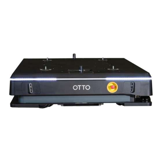
No modifications may be carried out that affect the integrated sensors or internal electronics. Figure 2 OTTO Motors AMR Isometric View © Clearpath Robotics Inc. 2021. All rights reserved. CLEARPATH and OTTO are trademarks of Clearpath Robotics Inc. All other product and company names listed are trademarks or trade names of their respective companies. -
Page 30: Figure 3 Otto 1500 V2.0 Amr Nameplate
OTT O 1 5 00 V 2 • O M M - 00 0 08 5 • R EV . D Figure 3 OTTO 1500 V2.0 AMR Nameplate Figure 4 OTTO 1500 V2.1 AMR Nameplate © Clearpath Robotics Inc. 2021. All rights reserved. CLEARPATH and OTTO are trademarks of Clearpath Robotics Inc. All other product and company names listed are trademarks or trade names of their respective companies. -
Page 31: Applicable Documents
Table 3 Applicable Documents REFERENCE NUMBER OTTO 1500 V2 AMR Operation and Maintenance Manual OMM-000085 OTTO 1500 V2 AMR Stability and Center of Gravity ICD-000090 OTTO 750/1500 V2 Manual Charger Operation and Maintenance Manual OMM-000089 OTTO 750/1500 Fast Charger Operation and Maintenance Manual... -
Page 32: In Case Of A Collision
Take photos or make a drawing. e. If the robot is connected to Fleet Manager, create a Manual Snapshot to capture diagnostic information and robot sensor data to assist OTTO Motors in diagnosing the incident cause. 4. Assess the state of the robot. -
Page 33: System Overview
OTT O 1 5 00 V 2 • O M M - 00 0 08 5 • R EV . D SYSTEM OVERVIEW This section provides an overview of the important elements of the OTTO Motors autonomous mobile robot (AMR) system. The following figures give a tour of the key components of the robot for basic use. - Page 34 X, Y + / - 25 mm (0.98 in) Yaw + / - 3 ° Positional accuracy is subject to the deployment. Please speak to your OTTO Motors representative for more information. Docking Accuracy X, Y + / - 10 mm (0.4 in) Yaw + / - 1 °...
- Page 35 OTT O 1 5 00 V 2 • O M M - 00 0 08 5 • R EV . D Battery Life 10,000 full charge cycles Control System Sensors 2 x 3D perception cameras 2 x LiDAR safety scanners Embedded 6-axis IMU Computer Solid-state military spec computer with Intel i7-6700TE Quad Core, 16 GB...
- Page 36 OTT O 1 5 00 V 2 • O M M - 00 0 08 5 • R EV . D Operating Environment Maximum Floor Slope 1° / 1.6 % Operating Environment Indoor IP Classification IP20 Operating Temperature 0°C to 40°C (32°F to 104°F) Range Non-Operating 0°C to 50°C (32°F to 122°F)
-
Page 37: Table 4 Lifepo4 Battery Technical Specifications
OTT O 1 5 00 V 2 • O M M - 00 0 08 5 • R EV . D Some specifications above are dependent on software and robot configuration. Please speak to your OTTO Motors representative for more information. Table 4 LiFePO4 Battery Technical Specifications... -
Page 38: Components Overview
The components overview is intended to familiarize the user with the separate components on the OTTO Motors autonomous mobile robot (AMR). Figure 5 OTTO Motors AMR Port and Front Figure 6 OTTO Motors AMR Starboard and Rear © Clearpath Robotics Inc. 2021. All rights reserved. CLEARPATH and OTTO are trademarks of Clearpath Robotics Inc. All other product and company names listed are trademarks or trade names of their respective companies. -
Page 39: Buttons And Ports
BURN or SHOCK HAZARD! Never use this product if the enclosure or any of the connectors are broken, cracked, open, or show any other indication of damage. See Attachment Interface for more detail. These documents are available on the OTTO Motors Support Center at help.ottomotors.com. -
Page 40: Figure 7 Lock Out/Tag Out Bay
OTT O 1 5 00 V 2 • O M M - 00 0 08 5 • R EV . D Lock Out/Tag Out Bay 8.1.3 The Lock Out/Tag Out Bay is located behind the Safety Reset and Power Buttons and contains the Lock Out/Tag Out switch that allows personnel to remove energy from the system. -
Page 41: Table 5 Safety Reset Button Light Indicator States
OTT O 1 5 00 V 2 • O M M - 00 0 08 5 • R EV . D Safety Reset Button 8.1.4 The Safety Reset button is located above the Power Button and is used by an operator to indicate that the robot is cleared for autonomous use. -
Page 42: Figure 8 Pendant And Manual Charge Port Bay
The Pendant and Manual Charge Bay is a triple-purpose bay that allows operators to connect the OTTO 750/1500 V2 Manual Charger or the pendant used for manual control of the robot, and includes storage for the manual bypass screws when they are not in use. To access the bay, push on the door. -
Page 43: Robot State Indicators
OTTO AMR. See the Basic Usage section of the operations and maintenance manual for the applicable OTTO AMR for instructions on changing robot volume settings. Table 6 OTTO Motors AMR light pipe patterns and indicated state NAME... - Page 44 OTT O 1 5 00 V 2 • O M M - 00 0 08 5 • R EV . D Charging The OTTO AMR is charging at a Charging Dock. Rear Corners Red Green Slowly Expanding indicating charge level Front Corners Orange The OTTO AMR has entered a Parked...
- Page 45 OTT O 1 5 00 V 2 • O M M - 00 0 08 5 • R EV . D Blocked The OTTO AMR is blocked from proceeding on its planned path. Front Flash Yellow Rear Solid Red Safety Stopped The OTTO AMR has been placed in a Safety Stop state.
-
Page 46: Pendant
See Attachment Interface and RQS-000006 - IT Infrastructure Requirements for more detail. These documents are available on the OTTO Motors Support Center at help.ottomotors.com. © Clearpath Robotics Inc. 2021. All rights reserved. CLEARPATH and OTTO are trademarks of Clearpath Robotics Inc. All other product and company names listed are trademarks or trade names of their respective companies. -
Page 47: Perception Sensors
OTT O 1 5 00 V 2 • O M M - 00 0 08 5 • R EV . D 8.6 Perception Sensors Safety LiDAR 8.6.1 WARNING! Failure to follow these instructions may result in SERIOUS INJURY, INCLUDING DEATH. CRUSH or IMPACT HAZARD! Keep low profile objects that the LiDAR cannot detect, such as forklift tines and pallets, outside of the robot's path. -
Page 48: Attachment Mounting And Lift Points
OTT O 1 5 00 V 2 • O M M - 00 0 08 5 • R EV . D at the center of each side. The swivel casters and drive wheels are connected to the rocker arms. This passive suspension system allows for the drive wheels to remain in contact with the ground during operation. -
Page 49: Figure 11 Live Voltage Locations
OTT O 1 5 00 V 2 • O M M - 00 0 08 5 • R EV . D WARNING! Failure to follow these instructions may result in SERIOUS INJURY, INCLUDING DEATH. SHOCK HAZARD! Always perform the Lock-Out Tag-Out procedure at the facility or on the product before inspecting, servicing, cleaning, removing components, or opening any enclosure. -
Page 50: Electronics Bay
OTT O 1 5 00 V 2 • O M M - 00 0 08 5 • R EV . D See the System Overview for battery system specifications. CAUTION! Failure to follow these instructions may result in MINOR or MODERATE INJURY or DAMAGE to the system and/or property. -
Page 51: Attachment Interface
See the Components Overview or RQS-000006 - IT Infrastructure Requirements for more detail. These documents are available on the OTTO Motors Knowledge Base under help.ottomotors.com. © Clearpath Robotics Inc. 2021. All rights reserved. CLEARPATH and OTTO are trademarks of Clearpath Robotics Inc. All other product and company names listed are trademarks or trade names of their respective companies. -
Page 52: Mechanical Interface Specifications
See the mechanical interface documentation for the robot for more detail. These documents are available on the OTTO Motors Support Center at help.ottomotors.com. © Clearpath Robotics Inc. 2021. All rights reserved. CLEARPATH and OTTO are trademarks of Clearpath Robotics Inc. All other product and company names listed are trademarks or trade names of their respective companies. -
Page 53: Electrical Interface Specifications
OTT O 1 5 00 V 2 • O M M - 00 0 08 5 • R EV . D The current concept for each of the four mounting points is a mounting pad with four bolts and a center locating feature. -
Page 54: Table 7 Attachment Electrical Interfaces
OTT O 1 5 00 V 2 • O M M - 00 0 08 5 • R EV . D Attachment Interface Signals 9.3.1 Table 7 Attachment Electrical Interfaces INTERFACE VOLTAGE NOTES Emergency Stop Dual-channel Emergency Stop from attachment to base Input platform. -
Page 55: Figure 15 Attachment Interface Signals Timing Diagram
OTT O 1 5 00 V 2 • O M M - 00 0 08 5 • R EV . D Battery Power 44.8VDC (min.) Unregulated, switched, up to 50A, 51.2V nominal. The Battery Power line is switched by the attachment contactor in the 60VDC (max.) base platform and is switched immediately upon the Emergency Stop chain being broken. -
Page 56: Figure 16 Attachment Interface Connectors
OTT O 1 5 00 V 2 • O M M - 00 0 08 5 • R EV . D Unswitched vs. Switched Power for Non-Safety Devices 9.3.2 There are 2 different power supplies available in the attachment Interface: 24 VDC and battery voltage. In general, attachments should use the unswitched 24VDC power from the robot attachment interface for attachment logic power and inputs required to determine attachment states that could affect the safe operation of the robot. -
Page 57: Figure 17 Attachment Interface Connector Decal
OTT O 1 5 00 V 2 • O M M - 00 0 08 5 • R EV . D To assist in identifying the attachment interface connector types, the robot attachment interface includes the following decal. Figure 17 Attachment Interface Connector Decal 24-Pin Connector 9.3.3.1 Table 8 Attachment Interface 24-Pin Connector Part Numbers... -
Page 58: Table 9 Attachment Interface 12-Pin Connector Part Numbers
OTT O 1 5 00 V 2 • O M M - 00 0 08 5 • R EV . D 12-Pin Connector 9.3.3.2 Table 9 Attachment Interface 12-Pin Connector Part Numbers PART MANUFACTURER DESCRIPTION NUMBER Robot Side DT04-12PA- TE Connectivity Connector, DT Series, Panel, Receptacle, 12 Positions, 2 Rows, L012 Rectangular, Sealed... -
Page 59: Table 11 Attachment Interface Ethernet, Usb & Hdmi Parts
OTT O 1 5 00 V 2 • O M M - 00 0 08 5 • R EV . D PM16S1620S32- Anderson Power SBS75x Auxiliary Socket, #20-16 AWG (0.75-1.0mm) Products Ethernet, USB and HDMI 9.3.3.4 Table 11 Attachment Interface Ethernet, USB & HDMI Parts DESCRIPTION Robot Side Standard RJ45 Jack... -
Page 60: Safety Relay And Auxiliary Monitoring Contacts
OTT O 1 5 00 V 2 • O M M - 00 0 08 5 • R EV . D 9.4 Safety Relay and Auxiliary Monitoring Contacts The below figure illustrates the electrical connection available on the robot attachment interface and connection of a typical safety relay with auxiliary monitoring contacts. -
Page 61: Table 12 Robot Side 24-Pin Connector Pin-Out Functions (Wire Entry Side)
OTT O 1 5 00 V 2 • O M M - 00 0 08 5 • R EV . D Table 12 Robot Side 24-Pin Connector Pin-Out Functions (wire entry side) NAME NOTES PA_24V 24V, 10A total available across all connections Note that this is not fused power. - Page 62 OTT O 1 5 00 V 2 • O M M - 00 0 08 5 • R EV . D PA_GPI_0 General purpose in 0 (SDV_ENABLE) (SDV_ENABLE) GPI_0 is used to signal to the AMR from the attachment that the robot is able to move after it has given control to the attachment Attachment to use dry contact between PA_24V and input.
-
Page 63: Figure 20 Robot Side 12-Pin Connector Pin-Out Functions
OTT O 1 5 00 V 2 • O M M - 00 0 08 5 • R EV . D Robot Side 12-Pin Connector 9.5.2 The pin-out numbering for the 12-pin connector is as shown below. Figure 20 Robot Side 12-Pin Connector Pin-Out Functions Table 13 12-Pin Connector Pin-Out Descriptions (wire entry side) NAME NOTES... -
Page 64: Figure 21 Robot Side Sbs75 Pin-Out Details
OTT O 1 5 00 V 2 • O M M - 00 0 08 5 • R EV . D Attachment to use dry contact between PA_24V and input. PA_GPI_4 General purpose in 4 Attachment to use dry contact between PA_24V and input. PA_GPO_3 General purpose out 3, PNP sourcing output, 500mA max. -
Page 65: Figure 22 Attachment Side Minimum Connections For Passive Attachment
OTT O 1 5 00 V 2 • O M M - 00 0 08 5 • R EV . D Minimum Required Connections 9.5.4 Passive Attachment 9.5.4.1 Passive attachments to not draw power from the base robot chassis. • Emergency stop loop is closed. -
Page 66: Figure 23 Attachment Side Minimum Connections For Active Attachment
OTT O 1 5 00 V 2 • O M M - 00 0 08 5 • R EV . D Active Attachment 9.5.4.2 Active attachments will draw power from the base robot chassis. • Emergency stop loop is closed •... -
Page 67: Attachment Interface Examples
OTT O 1 5 00 V 2 • O M M - 00 0 08 5 • R EV . D General Purpose Inputs 9.5.6 The 24V Inputs, PNP type use the form shown below and must adhere to the following voltage requirements: Table 15 General Purpose Input Voltage Requirements PIN INPUT VOLTAGE... -
Page 68: Figure 24 Conveyor-Style Attachment Safety Interface
OTT O 1 5 00 V 2 • O M M - 00 0 08 5 • R EV . D 24 VDC Unswitched, up to 10A Ethernet Attachment 100 Mbps Ethernet connection using Ethernet/IP Figure 24 Conveyor-Style Attachment Safety Interface Lift-Style Attachment Interface Signal Example 9.6.2 Table 17 Lift-Style Attachment Safety Interface... - Page 69 OTT O 1 5 00 V 2 • O M M - 00 0 08 5 • R EV . D Attachment Fault Input from attachment indicating that the attachment has encountered a Status problem If a fault is indicated on this input, the AMR will cease autonomous operation and indicate that it needs an operator to examine the attachment.
-
Page 70: Unboxing
OTT O 1 5 00 V 2 • O M M - 00 0 08 5 • R EV . D UNBOXING Selection and implementation of the lifting method appropriate for the situation, and liability therefor, remains the sole responsibility of the user. Only certified forklift operators should attempt lifting the robot. -
Page 71: Procedure
Manual for the specific attachment (OTTO 750/1500 Lift Attachment, OTTO 750/1500 Conveyor Attachment, etc.) for more detail on lifting methods. These documents are available on the OTTO Motors Knowledge Base under help.ottomotors.com. 3. Loop a Web Sling through each Eye Bolt/Eye Nut and secure to the lifting device. -
Page 72: Basic Usage
This section describes the operation of the robot. Prior to using the robot, the surrounding area must be approved for autonomous navigation by an OTTO Motors representative. Never use the robot in an area without prior consultation by an OTTO Motors representative. -
Page 73: Figure 26 Pendant And Manual Charge Port Bay
OTT O 1 5 00 V 2 • O M M - 00 0 08 5 • R EV . D Figure 26 Pendant and manual charge port bay lock-out/tag-out The lock on the lock-out bracket above the Manual Charge Port must be threaded through both holes on the bracket, as shown below: All personnel working on the platform must connect their own lock. -
Page 74: First Start-Up
Only use the attachments, accessories, tools, replacement parts, and cleaning products approved by OTTO Motors. Prior to operating the robot for the first time, it is important to perform a hardware operational check to determine if there is any hardware damage or defects caused during shipping. -
Page 75: Starting Up
If the robotR takes more than 6 minutes to boot or never indicates an Emergency Stop state during start up, contact OTTO Motors Support for assistance. © Clearpath Robotics Inc. 2021. All rights reserved. CLEARPATH and OTTO are trademarks of Clearpath Robotics Inc. All other product and company names listed are trademarks or trade names of their respective companies. -
Page 76: Shutting Down
OTT O 1 5 00 V 2 • O M M - 00 0 08 5 • R EV . D 11.4 Shutting Down Note that when cycling power, the robot should be given at least 5 minutes between each state change (power on or power off). - Page 77 OTT O 1 5 00 V 2 • O M M - 00 0 08 5 • R EV . D If the robot included an OTTO 750/1500 Charger/Fast Charger V2, vehicles will be sent to charge autonomously without human intervention. The robot will shut itself down at 20 - 25% battery state-of- charge.
-
Page 78: Moving
OTT O 1 5 00 V 2 • O M M - 00 0 08 5 • R EV . D 11.6 Moving WARNING! Failure to follow these instructions may result in SERIOUS INJURY, INCLUDING DEATH. Always use level rigging when lifting or lowering the product. IMPACT HAZARD! Never bypass the drive wheels of the robot while on a sloped surface. -
Page 79: Storage
OTT O 1 5 00 V 2 • O M M - 00 0 08 5 • R EV . D Disengaging Drive Wheel Manual Bypass 11.6.3 1. Using a 15 mm 12-point socket, turn the manual bypass screws counter-clockwise until the drive wheels regain contact with the floor. -
Page 80: Figure 27 Linux Ifconfig
OTT O 1 5 00 V 2 • O M M - 00 0 08 5 • R EV . D Linux 11.8.2.1 1. From the system tray, click the Network Manager icon and select Edit Connections. The Network Connections screen is displayed. 2. -
Page 81: Figure 28 Windows 10 Tcp/Ipv4 Properties
OTT O 1 5 00 V 2 • O M M - 00 0 08 5 • R EV . D Figure 28 Windows 10 TCP/IPv4 Properties 5. In the IP address field, use the above network address and netmask. 6. -
Page 82: Figure 30 Otto Amr Ping Result
Table 18 Robot IP Addresses ROBOT MODEL IP ADDRESS OTTO 750/1500 V1.2 SDV 10.255.255.1 OTTO 750/1500 V2 SDV 10.253.253.1 You should receive a response similar to the following: Figure 30 OTTO AMR Ping Result • If configuring a single OTTO AMR that will not be added to a fleet using the OTTO Fleet Manager software, connect the robot to the network. -
Page 83: Connecting The Robot To The Network
5 GHz wireless frequencies. 5 GHz is strongly recommended as the 2.4 GHz frequency may result in performance issues. If 2.4 GHz is required for the robot to connect, please contact your OTTO Motors representative to assist in changing the robot's configuration. -
Page 84: Otto App
OTT O 1 5 00 V 2 • O M M - 00 0 08 5 • R EV . D 11.10 OTTO App OTTO App can be used to wirelessly control a robot if it's already connected to a wireless network. OTTO™... - Page 85 Manual Snapshot The Create New Manual Snapshot button is used to create manual snapshot files used for diagnostics by OTTO Motors Support staff. 4. Select Save to save any changes you've made. © Clearpath Robotics Inc. 2021. All rights reserved. CLEARPATH and OTTO are trademarks of Clearpath Robotics Inc. All other product and company names listed are trademarks or trade names of their respective companies.
-
Page 86: Driving An Otto Amr Manually
OTT O 1 5 00 V 2 • O M M - 00 0 08 5 • R EV . D CAUTION! Failure to follow these instructions may result in MINOR or MODERATE INJURY or DAMAGE to the system and/or property. IMPACT HAZARD! While driving the robot manually, the safety fieldsets monitored by the LiDAR scanners are disabled. -
Page 87: Magnetic Line Following
OTT O 1 5 00 V 2 • O M M - 00 0 08 5 • R EV . D To adjust the top speed at which an OTTO AMR will travel, use the Speed slider. OTTO AMRs will drive slower the lower the slider is set and robot field sets will narrow for easier navigation around close objects. -
Page 88: Driving An Otto Amr Autonomously
OTT O 1 5 00 V 2 • O M M - 00 0 08 5 • R EV . D OTTO AMRs will not be affected by Preferred Direction or Assumed Cost (with a cost less than 1.0) zones when operating under Drive Assist control. These zones influence the path that the robot would prefer to take and said path is being commanded manually by the user in this mode. -
Page 89: Driving With Markers
OTT O 1 5 00 V 2 • O M M - 00 0 08 5 • R EV . D 8. Select Go to send the OTTO AMR on its way. A "Moving" notification is displayed. 9. Select Stop to stop the OTTO AMR at any time. You can select the Drive Mode toggle at any point to enter Manual drive mode. -
Page 90: Driving Using The Pendant
OTT O 1 5 00 V 2 • O M M - 00 0 08 5 • R EV . D 11.16 Driving using the Pendant CAUTION! Failure to follow these instructions may result in MINOR or MODERATE INJURY or DAMAGE to the system and/or property. - Page 91 OTT O 1 5 00 V 2 • O M M - 00 0 08 5 • R EV . D 2. Confirm that all Emergency Stop buttons on the robot, pendant, and any equipped attachment are released. 3. On the Pendant, press and hold the black Enable button in the middle ON position. 4.
-
Page 92: Maintenance
OTT O 1 5 00 V 2 • O M M - 00 0 08 5 • R EV . D MAINTENANCE Failure to follow the maintenance checks and intervals outlined below could lead to unsafe conditions. Table 19 Maintenance Schedule COMPONENT DAILY WEEKLY... -
Page 93: Figure 32 Lock-Out/Tag-Out Bay Lock-Out Off Position
OTT O 1 5 00 V 2 • O M M - 00 0 08 5 • R EV . D 1. Shut down the robot. 2. Wait until the light pipes have completely turned off. 3. Find and open the Lock Out/Tag Out Bay. 4. -
Page 94: Maintenance Safety
OTT O 1 5 00 V 2 • O M M - 00 0 08 5 • R EV . D WARNING! Failure to follow these instructions may result in SERIOUS INJURY, INCLUDING DEATH. SHOCK HAZARD! Always perform the Lock-Out Tag-Out procedure at the facility or on the product before inspecting, servicing, cleaning, removing components, or opening any enclosure. -
Page 95: Daily Preventative Maintenance
OTT O 1 5 00 V 2 • O M M - 00 0 08 5 • R EV . D • NEVER bypass or use a jumper to replace any limit switch, fuse, circuit breaker, or other circuit protection or safety device. •... - Page 96 12.3.2.1 • Flashlight • Antifog/Antistatic Lens Cleaning Wipes (OTTO Motors Part Number 015591) CAUTION! Failure to follow these instructions may result in MINOR or MODERATE INJURY or DAMAGE to the system and/or property. SHOCK HAZARD! Always perform the Lock-Out Tag-Out procedure at the facility or on the product before inspecting, servicing, cleaning, removing components, or opening any enclosure.
-
Page 97: Weekly Preventative Maintenance
12.4.1.1 • Flashlight • Antifog/Antistatic Lens Cleaning Wipes (OTTO Motors Part Number 015591) CAUTION! Failure to follow these instructions may result in MINOR or MODERATE INJURY or DAMAGE to the system and/or property. SHOCK HAZARD! Always perform the Lock-Out Tag-Out procedure at the facility or on the product before inspecting, servicing, cleaning, removing components, or opening any enclosure. - Page 98 OTT O 1 5 00 V 2 • O M M - 00 0 08 5 • R EV . D Required Materials 12.4.2.1 • Robot experiencing a battery SOC misalignment • OTTO 750/1500 Fast Charger V2 • Laptop or tablet connected to the same network as the robot •...
-
Page 99: Monthly Preventative Maintenance
If the robot continues to experience issues with battery performance after completing this calibration procedure, contact OTTO Motors Support for further direction. 12.5 Monthly Preventative Maintenance Perform the following tasks once every month: Exterior Cleaning 12.5.1... - Page 100 OTT O 1 5 00 V 2 • O M M - 00 0 08 5 • R EV . D • Be cautious to avoid the power and Emergency Stop buttons, as well as the Attachment Interface. • Do not rub aggressively on any stickers or number decals. 4.
- Page 101 This process will perform a battery calibration as well. If only SoC drift is the issue, follow the Battery Calibration procedure. Required Materials 12.5.4.1 To perform this maintenance, you will require the following: • OTTO 750/1500 V2 AMR • OTTO 750/1500 Fast Charger V2 • OTTO 750/1500 Manual Charger V2 •...
- Page 102 If the robot continues to experience issues with battery performance after completing this calibration procedure, contact OTTO Motors Support for further direction. Post-Maintenance 12.5.4.4 1.
-
Page 103: Disposal
OTT O 1 5 00 V 2 • O M M - 00 0 08 5 • R EV . D DISPOSAL Always observe environmental protection regulations valid to your region. If disassembling the robot for disposal, pass on any commercially-viable disassembled components for recycling. -
Page 104: Troubleshooting
First, check that the circuit breaker is enabled. Next, press the Power Button momentarily. If neither of the above work, connect the OTTO 750/1500 V2 Manual Charger to recover the battery. The charge cycle will not complete if a LiDAR Safety Stop is triggered in the Robot stuck in charger Dock. - Page 105 Check that a valid LiDAR field set and Safety Configuration are loaded onto the OTTO AMR. Talk to OTTO Motors Support for instructions on diagnosing a blown traction motor fuse. The Safety Configuration will include information about the space required by the OTTO AMR for autonomous navigation.
-
Page 106: Declarations
Machine name: Autonomous Mobile Robot (AMR) Model: OTTO 1500 V2 Serial number(s): B10-XXXX200XX manufactured by: Clearpath Robotic Inc. dba OTTO Motors 124 Bleams Road Kitchener, ON – N2C 2K5 Canada to which this declaration relates, is in conformity with the following European Directives... -
Page 107: Supplier's Declaration Of Conformity
OTT O 1 5 00 V 2 • O M M - 00 0 08 5 • R EV . D 15.2 Supplier’s Declaration of Conformity 47 CFR § 2.1077 Compliance Information OTTO 1500 V2 Responsible Party: Clearpath US One Marina Park Drive, 10th Floor... -
Page 108: Can Ices-003(A) / Nmb-003(A)
OTT O 1 5 00 V 2 • O M M - 00 0 08 5 • R EV . D 15.3 CAN ICES-003(A) / NMB-003(A) Issue 6 January 2016 Contains Transmitter Module IC: 1000M-AX200NG © Clearpath Robotics Inc. 2021. All rights reserved. CLEARPATH and OTTO are trademarks of Clearpath Robotics Inc. All other product and company names listed are trademarks or trade names of their respective companies. - Page 109 OTT O 1 5 00 V 2 • O M M - 00 0 08 5 • R EV . D These are important Safety Instructions and should be saved for reference. Original instructions provided in English. < END OF DOCUMENT > ©...
Need help?
Do you have a question about the 1500 V2 and is the answer not in the manual?
Questions and answers