Table of Contents

Subscribe to Our Youtube Channel
Related Manuals for Teleflex Marine SeaSTAR OPTIMUS Steering System


Summary of Contents for Teleflex Marine SeaSTAR OPTIMUS Steering System
- Page 1 operation instructions MEMBER and users manual w w w . t e l e f l e x m a r i n e . c o m i s o 9 0 0 1 Electronic Power Steering for Outboard Powered Vessels MANUFACTURED BY MARiNE CANADA ACQUisiTioN LiMiTED...
- Page 2 For the latest information, go to www.teleflexmarine.com All Rights Reserved: No part of this publication may be reproduced or used in any form by any means without the written permission of Teleflex Marine Incorporated. ©2012 Teleflex Marine. is a registered trademark of the American Boat & Yacht Council (http://www.abycinc.org)
- Page 3 SEVErE PErSOnaL injury Or dEath. cautiOn hazards or unsafe practices which cOuLd result in minor injury or product or property damage. Information which is important to proper use or maintenance, but is not hazard-related. © 2012 Teleflex Marine, Inc. Optimus Operations Manual, Rev. A...
-
Page 4: Table Of Contents
9.1 SeaStar Electronic Power Steering Fluid ....... 40 10. warranty ................41 10.1 Statement of Limited Warranty ........41 10.2 Return Goods Procedure .......... 41 aPPEndiX a - Specifications ............. 42 © 2012 Teleflex Marine, Inc. Optimus Operations Manual, Rev. A... -
Page 5: Safety Instructions
5. Verify proper shift and throttle response for all control handles. 6. Verify that no alarms or warnings are shown on the CANtrak display. dO nOt OPEratE bOat if any cOmPOnEnt iS nOt in PrOPEr wOrking cOnditiOn. © 2012 Teleflex Marine, Inc. Optimus Operations Manual, Rev. A... - Page 6 Maintain Optimus Steering System as directed in Section 7 of this Manual. Keep our waters clean for all current and future users. Dispose of ALL fluids in accordance with your local regulations. © 2012 Teleflex Marine, Inc. Optimus Operations Manual, Rev. A...
-
Page 7: Safety Labels
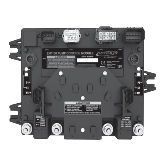
(see Section 3.1) hydraulic Pump Label CAUTION Pump control module (Pcm) Label © 2012 Teleflex Marine, Inc. Optimus Operations Manual, Rev. A... - Page 8 Safety Labels Continued Smartcylinder Label Steering Service Valve Label (may be installed if the valve is hidden from view.) © 2012 Teleflex Marine, Inc. Optimus Operations Manual, Rev. A...
-
Page 9: Abbreviations
The special protocol for digital communication on a ® CAN Bus Revolutions Per Minute STBD Starboard (right) Note: Some abbreviations not listed here may be found in their respective sections. © 2012 Teleflex Marine, Inc. Optimus Operations Manual, Rev. A... -
Page 10: Introduction
The Optimus EPS system includes many advancements to make the system as failsafe as possible. These include redundant sensors, fault-tolerant communications, self-monitoring and fault communications to notify and advise the operator in case of fault. © 2012 Teleflex Marine, Inc. Optimus Operations Manual, Rev. A... -
Page 11: Optimus Eps System Diagram
2.3 Optimus EPS System Diagram © 2012 Teleflex Marine, Inc. Optimus Operations Manual, Rev. A... -
Page 12: First Time Operation
Check near the batteries, in the circuit breaker box, or near the Pump Control Modules or Hydraulic Pumps. There should be a 60 amp breaker for each PCM power feed. © 2012 Teleflex Marine, Inc. Optimus Operations Manual, Rev. A... - Page 13 SeaStar Electronic Power Steering Fluid. The pumps have the steering fluid reservoir and this is where the fluid level is checked and steering fluid is added. © 2012 Teleflex Marine, Inc. Optimus Operations Manual, Rev. A...
- Page 14 EPS system failure. Instructions on how to proceed will be supplied on the CANtrak display or in Section 6.2.5. wARNiNg wear a coast guard-approved personal flotation device (Pfd) when manually realigning engines. © 2012 Teleflex Marine, Inc. Optimus Operations Manual, Rev. A...
- Page 15 3.1.7 Cantrak Display There is a display at each helm station that shows the system status and allows system adjustments. © 2012 Teleflex Marine, Inc. Optimus Operations Manual, Rev. A...
-
Page 16: Initial Start Up
On multiple helm station boats all helms are active when the Optimus EPS is turned on. this is the same you would find on a conventional hydraulic steering system. © 2012 Teleflex Marine, Inc. Optimus Operations Manual, Rev. A... -
Page 17: System Inspection
Check all electrical and mechanical cabling for abrasion, wear, rubbing or chafing. Check that all connections are tight and free of corrosion. © 2012 Teleflex Marine, Inc. Optimus Operations Manual, Rev. A... - Page 18 © 2012 Teleflex Marine, Inc. Optimus Operations Manual, Rev. A...
-
Page 19: Installation Checks
UP. Turn the steering wheel from hard over to hard over and confirm that no interference occurs. cautiOn If any issues are found during the installation checks, immediately return the boat to the service dealer for those issues to be remedied. © 2012 Teleflex Marine, Inc. Optimus Operations Manual, Rev. A... - Page 20 Installation Checks continued Make sure that all cables and hoses move freely and that the cylinders and engines are clear at steering extremes. EnginE SidE ViEw, whEn tiLtEd © 2012 Teleflex Marine, Inc. Optimus Operations Manual, Rev. A...
- Page 21 2. Sensor cable - Confirm that the SmartCylinder Sensor Cable is tied securely to the hoses with gradual bends as shown in the following diagrams. tiES SEcurEd tO fittingS SmOOth bEnd nO kinking tiES nO mOrE than 6” aPart © 2012 Teleflex Marine, Inc. Optimus Operations Manual, Rev. A...
-
Page 22: Initial Sea Trial
If settings require adjustment during the sea trial, refer to Section 5.0 for further details. © 2012 Teleflex Marine, Inc. Optimus Operations Manual, Rev. A... -
Page 23: System Use
CAUTioN On multiple helm station boats all helms are active when the Optimus EPS is turned on. This is the same you would find on a conventional hydraulic steering system. © 2012 Teleflex Marine, Inc. Optimus Operations Manual, Rev. A... -
Page 24: Multiple Stations
See your autopilot user’s manuals for specific system behavior. wARNiNg never leave the helm station unattended when the autopilot is engaged. The Title Bar will display “Autopilot Mode” when the autopilot is engaged. © 2012 Teleflex Marine, Inc. Optimus Operations Manual, Rev. A... -
Page 25: Cantrak Display
Instructs the operator what to do in case of a system fault. 3. Permits changes to the basic system settings. 4. Provides system and diagnostic information For details on CANtrak operation see sections 5.2 through 5.4 of this manual. © 2012 Teleflex Marine, Inc. Optimus Operations Manual, Rev. A... -
Page 26: Cantrak Display Navigation
Increases the setting of a selected item Accepts a given statement or condition and advances to the next screen Moves the unit back one level. CANtrak display lighting CANtrak display contrast © 2012 Teleflex Marine, Inc. Optimus Operations Manual, Rev. A... -
Page 27: Cantrak Display Map - All Helms Active
All Helms Active DIAGNOSTICS Network nodes Node Information ADjUST LO Speed Helm Turns HI Speed Helm Turns LO Speed Helm Effort HI Speed Helm Effort AP Helm Effort DISPLAY Contrast Brightness © 2012 Teleflex Marine, Inc. Optimus Operations Manual, Rev. A... -
Page 28: All Helms Active Screens
Diagnostics, Adjustment and Display menu screens. 5.4.2 Diagnostics (DIaG) Screen The Diagnostics screen allows the user the access to basic system diagnostics tools including network node information and a CAN message viewer. diagnostics Screen © 2012 Teleflex Marine, Inc. Optimus Operations Manual, Rev. A... - Page 29 Engaged Steering Effort This setting increases the steering resistance slightly when autopilot is engaged to prevent accidental course corrections with the wheel. It is adjustable between 0 and 100. © 2012 Teleflex Marine, Inc. Optimus Operations Manual, Rev. A...
- Page 30 CAUTioN Adjusting steering effort for steering turns can significantly impact boat handling. Proceed with caution after making any changes. © 2012 Teleflex Marine, Inc. Optimus Operations Manual, Rev. A...
- Page 31 Display (DISP) Screen The Display screen allows adjustment of the brightness and contrast of the CANtrak display. These should be adjusted to provide good daytime and night time visibility of the display. © 2012 Teleflex Marine, Inc. Optimus Operations Manual, Rev. A...
-
Page 32: System Faults & Hazards
In the case of a warning fault, the CANtrak buzzer will sound intermittently (until muted) and the CANtrak will display the Warning screen. See Section 6.2.3 for warning fault handling specifics. © 2012 Teleflex Marine, Inc. Optimus Operations Manual, Rev. A... -
Page 33: System Fault Handling
Provides detailed instructions on how to proceed. In the case of a danger fault, this will instruct the operator what to do and how to proceed should Limp Home mode be required. © 2012 Teleflex Marine, Inc. Optimus Operations Manual, Rev. A... - Page 34 ANY of the engines. The CANtrak will instruct the operator to manually realign the engines using the service valves, and proceed home immediately using the shift and throttle controls to control the vessel as shown in the figure below. © 2012 Teleflex Marine, Inc. Optimus Operations Manual, Rev. A...
- Page 35 ONE of the engines. The CANtrak will instruct the operator to realign the non-responsive engine, tilt it out of the water and proceed home immediately using the responsive engine as shown in the figure below. © 2012 Teleflex Marine, Inc. Optimus Operations Manual, Rev. A...
- Page 36 © 2012 Teleflex Marine, Inc. Optimus Operations Manual, Rev. A...
- Page 37 ScrEEn with SyStEm warning Some system faults may result in a reduced steering response warning. This means that the system will continue to steer normally but may respond slower. © 2012 Teleflex Marine, Inc. Optimus Operations Manual, Rev. A...
- Page 38 It also informs the user that the system has switched to the starboard battery and reduced the steering speed. The vessel should be returned to port immediately for repair. © 2012 Teleflex Marine, Inc. Optimus Operations Manual, Rev. A...
- Page 39 2. Put engine(s) in Neutral. 3. Open Steering Service Valves. 4. Turn affected engine fully away from other. 5. Close Steering Service Valves 6. Fully tilt affected engine. 7. Return to port. © 2012 Teleflex Marine, Inc. Optimus Operations Manual, Rev. A...
-
Page 40: Buzzer
If any of the above are used in the system, then the system should be flushed and refilled with SeaStar Electronic Power steering fluid when the boat is returned to port. never use brake fluid. © 2012 Teleflex Marine, Inc. Optimus Operations Manual, Rev. A... -
Page 41: Maintenance
3. Check for mechanical play or slop throughout steering system, correct as required. 4. Check for signs of corrosion. If corrosion is present contact your dealer or Teleflex Marine. 5. Check all electrical cables for chaffing and wear. © 2012 Teleflex Marine, Inc. Optimus Operations Manual, Rev. A... - Page 42 GREASE SUPPORT ROD, TILT TUBE & SUPPORT BRACKET HOLE GREASE SUPPORT ROD, TILT TUBE & SUPPORT BRACKET HOLE © 2012 Teleflex Marine, Inc. Optimus Operations Manual, Rev. A...
-
Page 43: Troubleshooting
Check circuit breaker for the engine. Reset breaker. If it immediately trips not steer, but a second time look for a shorted or cantrak display is pinched wire or failed component. © 2012 Teleflex Marine, Inc. Optimus Operations Manual, Rev. A... -
Page 44: Replacement Parts
9.0 replacement parts 9.1 SeaStar Electronic Power Steering Fluid Quart HA5482 Gallon HA5483 For full listing of part numbers, please refer to the Optimus 50 Installation Manual, part no. 682100. © 2012 Teleflex Marine, Inc. Optimus Operations Manual, Rev. A... -
Page 45: Warranty
RGA # ? Teleflex Canada Teleflex Canada c/o UPS-Supply Chain Solutions, Inc. 3831 No. 6 Road Door A37 Richmond, B.C. 1201 C Street NW Canada V6V 1P6 Auburn, WA 98001 © 2012 Teleflex Marine, Inc. Optimus Operations Manual, Rev. A... -
Page 46: Appendix A - Specifications
Operating Voltage: 12Vdc Maximum System Pressure: 1200 PSI # of wheel turns: Variable from 3.5 to 8 Typical Average Current Draw: ~6 to 8 Amps Oil Type: SeaStar Electronic Power Steering Fluid © 2012 Teleflex Marine, Inc. Optimus Operations Manual, Rev. A... - Page 47 © 2012 Teleflex Marine, Inc. Optimus Operations Manual, Rev. A...
- Page 48 TELEFLEX CANADA 3831 NO. 6 ROAD RICHMOND, B.C. CANADA V6V 1P6 PHONE: 604-248-3858 FAX: 604-279-2202 WEB: www.teleflexmarine.com iso 10592 © 2012 MARINE CANADA ACQUISITION LIMITED PARTNERSHIP DBA TELEFLEX CANADA PRINTED IN CANADA PART NO. 682101, REVISION A...
Need help?
Do you have a question about the SeaSTAR OPTIMUS Steering System and is the answer not in the manual?
Questions and answers