
Related Manuals for Asus AAEON UP-POEV2-30W


Summary of Contents for Asus AAEON UP-POEV2-30W
- Page 1 UP PoE V2 Expansion Board Maker Board UP-POEV2-30W User’s Manual 1st Ed Last Updated: March 24, 2023...
- Page 2 Copyright Notice This document is copyrighted, 2023. All rights are reserved. The original manufacturer reserves the right to make improvements to the products described in this manual at any time without notice. No part of this manual may be reproduced, copied, translated, or transmitted in any form or by any means without the prior written permission of the original manufacturer.
- Page 3 Acknowledgement Microsoft®, Windows® are registered trademarks of Microsoft Corp All other products’ name or trademarks are properties of their respective owners. Preface...
- Page 4 Packing List Before setting up your product, please make sure the following items have been shipped: Item Quantity UP POEV2 Carrier Board ⚫ FPC Cable ⚫ Power Cable ⚫ (DC Jack 5.5x2.1mm to 3.96mm 1*2P housing.200mm) Screw/Stud Pack ⚫ If any of these items are missing or damaged, please contact your distributor or sales representative immediately.
- Page 5 About this Document This User’s Manual contains all the essential information, such as detailed descriptions and explanations on the product’s hardware and software features (if any), its specifications, dimensions, jumper/connector settings/definitions, and driver installation instructions (if any), to facilitate users in setting up their product. Users may refer to the product page at AAEON.com for the latest version of this document.
- Page 6 Safety Precautions Please read the following safety instructions carefully. It is advised that you keep this manual for future references All cautions and warnings on the device should be noted. Make sure the power source matches the power rating of the device. Position the power cord so that people cannot step on it.
- Page 7 If any of the following situations arises, please the contact our service personnel: Damaged power cord or plug Liquid intrusion to the device iii. Exposure to moisture Device is not working as expected or in a manner as described in this manual The device is dropped or damaged Any obvious signs of damage displayed on the device...
- Page 8 FCC Statement This device complies with Part 15 FCC Rules. Operation is subject to the following two conditions: (1) this device may not cause harmful interference, and (2) this device must accept any interference received including interference that may cause undesired operation.
- Page 9 China RoHS Requirements (CN) 产品中有毒有害物质或元素名称及含量 AAEON Main Board/ Daughter Board/ Backplane 有毒有害物质或元素 部件名称 铅 汞 镉 六价铬 多溴联苯 多溴二苯醚 (Pb) (Hg) (Cd) (Cr(VI)) (PBB) (PBDE) 印刷电路板 ○ ○ ○ ○ 及其电子组件 外部信号 ○ ○ ○ ○ 连接器及线材 O:表示该有毒有害物质在该部件所有均质材料中的含量均在 SJ/T 11363-2006 标准规定的限量要求以下。 X:表示该有毒有害物质至少在该部件的某一均质材料中的含量超出...
- Page 10 China RoHS Requirement (EN) Poisonous or Hazardous Substances or Elements in Products AAEON Main Board/ Daughter Board/ Backplane Poisonous or Hazardous Substances or Elements Hexavalent Polybrominated Polybrominated Component Lead Mercury Cadmium Chromium Biphenyls Diphenyl Ethers (Pb) (Hg) (Cd) (Cr(VI)) (PBB) (PBDE) PCB &...
-
Page 11: Table Of Contents
Table of Contents Chapter 1 - Product Specifications..................1 Specifications ......................2 Chapter 2 – Hardware Information ..................3 Dimensions ....................... 4 Board Layout ......................5 List of Jumpers and Connectors ................6 2.3.1 FPC/FFC Connector (CN1)................7 2.3.2 USB/UART Wafer (CN3) ................8 2.3.3 Power Output (12V) (CN6) ................. -
Page 12: Chapter 1 - Product Specifications
Chapter 1 Chapter 1 - Product Specifications... -
Page 13: Specifications
Specifications System PoE Spec POE+ (IEEE 802.3at Type 2) Ethernet 10/100/1000GbE Base External Ports RJ-45 x 1 USB 3.2 Gen 1 x 1 Internal Connector 41-pin FPC Connector x 1 10-pin Wafer x 1 Dimension 3.37" x 2.22" (85mm x 56mm) Net Weight 0.09 lb. -
Page 14: Chapter 2 - Hardware Information
Chapter 2 – Hardware Information Chapter 2... -
Page 15: Dimensions
Dimensions Chapter 2 – Hardware Information... -
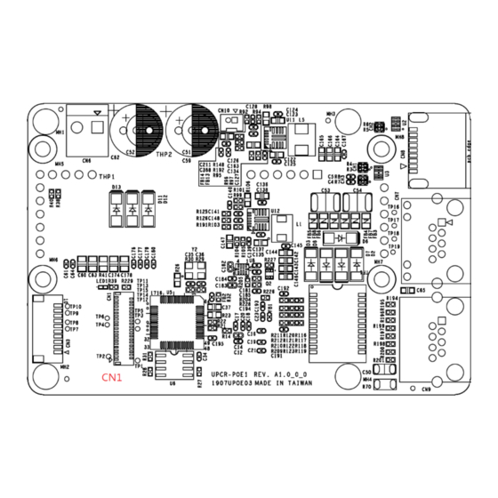
Page 16: Board Layout
Board Layout Chapter 2 – Hardware Information... -
Page 17: List Of Jumpers And Connectors
List of Jumpers and Connectors Label Functional Description FPC/FFC Connector USB/UART Wafer Power Output (12V) PoE LAN Port USB 3.2 Gen 1 Port CN10 Fan Connector (Optional) Chapter 2 – Hardware Information... -
Page 18: Fpc/Ffc Connector (Cn1)
2.3.1 FPC/FFC Connector (CN1) Signal Description Signal Description USB3 RX_N USB3 RX_P USB3 TX_N USB3 TX_P USB2 DN USB2 DP PCIE Clock_N PCIE Clock_P PCIE_RXP PCIE_RXN PCIE_TXN PCIE_TXP PCIe Wake(1.8V) Suspend clock Platform reset Sleep S3(3.3V) Sleep S0(3.3V) +1.8V +1.8V Chapter 2 –... -
Page 19: Usb/Uart Wafer (Cn3)
Signal Description Signal Description 2.3.2 USB/UART Wafer (CN3) Signal Description Signal Description USB2_DN USB2_DP Chapter 2 – Hardware Information... -
Page 20: Power Output (12V) (Cn6)
2.3.3 Power Output (12V) (CN6) Signal Description Signal Description +12V(Output) 2.3.4 PoE LAN Port (CN7) Signal Description Signal Description LAN_TMDI0+ LAN_TMDI0- LAN_TMDI1+ LAN_TMDI2+ LAN_TMDI2- LAN_TMDI1- LAN_TMDI3+ LAN_TMDI3- LAN LED Active+ LAN LED Active- LAN Link 1000# LAN Link 100# Chassis GND Chassis GND Chapter 2 –... -
Page 21: Usb 3.2 Gen 1 (5Gbps) (Cn8)
2.3.5 USB 3.2 Gen 1 (5Gbps) (CN8) Signal Description Signal Description USB2_DN USB2_DP USB3_RXN USB3_RXP USB3_TXN USB3_TXP 2.3.6 Fan Connector (Optional) (CN10) Signal Description Signal Description +12V Chapter 2 – Hardware Information... -
Page 22: Chapter 3 -Carrier Board Installation
Chapter 3 Chapter 3 –Carrier Board Installation... -
Page 23: Installation Guide
Installation Guide For this process you will need a Phillips head screwdriver. Step 1: Remove the four (4) screws on the board. Chapter 3 – Carrier Board Installation... - Page 24 Step 2: Lock the four pillars and make sure to unlock the UP 4000’s FPC connector. Step 3: Plug the FPC cable into the FPC connector, noting the direction of the FPC cable via the printing on its top side, as shown. Chapter 3 –...
- Page 25 Step 4: Align the PoE 30W module with the stud hole, and lock it with the four (4) screws that were removed in step 1. Then, wrap the FPC cable up and insert it into the unlocked FPC connector on the POE module. Chapter 3 –...
- Page 26 Step 5: Plug the power cable into the power jack and plug the other side into the PoE module’s wafer. Chapter 3 – Carrier Board Installation...
-
Page 27: Appendix A -Connectors
Appendix A Appendix A –Connectors... -
Page 28: Connectors
Connectors This table provides detailed information about the cables and connectors used by the UP POE V2 Expansion Board (UP-POEV2-30W-A10-0001). If you have any questions about the configuration of your board, please contact your AAEON sales representative. Label Description Connector Type (TF)FPC/FFC Conn.41P .90D(F).SMD.0.6mm.Hirose.
Need help?
Do you have a question about the AAEON UP-POEV2-30W and is the answer not in the manual?
Questions and answers