OpenEye OE-C9912M20 User Manual
20mp outdoor multisensor
Hide thumbs
Also See for OE-C9912M20:
- Quick installation manual (12 pages) ,
- Quick installation manual (2 pages) ,
- Hardware manual (8 pages)
Table of Contents
Advertisement
Quick Links
Advertisement
Table of Contents

Related Manuals for OpenEye OE-C9912M20


Summary of Contents for OpenEye OE-C9912M20
- Page 1 20MP OUTDOOR MULTISENSOR OE-C9912M20 USER MANUAL...
- Page 2 No part of this documentation may be reproduced in any means, electronic or mechanical, for any purpose, except as expressed in the Software License Agreement. OpenEye shall not be liable for technical or editorial errors or omissions contained herein. The information in this document is subject to change without notice.
- Page 3 Important Safeguards Read Instructions Read all the safety and operating instructions before using the product. Retain Instructions Save these instructions for future reference. Attachments / Accessories Do not use attachments or accessories unless recommended by the camera manufacturer as they may cause hazards, damage to the product and void warranty.
- Page 4 Installation and Storage Do not install the camera in areas of extreme temperatures in excess of the allowable range; install the camera in areas with temperatures within the camera’s operating temperature, including the following: -40° ~ 131°F (-40° ~ 55°C) Avoid installing in humid or dusty places.
- Page 5 Warning DANGEROUS HIGH VOLTAGES ARE PRESENT INSIDE THE ENCLOSURE. REFER SERVICING TO QUALIFIED PERSONNEL ONLY. Caution C A U T I O N RISK OF ELECTRIC SHOCK DO NOT OPEN CAUTION: TO REDUCE THE RISK OF ELECTRIC SHOCK, DO NOT REMOVE COVER (OR BACK). NO USER-SERVICEABLE PARTS INSIDE.
-
Page 6: Table Of Contents
Table of Contents Introduction ..................................9 Overview ....................................9 Product Features ................................ 9 Getting Started ................................. 10 Box Contents ..................................10 Camera Overview ................................11 Camera Dimensions ..............................11 Connections .................................. 11 Connections (cont.) ..............................12 Connections (cont.) ..............................13 Power Connection ................................. - Page 7 Network ....................................31 Basic ....................................31 IPv4 Settings ............................31 System Settings ........................... 31 IPv6 Settings ............................31 FTP ....................................32 FTP Configuration ..........................32 SNMP ....................................33 SNMP Configuration ..........................33 Firewall ................................... 35 Firewall Configuration .......................... 35 DDNS ....................................36 DDNS Configuration ..........................
- Page 8 Alarm Detection Settings ........................49 SMTP Notification ..............................51 SMTP Notification Configurations ...................... 51 SMTP Server ............................51 Recipient List ............................52 Network Storage ............................... 53 Network Storage Configurations ......................53 Recipient Setup ............................ 53 Login Certificate ........................... 53 Mount and Remove Network Storage ....................53 Relay Handler ................................
-
Page 9: Introduction
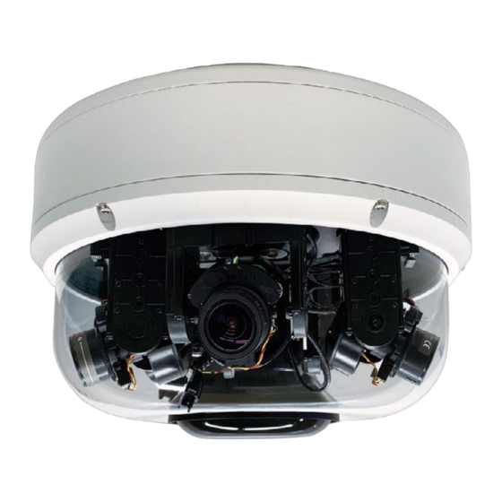
Introduction OVERVIEW The OE-C9912M20 is a 20MP outdoor, remotely PTZ repositionable, multisensor IP camera equipped with four, 5 Megapixel, 2.7~13.5mm VF, AF, Zoom lenses. Increase your return on investment with 360° coverage, equal to four single-sensor cameras, and simple installation through a single cable run. -
Page 10: Getting Started
Getting Started BOX CONTENTS Before proceeding, please confirm that the box contains the items listed here. Please contact your dealer for assistance if any item is missing or has defects. OE-C9912M20 Multisensor Mounting Accessory Kit Camera and Desiccant Rubber Grommets... -
Page 11: Camera Overview
CAMERA OVERVIEW CAMERA DIMENSIONS CONNECTIONS 24vDC + Power (12vDC) White GND - Audio Out + Audio I/O Black Audio Out - Audio In + Audio I/O Black Audio In - Alarm Out + Purple Alarm In - Alarm I/O Orange Alarm In + Black Alarm In -... -
Page 12: Connections (Cont.)
CONNECTIONS (CONT.) NOTE: An external power source is required for alarm in and alarm out. Alarm In 3.3V – 12V Max Alarm Out 30V Max... -
Page 13: Connections (Cont.)
CONNECTIONS (CONT.) RJ-45 For network and PoE connections Power (24vDC) Power Connection Alarm I/O Alarm Connection Audio In Audio In Audio Out Audio Out MicroSD Card Slots (2) Supports up to 512GB microSD card for Edge storage. Do not add or remove the microSD card when the camera is powered on. -
Page 14: Power Connection
For an adequate power connection, use a 12vDC or 24vAC adaptor. Alternatively, you can power the camera by PoE++ using the PoE power injector provided with the camera, or if a Power Sourcing Equipment (PSE) switch is available. Note OpenEye recommends against using more than one power source at a time. -
Page 15: Installation
INSTALLATION To prepare the camera for wall or ceiling installation with accessories, see instructions on Quick Installation Guide. 37959AA... -
Page 16: Network Camera Manager
Network Camera Manager OpenEye Network Camera Manager (NCM) is a software tool that allows you to quickly and easily connect and configure your OpenEye IP Cameras. This software allows you to apply the camera password, assign IP addresses, configure video settings, and update firmware on multiple cameras at once. -
Page 17: Username And Password
Username: admin The admin user password can be set using the following methods: OpenEye recorders running Apex 2.6 or newer will automatically set a new unique password when added in setup, if a new password has not already been set. -
Page 18: Live View
Live View The camera displays a live view using the MJPEG stream for setup purposes. Item Description Go to Setup to access the camera menus Display live views horizontally Display live views 2x2 Click to take a snapshot from the selected lens Refresh the page Switch to full-screen mode... -
Page 19: Power Modes
POWER MODES AT: The camera detects the power provided to the camera is equivalent to IEEE • 802.3at. With a maximum output of ~25W, this is sufficient to power all camera functions, excluding the IR LEDs. If the camera attempts to turn on the IR LEDs, the following message will be displayed in the live video for all sensors, “Insufficient power. -
Page 20: Setup
Setup STREAM SETTINGS VIDEO Primary Stream Codec - Configures the format of the video stream, the options are H.265 and H.264. Resolution - Configures the resolution of the video stream. Rate Control - Configures the Rate Control mode as CBR (constant bit rate) or VBR (variable bit rate) for the stream. -
Page 21: Secondary Stream
Smart GOP - Enables or disables Smart GOP feature. Enabling it will allow GOP to automatically increase when no moving objects are detected to save bandwidth. When moving objects are detected, GOP will automatically decrease. Bit Rate - Configures the bit rate, the range is 500~12000. Users can enter the value or adjust it through the slider bar. -
Page 22: Audio
AUDIO Audio Configuration Audio In - Enables or disables audio-in on the camera. The available options are ON and OFF. Audio In Volume - Volume adjustment for audio-in of the camera. The available options are High, Mid and Low. Audio Out - Enables or disables audio-out on the camera. The available options are ON and OFF. -
Page 23: Image
IMAGE EXPOSURE Exposure Global Mode - The available options are ON and OFF. ON - Set up the parameters for 4 image channels together. After enabling Global ON, please also select “Sync Brightness” from the AE Mode. Then, the parameters of all the 4 image channels will be the same and can be adjusted together. -
Page 24: Day/Night Settings
BLC (Backlight Compensation) - Enable this option if an image in the camera is too dark. WDR (Wide Dynamic Range) - Enable this function in scenes with high contrast lighting. The available options are OFF, Low, Medium and High. AWB Mode (Auto White Balance Mode) White balance allows the camera to produce more accurate colors under different lighting conditions. -
Page 25: Basic Settings
BASIC SETTINGS Flip left-to-right & Flip top-to-bottom Flips the image horizontally (flip left-to-right) or vertically (flip top-to-bottom). They can be selected separately. Digital Processing Sharpness Adjust - Configures the sharpness of the image, the range is 0 ~ 255, with 0 being the lowest sharpness. - Page 26 Hue Adjust - Configures the overall hue of the image, the range is 0 ~ 100. Increasing the value will adjust the image hue towards red. Decreasing the value will adjust the image hue towards blue. The default value is 50. Restore Settings to Defaults - Discards all the settings applied to the image and reset to the default settings.
-
Page 27: Ptz
PTZ Configuration Allows users to adjust the Focus/Pan/Tilt/Zoom/Auto Focus positions for each individual module or for all four modules. The available options are View1, View2, View3, View4 and All. Preset The available options for the preset buttons are 180 Wide, 180 Tele, 270 Wide, 270 Corner, 360, Re-Calibration, User Preset 1 and User Preset 2. -
Page 28: Roi
ROI Zones ROI is used to select which areas will be monitored and recorded with higher image quality while using lower image quality for other non-ROI zones to save bandwidth and storage. The instructions below illustrate how to setup ROI. Select Stream 1 or Stream 2 to set the ROI on. -
Page 29: Privacy Zone
PRIVACY ZONE Configures which area of the video stream will be masked for privacy. There are 5 privacy zones that can be configured. Select ON to enable Privacy Zone function. The default is OFF. Each channel can be edited individually. 2. -
Page 30: Osd
General Settings Camera Name - Specifies a name for the device. The maximum length is 32 characters. Background - Configures the background color of the text overlay, the options are Translucent (light gray) or Transparent. Text Color - Configures the text color as Black, White, Green or Yellow. Top Left/Top Right/Bottom Left/Bottom Right - There are 4 content positions (Top Left, Top Right, Bottom Left and Bottom Right) to display the camera name, current date/time and text overlay. -
Page 31: Network
NETWORK BASIC IPv4 Settings DHCP - Enables or disables DHCP, use this feature if the camera is connected to a network with DHCP server. To manually configure an IP address, disable DHCP and input the IP address, subnet mask, default gateway, primary and secondary DNS server address. System Settings HTTP Port - Configures the HTTP port number of the web configuration menu. -
Page 32: Ftp
FTP Configuration Enable - Enables or disables FTP access to this camera. This function is only available when an SD card is inserted. You can access files in the SD card attached to the IP camera. Password - Specifies the FTP login password to access the IP camera. Max Connection - Specifies the maximum number of FTP connections the IP camera can support. -
Page 33: Snmp
SNMP SNMP Configuration No SNMP Server - Disables SNMP function. SNMP V2c - Enables or disables SNMPv2c support. Community String - Configures the community string. Trap Configuration - Specifies the destination IP address to send SNMP trap messages. SNMP V3 - Enables or disables SNMPv3 support. User - Configures the SNMPv3 username. - Page 34 Privacy - Configures encryption for SNMPv3. The options are DES and AES. Trap Configuration - Specifies the destination IP address to send SNMP trap messages. Download MIB - Download MIB file for SNMP Save - Save configurations. Reset - Reset button to discard all the settings and revert to the previous settings.
-
Page 35: Firewall
FIREWALL Firewall Configuration Mode - Select OFF to disable the filtering of the specified IP address. Select Allow or Deny in the drop-down menu to specify the type of filtering rule applied to the IP address entered. Address1 to Address8 - The IP address and associated protocol (TCP, UDP or None) to filter can be entered here. -
Page 36: Ddns
DDNS DDNS Configuration Enable - Enables or disables DDNS service. Hostname - Hostname of the DDNS account. DDNS Server - Select the DDNS service provider from the drop-down menu, the available providers are DynDNS, NO-IP, and Two-DNS. The default option is DynDNS. User Name –... -
Page 37: Rtsp
RTSP RTSP Configuration Authentication - Enables or disables verification of the account and password. Port - Configures the port number for stream 1 to stream 3. The range is 554/1025~65535. Stream 1 to Stream 3 - Enables or disables RTSP unicast for stream 1 to stream 3. The RTSP port number and pathname for each stream can be configured here. -
Page 38: Multicast
Multicast Enable RTSP Multicast - Enables or disables RTSP multicast streaming. Always Multicast - Check this option to enable the video stream to start multicast streaming without using RTCP. Video IP - Configures the multicast address to stream video. Video Port - Configures the port number of the video stream. Audio IP - Configures the multicast address to stream audio. -
Page 39: System
SYSTEM DATE / TIME Display Format Setting Display Format - Displays the current date and time. There are various formats to select from the drop-down menu. Date & Time Format - Select the display format of the date and time. The available options are 24HR and 12HR. -
Page 40: Maintenance
MAINTENANCE System Information Firmware Version & Model Name - Displays the current firmware version and IP camera model number. Serial Number & MAC Address - Displays the IP camera serial number and MAC address. Firmware Update - To update the camera’s firmware, click on the Choose a file button and locate the firmware image file, once the file is selected, press the Upload button to begin. -
Page 41: Backup
CAUTION: During update, please do not disconnect the network cable, reset or power off the IP camera, as you may damage the device. Reboot Camera - Click this button to reboot the camera. Reset to Default - Click this button to restore all the camera’s setting back to factory default except IP address (keeps all the settings on the Network Basic setting page). -
Page 42: User Management
USER MANAGEMENT Admin Setting Admin - The default username is admin. Users cannot change it. Password - Set up the password for administrator’s authorization. Re-type Password - Retype the same password to confirm. User List Displays user accounts available on the camera. Press Add New User to add a new account and set up the authorization level of this user under User Information. -
Page 43: Event
EVENT ALARM HANDLER Alarm Handler Configurations Enable - Enables or disables the alarm schedule setup. Alarm Schedule Settings S - Press S for a particular weekday to set up a 24-hour schedule automatically. D - Press D for a particular weekday to clear all the previous scheduled settings automatically. - Page 44 Configure the scheduled time by holding down the mouse button and clicking the time block to enable the schedule settings on the selected time. A light blue color on the time block indicates that the alarm schedule is enabled, while a light gray color indicates that the alarm schedule is disabled.
-
Page 45: Motion Detection
MOTION DETECTION Motion Configurations This section configures which area of the live video will be monitored for detecting motion. Enable - Enables or disables motion detection function. Sensitivity - Configures the sensitivity of motion detection, the range is 0 to 100. Zone1 to Zone5 Setup: Configures the type of area layout to use for motion detection. -
Page 46: Alarm Schedule Settings
Alarm Schedule Settings S - Press S for a particular weekday to set up a 24-hour schedule automatically. D - Press D for a particular weekday to clear all the previous scheduled settings automatically. Configure the scheduled time by holding down the mouse button and clicking the time block to enable the schedule settings on the selected time. -
Page 47: Tampering Alarm
TAMPERING ALARM Tampering Alarm Configurations Enable - Enables or disables the tampering alarm function. Tampering Sensitivity - Configures the sensitivity level of tampering alarm, the options are High, Medium and Low. 37959AA... -
Page 48: Alarm Schedule Settings
Alarm Schedule Settings S - Press S for a particular weekday to set up a 24-hour schedule automatically. D - Press D for a particular weekday to clear all the previous scheduled settings automatically. Configure the scheduled time by holding down the mouse button and clicking the time block to enable the schedule settings on the selected time. -
Page 49: Ftp Upload
FTP UPLOAD FTP Upload Handler Configurations Configures which type of event trigger to enable and the FTP server address that the camera will connect to. The options are: Trigger Alarm Detection • Trigger Motion Detection • Trigger Tampering Alarm • Trigger Scheduled •... - Page 50 Pre-event Snapshot Interval - Configures the interval of pre-event snapshots. The options are 1, 3, 5 and 10. Post-event Snapshot Interval - Configures the interval of post-event snapshots. The options are 1, 3, 5 and 10. FileName Prefix - Configures a prefix to append to the filename. The default prefixes for Alarm, Motion, Tampering Detection and Video Analysis are Alarm, Motion, and Tampering respectively.
-
Page 51: Smtp Notification
SMTP NOTIFICATION SMTP Notification Configurations This section configures the SMTP mail server address that the camera will use for sending emails. From - Specifies the email address of the sender. Snapshot Send Mode - Choose between Send all camera image or Send trigger camera image. -
Page 52: Recipient List
Password - Specifies the login password for the SMTP mail server. Authentication Mode - Specifies the SMTP server authentication mode, the options are NO_AUTH, SMTP_PLAIN, LOGIN and TLS_TLS. Recipient List Specifies the email address to send the email when an event is triggered by Alarm, Motion, or Tampering. -
Page 53: Network Storage
NETWORK STORAGE Network Storage Configurations Network Storage - This section configures the network storage server address that the camera will use when an event trigger is detected. Trigger Event - Configures which type of event trigger to enable and the network storage server that the camera will connect to. - Page 54 Save - Save configurations. Reset - Reset button to discard all the settings and revert to the previous settings.
-
Page 55: Relay Handler
RELAY HANDLER Relay Handler Configurations This section configures the event trigger options for devices connected to the DI/DO of the camera. Trigger Alarm Detection - When a signal is detected from Alarm in, the Alarm out will be triggered. Trigger Motion Detection - When a motion detection event is detected, the Alarm out will be triggered. -
Page 56: Sd Record
SD RECORD SD Record Handler Configures which type of event trigger to enable the SD recording and scheduling function. The following options are available: Enable Trigger Alarm Detection • Enable Trigger Motion Detection • Enable Trigger Tampering Alarm • Enable Trigger Scheduled •... -
Page 57: Motion Detection Settings
Record Type - Configures the recording method to record the stream on to the SD card. The options are Video or Snapshot. Save - Save configurations. Reset - Reset button to discard all the settings and revert to the previous settings. Motion Detection Settings Pre-Event Record - Configures the length of the pre-event recording. -
Page 58: Tcp Notify
TCP NOTIFY... - Page 59 View - Assign a View number (1-4) for the configured TCP/IP detection types. Trigger Motion Detection - Configure IP Address and Port destinations, and message for a Trigger Motion Detection. Trigger Zone Motion Detection - Configure IP Address and Port destinations, and message for Trigger Zone Motion Detection (1-5).
- Page 60 © 2023 OpenEye All rights reserved. No part of this publication may be reproduced by any means without written permission from OpenEye. The information in this publication is believed to be accurate in all respects. However, OpenEye cannot assume responsibility for any consequences resulting from the use thereof.
Need help?
Do you have a question about the OE-C9912M20 and is the answer not in the manual?
Questions and answers