
Related Manuals for Arestech MERA-2000 Series


Summary of Contents for Arestech MERA-2000 Series
- Page 1 User Manual MERA-2000 Series Modular Embedded Computers with Intel® Celeron® J1900 Processor...
- Page 2 User Manual Record of Revisions Version Issue Date Descriptions Made By 2021/09/27 First Release Jerry...
- Page 3 Product Warranty (2 Years) Arestech warrants to you, the original purchaser, that each of its products will be free from defects in materials and workmanship for two years from the invoice date. This warranty does not apply to any products which have been repaired or altered by persons other than repair personnel authorized by Arestech, or which have been subject to misuse, abuse, accident, or improper installation.
- Page 4 User Manual Safety Instructions Read these safety instructions carefully. Keep this User Manual for later reference. Disconnect this equipment from any AC outlet before cleaning. Use a damp cloth. Do not use liquid or spray detergents for cleaning. For plug-in equipment, the power outlet socket must be located near the equipment and must be easily accessible.
- Page 5 User Manual Safety Precaution - Static Electricity Follow these simple precautions to protect yourself from harm and the products from damage: 1. To avoid electrical shock, always disconnect the power from your PC chassis before you work on it. Don't touch any components on the CPU card or other cards while the PC is on. 2.
-
Page 6: Table Of Contents
User Manual Contents Chapter 1. Product Introductions .................. 8 1.1 Overview ........................8 1.2 Hardware Specifications ..................9 1.2.1 MERA-2000-2L Specification ................ 9 1.2.2 MERA-2001(S)-2L Series Specification............10 1.3 Panel I/O ........................ 11 1.3.1 Front Panel....................11 1.3.2 Rear Panel ....................13 1.3.3 Right Panel .................... - Page 7 User Manual 3.9 Installing The DIN-Rail Holder ................46 Chapter 4. BIOS Setup ....................47 4.1 BIOS Introduction ....................47 4.2 Main Setup ......................48 4.3 Advanced Setup ..................... 49 4.3.1 Trusted Computing (Optional) ..............49 4.3.2 ACPI Settings ....................50 4.3.3 Super IO Configuration ................
-
Page 8: Chapter 1. Product Introductions
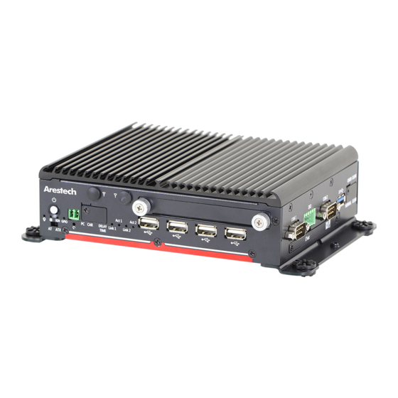
Chapter 1. Product Introductions 1.1 Overview MERA-2000 series is a compact fanless system with Intel® Celeron® J1900 quad-core processor. The system integrates rich I/O and supports vehicle power ignition function. It has a wide-range DC power input from 9V to 48V, wide operating temperature range of -40°C to +70°C, and an industrial- grade protection (RVP, OVP, OCP, ESD, surge, etc.). -
Page 9: Hardware Specifications
User Manual 1.2 Hardware Specifications 1.2.1 MERA-2000-2L Specification... -
Page 10: Mera-2001(S)-2L Series Specification
User Manual 1.2.2 MERA-2001(S)-2L Series Specification... -
Page 11: Panel I/O
User Manual 1.3 Panel I/O 1.3.1 Front Panel ◼ ◼ Power On/Off Button Removable HDD Port Press to turn on or off the system Removable 2.5" SATA HDD area ◼ ◼ AT/ATX Mode Select Switch Power LED Used to select AT or ATX power mode Indicates the power status of the system ◼... - Page 12 User Manual MERA-2001(S)-2L...
-
Page 13: Rear Panel
User Manual 1.3.2 Rear Panel ◼ ◼ Line Out DC In Used to connect a speaker Used to plug in a DC power input with terminal block ◼ Mic In ◼ Used to connect a microphone Earthing Screw Hole Used to connect the ground wire ◼... - Page 14 User Manual MERA-2001S-2L...
-
Page 15: Right Panel
User Manual 1.3.3 Right Panel ◼ ◼ COM Port Clear CMOS COM1 ~ COM2 support RS232/422/485 Used to clear CMOS serial device ◼ ◼ Digital I/O Terminal Block CFast Socket Supports 4 digital inputs and 4 digital Used to insert a CFast card outputs ◼... -
Page 16: Mechanical Dimensions
User Manual 1.4 Mechanical Dimensions 1.4.1 MERA-2000-2L... -
Page 17: Mera-2001(S)-2L
User Manual 1.4.1 MERA-2001(S)-2L... -
Page 18: Chapter 2. Switches And Connectors
User Manual Chapter 2. Switches and Connectors 2.1 Switches and Connectors 2.1.1 Front View 2.1.2 Rear View... -
Page 19: Right View
User Manual 2.1.3 Right View... -
Page 20: Switches, Leds And Connectors Definitions
User Manual 2.2 Switches, LEDs and Connectors Definitions ◼ List of Switches and LEDs Location Definition PWR_SW1 Power Button AT_ATX1 AT / ATX Power Mode Switch RESET1 Reset Button CLR_CMOS1 Clear BIOS Switch PC_CAR1 PC / Car Mode Switch DELAY_TIME1 Car mode system turn off delay time PWR_LED1 Power LED Status... - Page 21 User Manual ◼ List of Connectors Location Definition PWR_SW2 Remote Power On/Off Connector USB1_1 USB 3.0 Port USB2_1, USB3_1, USB4_1,USB5_1 USB 2.0 Port COM1_1, COM2_1, COM3_1, RS232 / RS422 / RS485 Connector COM4_1, COM5_1, COM6_1 CFAST1 CFast Socket 3-pin DC 9~48V Power Input with Power Ignition DC_IN1 Connector SIM1, SIM2...
-
Page 22: Switch Definitions
User Manual 2.3 Switch Definitions ◼ PWR_SW1: Power Button Switch Definition Push Power On/Off System ◼ AT_ATX1: AT / ATX Power Mode Switch Definition 1-2 (Right) ATX Power Mode (Default) 2-3 (Left) AT Power Mode ◼ RESET1: Reset Button Switch Definition Push Reset System... - Page 23 User Manual ◼ DELAY_TIME1: Switch to Car Mode to Turn off Delay Time Switch Definition 1 / 2 / 3 ON / ON / ON Shutdown Timer by O.S (Default) ON / ON / OFF 1 min. ON / OFF / ON 5 mins.
- Page 24 User Manual Step 3: Connect the vehicle battery and ignition signal ◼ PWR_LED1: Power Status LED Power Status LED Color Power ON Blue ◼ HDD_LED1:HDD Status LED HDD Status LED Color HDD Read/Write Yellow ◼ IGN_LED1:Ignition Status LED IGN Status LED Color IGN ON Green...
-
Page 25: Connector Definitions
User Manual 2.4 Connector Definitions ◼ PWR_SW2:Remote Power Switch Connector Type:Terminal Block 1X2 2-pin, 3.5mm pitch Definition Power Button ◼ COM1_1, COM2_1, COM3_1, COM4_1, COM5_1, COM6_1:RS232 / RS422 / RS485 Connector Connector Type:9-pin D-Sub RS232 RS422 / 485 Full RS485 Half Duplex Definition Duplex Definition Definition... - Page 26 User Manual Active LED Staus Definition Blinking Yellow Data Activity No Activity ◼ DIO1_1:Digital Input / Output Connector Connector Type:Terminal Block 2X5 18-pin, 3.5mm pitch Definition Definition External DC Voltage Input External GND...
- Page 27 User Manual ◼ POWER1:Power Connector Connector Type:1X4-pin Wafer, 2.0mm pitch Definition +12V ◼ MINIPCIE1:Mini PCI-Express Socket (Support SIM Card to Link feature) Definition Pin Definition WAKE# +3.3Vaux +1.5V CLKREQ2# UIM1_PWR USIM1_DATA PCIE_CLK- USIM1_CLK PCIE_CLK+ USIM1_RST USIM1_VPP RESERVED RESERVED W_DISABLE# RESET# PCIE_RXN2 +3.3Vaux PCIE_RXP2...
- Page 28 SOME OFF-THE-SHELF MINI-PCIE MODULES ARE NOT COMPATIBLE WITH THE +3.3VAUX POWER AND ARE ONLY COMPATIBLE WITH THE +3.3V POWER DESIGN. IF ANY SIMILAR SITUATION ARISES, PLEASE CONTACT ARESTECH FOR SOLUTIONS. ◼ CN1:Dual Mode Mini PCI-Express (Support mSATA and SIM Card to Link feature)
-
Page 29: Chapter 3. System Setup
User Manual Chapter 3. System Setup WARNING: TO PREVENT ELECTRIC SHOCK OR SYSTEM DAMAGE, PLEASE MUST TURN OFF THE POWER AND DISCONNECT THE DEVICE FROM THE POWER SOURCE BEFORE REMOVING THE TOP OR BOTTOM CHASSIS COVER. 3.1 Installing A SODIMM ◼... - Page 30 User Manual 3. Locate the SODIMM socket. 4. Insert the SODIMM module at 45-degree angle 5. Press the module down until it’s fixed firmly by the two locking latches.
- Page 31 User Manual ◼ MERA-2001(S)-2L 1. Turn over the system to have the bottom side face up and loosen the 6 screws at the bottom. 2. Remove the bottom cover. 3. Remove the hard drive bay on the side.
- Page 32 User Manual 4. Locate the SODIMM socket. 5. Insert the SODIMM module at 45-degree angle. 6. Press the module down until it’s fixed firmly by the two locking latches.
-
Page 33: Replacing A Cmos Battery
User Manual 3.2 Replacing A CMOS Battery ◼ MERA-2000-2L 1. Turn over the system to have the bottom side face up and loosen the 2 screws at the bottom. 2. Remove the bottom cover. 3. Locate the CMOS Battery. - Page 34 User Manual 4. Remove the old CMOS battery. 5. Install a new CMOS battery in the battery holder. ◼ MERA-2001(S)-2L 1. Turn over the system to have the bottom side face up and loosen the 6 screws at the bottom.
- Page 35 User Manual 2. Remove the bottom cover. 3. Remove the hard drive bay on the side. 4. Locate the CMOS Battery.
- Page 36 User Manual 5. Remove the old CMOS battery. 6. Install a new CMOS battery in the battery holder.
-
Page 37: Installing A Mini-Pcie / Msata Module
User Manual 3.3 Installing A mini-PCIe / mSATA Module 1. Turn the SATA HDD thumb screw on the front panel and remove the SATA HDD bay. 2. Turn over the system to have the top side face up and loosen the six screws on the left and right sides. - Page 38 User Manual 4. Loosen the 3 screws and remove the HDD tray. 5. Locate the mini-PCIe sockets. Please note that the left connector (CN1) is shared by mini- PCIe/mSATA interface, and right connector (MINIPCIE1) is mini-PCIe interface. Both support SIM card to Link feature.
- Page 39 User Manual 7. Press the mini-PCIe/mSATA module down and lock it with two screws. 8. If you have a half-size mini-PCIe card, make sure use extender to make it full-size as shown below.
-
Page 40: Installing An Antenna
User Manual 3.4 Installing An Antenna 1. Remove the antenna hole covers at front or rear panel. Front Rear 2. Have the antenna jack penetrate through the hole. 3. Put on the washer and fasten the nut with the antenna jack. 4. - Page 41 User Manual 5. Attach the RF connector at the cable-end onto the mini-PCIe Wi-Fi module.
-
Page 42: Installing A Sim Card Or Cfast Card
User Manual 3.5 Installing A SIM Card or CFast Card 1. Loosen the 2 screws on the right panel to remove the CFast / SIM cover plate. 2. Insert the CFast / SIM card into the socket. ◎ NOTE: 1. PLEASE NOTE THAT THE INSTALLATION OF SIM1_1 and SIM2_1 HAS TO MATCH THE INSTALLATION OF MINI-PCIE SOCKET. -
Page 43: Installing The Front Removable Sata Hdd Bay
User Manual 3.6 Installing The Front Removable SATA HDD Bay 1. Unscrew the two thumb screws circled below to take out the removable 2.5” SATA HDD bay. 2. Lock the 2.5” SATA HDD with HDD bracket using four screws. 3. Slide the HDD bracket back and then fasten the thumb screws. -
Page 44: Installing The Right Removable Sata Hdd Bay (Mera-2001(S)-2L Only)
User Manual 3.7 Installing The Right Removable SATA HDD Bay (MERA- 2001(S)-2L Only) 1. Unscrew the two thumb screws circled below to take out the removable 2.5” SATA HDD bay. 2. Lock the 2.5” SATA HDD with HDD bracket using four screws. 3. -
Page 45: Installing The Wall Mount Brackets
User Manual 3.8 Installing The Wall Mount Brackets 1. Wall mount kit is included in the standard package. 2. The mounting holes are at the bottom of system. 3. Use the provided 4 screws to fasten the bracket with each side of system. -
Page 46: Installing The Din-Rail Holder
User Manual 3.9 Installing The DIN-Rail Holder 1. The DIN-Rail bracket is an optional accessory. 2. Place the system upside down so you can see the bottom cover with two screw holes for the DIN-Rail holder. 3. Place the DIN-Rail holder on the top of the bottom cover and lock it with two screws. -
Page 47: Chapter 4. Bios Setup
User Manual Chapter 4. BIOS Setup 4.1 BIOS Introduction The system BIOS software is stored on EEPROM. The BIOS provides an interface to modify the configuration. When the battery is removed, all the parameters will be reset. ◼ BIOS Setup Power on the embedded system and by pressing <Del>... -
Page 48: Main Setup
User Manual 4.2 Main Setup Press <Del> to enter BIOS CMOS Setup Utility. The Main setup screen is showed as follows when the setup utility is entered. System Date/Time is set up in the Main Menu. ◼ System Date To set the system date, please use <Tab> to switch between data elements. ◼... -
Page 49: Advanced Setup
User Manual 4.3 Advanced Setup 4.3.1 Trusted Computing (Optional) ◼ Security Device Support Enable or disable TPM function... -
Page 50: Acpi Settings
User Manual 4.3.2 ACPI Settings ◼ Enable ACPI Auto Configuration This item allows you to enable or disable BIOS ACPI Auto Configuration. ◼ Enable Hibernation This item allows you to enable or disable system ability to hibernate. ◼ ACPI Sleep State This item selects the highest ACPI sleep state the system will enter when the suspend button is pressed. -
Page 51: Super Io Configuration
User Manual 4.3.3 Super IO Configuration This setting allows you to select options for the Super IO Configuration and change the value of the selected option. ◼ Serial Port 1 Configuration... - Page 52 User Manual ◼ Serial Port 2 Configuration ◼ Serial Port 3 Configuration...
- Page 53 User Manual ◼ Serial Port 4 Configuration ◼ Serial Port 5 Configuration...
- Page 54 User Manual ◼ Serial Port 6 Configuration ◼ Serial Port This item allows you to enable or disable serial port. ◼ Change Settings This item allows you to change the address & IRQ settings of the specified serial port. ◼ Device Type Select To change the Serial interface, please select <RS232>, <RS422 Full Duplex>...
-
Page 55: Hardware Monitor
User Manual 4.3.4 Hardware Monitor These items display the current status of all monitored hardware devices / components such as voltages and temperatures. -
Page 56: Serial Port Console Redirection
User Manual 4.3.5 Serial Port Console Redirection ◼ Console Redirection These items allows you to enable or disable COM1~COM6 console redirection. ◼ Legacy Console Redirection Settings Select a COM port to display redirection of Legacy OS and Legacy OPROM Messages. ◼... -
Page 57: Cpu Configuration
User Manual 4.3.6 CPU Configuration ◼ Intel Virtualization Technology Virtualization enhanced by Intel Virtualization Technology will allow a platform to run multiple operating systems and applications in independent partitions. With virtualization, one computer system can function as multiple Virtual systems. -
Page 58: Ppm Configuration
User Manual 4.3.7 PPM Configuration ◼ CPU C state Report This item allows you to enable or disable CPU C state report to OS.. ◼ Max CPU C- State This option controls Max C state that the processor will support. ◼... -
Page 59: Sata Configuration
User Manual 4.3.8 SATA Configuration ◼ SATA Speed Support Change the SATA Speed. Select <Gen1> or <Gen2> speed. ◼ SATA Mode This item allows you to select IDE or AHCI Mode. ◼ SATA Port 0 This item allows you to enable or disable SATA Port 0. ◼... -
Page 60: Os Selection
User Manual 4.3.9 OS Selection ◼ OS Selection This item allows you to to select Windows 7 or Windows 8.X/10.X OS. -
Page 61: Network Stack Configuration
User Manual 4.3.10 Network Stack Configuration ◼ Network Stack Use this item to enable or disable UEFI Network Stack. -
Page 62: Csm Configuration
User Manual 4.3.11 CSM Configuration ◼ CSM Support Enables or disables UEFI CSM (Compatibility Support Module) to support a legacy PC boot process. ◼ Boot Option Filter This item allows you to select which type of operating system to boot. UEFI and Legacy: Allows booting from operating systems that support legacy option ROM or UEFI option ROM. - Page 63 User Manual ◼ Video Controls the execution of UEFI and Legacy Video OpROM Do not launch: Disables option ROM. UEFI only: Enables UEFI option ROM only. Legacy only: Enables legacy option ROM only.
-
Page 64: Usb Configuration
User Manual 4.3.12 USB Configuration ◼ Legacy USB Support Allows USB keyboard / mouse to be used in MS-DOS. ◼ XHCI Hand-off Determines whether to enable XHCI (USB3.0) Hand-off feature for an operating system without XHCI (USB3.0) Hand-off support. ◼ EHCI Hand-off Determines whether to enable EHCI Hand-off feature for an operating system without EHCI Hand-off support. -
Page 65: Chipset
User Manual 4.4 Chipset... -
Page 66: North Bridge
User Manual 4.4.1 North Bridge This section provides information on the installed memory size and memory/onboard graphics- related configuration options. ◼ IGD Configuration This section provides onboard graphics-related configuration options. ◼ IGD Turbo Enable This item allows you to enable or disable IGD Turbo. - Page 67 User Manual ◼ PAVC This item enables/disables Protected Audio Video Control. Select <Disabled>, <LITE Mode> or <SERPENT Mode>. ◼ DVMT Pre-Allocated This item selects DVMT 5.0 Pre-Allocated (Fixed) Graphics Memory size used by the Internal Graphics Device. Select <64M>, <96M>, <128M>, <160M>, <192M>, <224M>, <256M>, <288M>, <320M>, <352M>, <384M>, <416M>, <448M>, <480M>...
-
Page 68: South Bridge
User Manual 4.4.2 South Bridge ◼ Azalia HD Audio Control detection of the Azalia device. Audio Controller Enabled: Azalia will be unconditionally enabled. Disabled: Azalia will be unconditionally disabled. ◼ USB Configuration... - Page 69 User Manual ◼ XHCI Mode This item allows you to enable or disable the USB XHCI controller. ◼ USB 2.0 (EHCI) Support This item allows you to enable or disable the USB EHCI support. ◼ PCI Express Configuration Control detection of the Azalia device. ◼...
-
Page 70: Security
User Manual 4.5 Security Security menu allows you to change administrator password and user password settings. ◼ Administrator Password This item allows you to set Administrator Password. ◼ User Password This item allows you to set User Password. -
Page 71: Boot
User Manual 4.6 Boot This menu allows you to setup the system boot options. ◼ Setup Prompt Timeout This item sets number of seconds to wait for setup activation key. ◼ Bootup NumLock State This item selects the keyboard NumLock state. Select <On> or <Off>. ◼... -
Page 72: Save & Exit
User Manual 4.7 Save & Exit This setting allows you to configure the boot settings. ◼ Save Changes and Reset This item allows you reset the system after saving the changes. ◼ Discard Changes and Reset Select this option to quit Setup without making any permanent changes to the system configuration.
Need help?
Do you have a question about the MERA-2000 Series and is the answer not in the manual?
Questions and answers