
Related Manuals for Arestech MEGA 3110 Series


Summary of Contents for Arestech MEGA 3110 Series
- Page 1 User Manual MEGA-3110 Series High-Performance GPU Computer with Intel® 9th / 8th LGA1151 Processors...
- Page 2 User Manual Record of Revisions Version Issue Date Descriptions Made By 2021/10/18 First Release Jerry...
- Page 3 Product Warranty (2 Years) Arestech warrants to you, the original purchaser, that each of its products will be free from defects in materials and workmanship for two years from the invoice date. This warranty does not apply to any products which have been repaired or altered by persons other than repair personnel authorized by Arestech, or which have been subject to misuse, abuse, accident, or improper installation.
- Page 4 User Manual Safety Instructions Read these safety instructions carefully. Keep this User Manual for later reference. Disconnect this equipment from any AC outlet before cleaning. Use a damp cloth. Do not use liquid or spray detergents for cleaning. For plug-in equipment, the power outlet socket must be located near the equipment and must be easily accessible.
- Page 5 User Manual Safety Precaution - Static Electricity Follow these simple precautions to protect yourself from harm and the products from damage: 1. To avoid electrical shock, always disconnect the power from your PC chassis before you work on it. Don't touch any components on the CPU card or other cards while the PC is on. 2.
-
Page 6: Table Of Contents
User Manual Contents Chapter 1. Product Introductions .................. 8 1.1 Overview ........................8 1.2 MEGA-3110 Series Specifications ................9 1.3 Panel I/O ........................ 11 1.3.1 Front Panel....................11 1.3.2 Top Panel ....................13 1.4 Mechanical Dimensions ..................15 1.4.1 MEGA-3112 ....................15 1.4.2 MEGA-3113 .................... - Page 7 User Manual 3.13 Connecting The Expansion Module with The PC Module ......55 3.14 Installing A Stand / Wall Mount ..............56 Chapter 4. BIOS Setup ....................57 4.1 BIOS Introduction ....................57 4.2 Main Setup ......................58 4.3 Advanced Setup ..................... 59 4.3.1 CPU Configuration ..................
-
Page 8: Chapter 1. Product Introductions
User Manual Chapter 1. Product Introductions 1.1 Overview MEGA-3110 series is a high-spec GPU system equipped with convertible expansion module technology (CEM technology). It supports PCIe modular expansion functions and can be used with nVIDIA RTX-2080 or higher GPU graphics cards or accelerator cards. It can reduce CPU loading and increase the speed and ability of image processing. -
Page 9: Mega-3110 Series Specifications
User Manual 1.2 MEGA-3110 Series Specifications... - Page 10 User Manual...
-
Page 11: Panel I/O
User Manual 1.3 Panel I/O 1.3.1 Front Panel ◼ ◼ Power On/Off Button Remote Power On/Off Terminal Block Press to turn on or off the system Used to plug in a remote power on/off terminal block ◼ AT/ATX Mode Select Switch ◼... - Page 12 User Manual MEGA-3112 MEGA-3113...
-
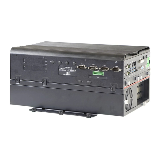
Page 13: Top Panel
User Manual 1.3.2 Top Panel ◼ ◼ Clear CMOS COM Port Used to clear CMOS COM1 ~ COM2 support RS232/422/485 serial device ◼ PC/Car Mode Select Switch ◼ Used to select PC or Car mode Digital I/O Terminal Block Supports 8 digital inputs and 8 digital ◼... - Page 14 User Manual MEGA-3113...
-
Page 15: Mechanical Dimensions
User Manual 1.4 Mechanical Dimensions 1.4.1 MEGA-3112... -
Page 16: Mega-3113
User Manual 1.4.2 MEGA-3113... - Page 17 User Manual...
-
Page 18: Chapter 2. Switches And Connectors
User Manual Chapter 2. Switches and Connectors 2.1 Switches and Connectors 2.1.1 Front View 2.1.2 Top View... -
Page 19: Switches, Leds And Connectors Definitions
User Manual 2.2 Switches, LEDs and Connectors Definitions ◼ List of Switches and LEDs Location Definition PWR_SW2 Power Button AT_ATX2 AT / ATX Power Mode Switch RESET2 Reset Button CLR_CMOS1 Clear BIOS Switch CAR_PWR1 PC / Car Mode Switch DELAY_TIME1 Car mode system turn off delay time PWR_LED2 Power LED Status... -
Page 20: Switch Definitions
User Manual 2.3 Switch Definitions ◼ PWR_SW2: Power Button Switch Definition Push Power On/Off System AT_ATX2: AT / ATX Power Mode Switch ◼ Definition 1-2 (Right) ATX Power Mode (Default) 2-3 (Left) AT Power Mode ◼ RESET2: Reset Button Switch Definition Push Reset System... - Page 21 User Manual ◼ DELAY_TIME1: Switch to Car Mode to Turn off Delay Time Switch Definition 1 / 2 / 3 ON / ON / ON Shutdown Timer by O.S (Default) ON / ON / OFF 1 min. ON / OFF / ON 5 mins.
- Page 22 User Manual Step 3: Connect the vehicle battery and ignition signal ◼ PWR_LED2: Power Status LED Power Status LED Color Power ON Blue ◼ IGN_LED2:Ignition Status LED IGN Status LED Color IGN ON Green ◼ GPIO_LED4:GPIO Status LED GPIO Status LED Color GPIO ON ◼...
-
Page 23: Connector Definitions
User Manual 2.4 Connector Definitions ◼ PWR_SW3:Remote Power Switch Connector Type:Terminal Block 1X2 2-pin, 3.5mm pitch Definition Power Button ◼ COM1_2_1:RS232 / RS422 / RS485 Connector Connector Type:9-pin D-Sub RS232 RS422 / 485 Full RS485 Half Duplex Definition Duplex Definition Definition DCD1 TX1-... - Page 24 User Manual ◼ COM3_1:RS232 / RS422 / RS485 Connector Connector Type:9-pin D-Sub RS232 RS422 / 485 Full RS485 Half Duplex Definition Duplex Definition Definition DCD3 TX3- DATA3- RxD3 TX3+ DATA3+ TxD3 RX3+ RX3- DSR3 RTS3 CTS3 ◼ COM4_1:RS232 / RS422 / RS485 Connector Connector Type:9-pin D-Sub RS232 RS422 / 485 Full...
- Page 25 User Manual ◼ COM5_1:RS232 / RS422 / RS485 Connector Connector Type:9-pin D-Sub RS232 RS422 / 485 Full RS485 Half Duplex Definition Duplex Definition Definition DCD5 TX5- DATA5- RxD5 TX5+ DATA5+ TxD5 RX5+ RX5- DSR5 RTS5 CTS5 ◼ COM6_1:RS232 / RS422 / RS485 Connector Connector Type:9-pin D-Sub RS232 RS422 / 485 Full...
- Page 26 User Manual ◼ DC_IN2:DC Power Input Connector (+24~48V) Connector Type: Terminal Block 2X3 3-pin, 5.0mm pitch Definition +24~48VIN +24~48VIN Power Ignition Power Ignition ◼ POWER1, POWER2:Power Connector Connector Type:1X4-pin Wafer, 2.0mm pitch Definition +12V ◼ DIO1_1:Digital Input / Output Connector Connector Type:Terminal Block 2X5 18-pin, 3.5mm pitch Definition Definition...
- Page 27 User Manual ◼ CN1, CN2, CN3:LAN and USB3.0 Port Connector Type: RJ45 port with LEDs and dual USB3.0 ports Definition Definition Definition LAN1_MDI0P USB2_D1- USB2_D2- LAN1_MDI0N USB2_D1+ USB2_D2+ LAN1_MDI1P LAN1_MDI2P USB3_RX1- USB3_RX2- LAN1_MDI2N USB3_RX1+ USB3_RX2+ LAN1_MDI1N LAN1_MDI3P USB3_TX1- USB3_TX2- LAN1_MDI3N USB3_TX1+ USB3_TX2+ Definition...
- Page 28 User Manual Definition Definition Definition LAN3_MDI0P USB2_D5- USB2_D6- LAN3_MDI0N USB2_D5+ USB2_D6+ LAN3_MDI1P LAN3_MDI2P USB3_RX5- USB3_RX6- LAN3_MDI2N USB3_RX5+ USB3_RX6+ LAN3_MDI1N LAN3_MDI3P USB3_TX5- USB3_TX6- LAN3_MDI3N USB3_TX5+ USB3_TX6+ Link LED Status Definition Steady Green 1Gbps Network Link Steady Orange 100Mbps Network Link 10Mbps Network Link Active LED Status Definition Blinking Yellow...
- Page 29 SOME OFF-THE-SHELF MINI-PCIE MODULES ARE NOT COMPATIBLE WITH +3.3VAUX POWER AND ARE ONLY COMPATIBLE WITH +3.3V POWER DESIGN. IF A SIMILAR SITUATION ARISES, PLEASE CONTACT ARESTECH FOR SOLUTIONS. ◼ MINIPCIE2:Mini PCI-Express Socket (Support mPCIe, USB2.0 and SIM Card to Link Feature)
- Page 30 SOME OFF-THE-SHELF MINI-PCIE MODULES ARE NOT COMPATIBLE WITH +3.3VAUX POWER AND ARE ONLY COMPATIBLE WITH +3.3V POWER DESIGN. IF A SIMILAR SITUATION ARISES, PLEASE CONTACT ARESTECH FOR SOLUTIONS. ◼ CN4:Dual Mode Mini PCI-Express (Support mPCIe, mSATA, USB2.0 and SIM Card to Link...
- Page 31 User Manual +1.5V +3.3Vaux ◼ CN5:Dual Mode Mini PCI-Express (Support mPCIe, mSATA, USB2.0 and SIM Card to Link Feature) Pin Definition Definition WAKE# +3.3Vaux +1.5V CLKREQ10# USIM4_PWR USIM4_DATA PCIE_CLK10- USIM4_CLK PCIE_CLK10+ USIM4_RST USIM4_VPP RESERVED RESERVED W_DISABLE# RESET# PCIE_RXN18 (SATA_RXP5) +3.3Vaux PCIE_RXP18 (SATA_RXN5) +1.5V SMB_CLK...
-
Page 32: Chapter 3. System Setup
User Manual Chapter 3. System Setup WARNING: TO PREVENT ELECTRIC SHOCK OR SYSTEM DAMAGE, PLEASE MUST TURN OFF THE POWER AND DISCONNECT THE DEVICE FROM THE POWER SOURCE BEFORE REMOVING THE BOTTOM CHASSIS COVER. 3.1 Removing CPU Heat Sink Cover 1. -
Page 33: Installing Cpu
User Manual 3.2 Installing CPU 1. You can locate the CPU socket after the CPU heat sink cover is removed. 2. Press down the CPU socket lever to open the socket cover. - Page 34 User Manual 3. Remove the CPU socket protective cover. 4. Install the CPU in the direction indicated by the arrow.
- Page 35 User Manual 5. Press down the lever to hold the CPU socket cover. 6. Paste the thermal pad on the CPU.
- Page 36 User Manual 7. Place the CPU heat block onto the thermal pad. 8. Lock the CPU heat sink with three screws.
- Page 37 User Manual 9. Paste the thermal pad onto the installed CPU heat block. 10. The installation is complete.
-
Page 38: Installing A Sodimm
User Manual 3.3 Installing A SODIMM 1. Two SODIMM sockets are available for MEGA-3110 series on the motherboard top side. Locate SODIMM socket. 2. Insert the DDR4-SODIMM module at 45-degree angle. - Page 39 User Manual 3. Press the module down until it’s fixed firmly by the two locking latches.
-
Page 40: Installing A Mini-Pcie Or Msata Module
User Manual 3.4 Installing A Mini-PCIe or mSATA Module 1. Four Mini-PCIe sockets are available for MEGA-3110 series. The top CN4 and CN5 can also support mSATA. Top Side (MINIPCIE1, CN4, CN5) Bottom Side (MINIPCIE2) 2. Insert the Mini-PCIe or mSATA module at 45-degree angle. 3. -
Page 41: Installing An Antenna
User Manual 3.5 Installing An Antenna 1. Four antenna holes are available for MEGA-3110 series on the front and top panel. Front Panel Top Panel 2. Remove the antenna hole covers on the front or top panel. 3. Have the antenna jack penetrate through the hole. - Page 42 User Manual 4. Put on the washer and fasten the nut with antenna jack 5. Assemble the antenna and antenna jack together. 6. Attach the RF connector at the cable-end onto the Mini-PCIe Wi-Fi module.
-
Page 43: Installing A Removable Sata Hdd Bay
User Manual 3.6 Installing A Removable SATA HDD Bay 1. The MEGA-3110 series has two removable SATA HDD bays on the front panel. 2. Unscrew the two thumb screws circled below to remove the removable 2.5” SATA HDD bay. 3. Lock the 2.5” SATA HDD with HDD bay using four screws. 4. -
Page 44: Installing An Internal Sata Hdd Bay
User Manual 3.7 Installing An Internal SATA HDD Bay 1. Turn the system over so that the CPU heat sink is facing down and you’ll see the two internal HDD bracket covers. 2. Unscrew the 3 screws to remove the internal HDD bracket cover. 3. - Page 45 User Manual 4. Unscrew the 4 screws to remove the internal HDD bay. 5. Lock the 2.5” SATA HDD with HDD bay by using 4 screws. 6. Install the HDD bracket by following the direction below.
- Page 46 User Manual 7. Fasten the four screws to lock the internal HDD bay.
-
Page 47: Installing A Cfast1/2 Or Sim1/2 Card
User Manual 3.8 Installing A CFast1/2 or SIM1/2 Card 1. Two CFast sockets are on the top side of the system. Unscrew the two screws to remove the CFast1 / SIM or CFast2 cover plate. 2. Insert the Cfast / SIM card into the socket. ◎... -
Page 48: Installing An Internal Sim3/4 Card
User Manual 3.9 Installing An Internal SIM3/4 Card 1. Remove the CPU heat sink cover and then turn the system so that the rear panel is facing forward. Locate the internal SIM3/SIM4 socket. 2. Insert the SIM card into the socket. ◎... - Page 49 User Manual SIM Card Socket Number Matching Mini-PCIe Socket SIM1 _1 MINIPCIE1 SIM2 _1 MINIPCIE2 SIM3_1 SIM4_1 2. WHEN YOU WANT TO UNINSTALL THE SIM CARD OR CFAST CARD, PLEASE SIMPLY PRESS THE INSTALLED SIM CARD OR CFAST CARD TO EJECT THE CARD OUT.
-
Page 50: Changing A Cmos Battery
User Manual 3.10 Changing A CMOS Battery 1. The CMOS battery can be replaced from the top panel of the system. Unscrew the two screws to remove the CFast1/ SIM cover plate. 2. Unscrew the two screws to pull out the CMOS battery. -
Page 51: Assembly The Cpu Heat Sink Cover
User Manual 3.11 Assembly the CPU Heat Sink Cover 1. Please make sure that the thermal pad is attached to the CPU heat sink and PCH heat sink. 2. Close the CPU heat sink cover. 3. Fasten the 8 screws on the system left side and right side. Left Side Right Side... -
Page 52: Installing A Pcie Expansion Card
User Manual 3.12 Installing A PCIe Expansion Card 1. Unscrew the two thumb screws on the front side of expansion module. 2. Pull the thumb screw in the following direction to open the expansion box cover. - Page 53 User Manual 3. Unscrew the screw securing the PCIe card bracket to remove the bracket. 4. Insert the PCIe card into the expansion slot. 5. Install the screws back to secure the PCIe card. 6. Install the fan back to its original position and lock the four screws in the direction indicated below.
- Page 54 User Manual 7. Close the chassis cover and tighten the thumb screws.
-
Page 55: Connecting The Expansion Module With The Pc Module
User Manual 3.13 Connecting The Expansion Module with The PC Module 1. Connect the expansion module with the PC module by inserting the gold fingers on the expansion module into the slot. 2. Fasten all screws using the connection brackets on the top and bottom of the system. Top Side Bottom Side... -
Page 56: Installing A Stand / Wall Mount
User Manual 3.14 Installing A Stand / Wall Mount 1. Wall mount kit is included in the standard package. 2. Lock the wall mount kit with 8 screws on the bottom or left side of the system. Bottom Side Left Side... -
Page 57: Chapter 4. Bios Setup
User Manual Chapter 4. BIOS Setup 4.1 BIOS Introduction The system BIOS software is stored on EEPROM. The BIOS provides an interface to modify the configuration. When the battery is removed, all the parameters will be reset. ◼ BIOS Setup Power on the embedded system and by pressing <Del>... -
Page 58: Main Setup
User Manual 4.2 Main Setup Press <Del> to enter BIOS CMOS Setup Utility. The Main setup screen is showed as follows when the setup utility is entered. System Date/Time is set up in the Main Menu. ◼ System Date Use the system date option to set the system date. ◼... -
Page 59: Advanced Setup
User Manual 4.3 Advanced Setup 4.3.1 CPU Configuration ◼ Intel (VMX) Virtualization Technology This item allows you to enable or disable Intel (VMX) Virtualization Technology. VT allows a single platform to run multiple operating systems in independent partitions. ◼ Active Processor Cores This item allows you to choose the number of active processor cores. -
Page 60: Pch-Fw Configuration
User Manual 4.3.2 PCH-FW Configuration ◼ Me FW Image Re-Flash This item allows you to enable or disable Me FW image re-flash function. -
Page 61: Sata & Rst Configuration
User Manual 4.3.3 SATA & RST Configuration ◼ SATA Controller(s) This item allows you to enable or disable SATA device. ◼ SATA Mode Selection This item allows you to select which mode SATA controller will operates. Select <AHCI> or <Intel RST Premium with Intel Optane System Acceleration> mode. ◼... -
Page 62: Trusted Computing
User Manual 4.3.4 Trusted Computing ◼ Security Device Support This item allows you to enable or disable BIOS support for security device. O.S. will not show Security Device. TCG EFI protocol and INT1A interface will not be available. ◼ SHA-1 PCR Bank This item allows you to enable or disable SHA-1 PCR Bank. - Page 63 User Manual ◼ TPM2.0 UEFI Spec Version This item allows you to select the supported TCG version based on your OS. TCG_1_2: Supports Windows 8 /10. TCG_2: Supports new TCG2 protocol and event format for Windows 10 or later. ◼ Physical Presence Spec Version This item allows you to select the physical presence spec version.
-
Page 64: Acpi Settings
User Manual 4.3.5 ACPI Settings ◼ Enable Hibernation This item allows you to enable or disable system ability to hibernate. ◼ ACPI Sleep State This item selects the highest ACPI sleep state the system will enter when the suspend button is pressed. -
Page 65: Super Io Configuration
User Manual 4.3.6 Super IO Configuration This setting allows you to select options for the Super IO Configuration, and change the value of the selected option. ◼ Serial Port 1 Configuration... - Page 66 User Manual ◼ Serial Port 2 Configuration ◼ Serial Port 3 Configuration...
- Page 67 User Manual ◼ Serial Port 4 Configuration ◼ Serial Port 5 Configuration...
- Page 68 User Manual ◼ Serial Port 6 Configuration ◼ Serial Port This item allows you to enable or disable serial port. ◼ Change Settings This item allows you to change the address & IRQ settings of the specified serial port. ◼ Device Type Select Change the Serial interface.
-
Page 69: Serial Port Console Redirection
User Manual 4.3.7 Serial Port Console Redirection ◼ Legacy Console Redirection Settings Select a COM port to display redirection of Legacy OS and Legacy OPROM Messages. - Page 70 User Manual ◼ Redirection COM Port Select a COM port to display redirection of Legacy OS and Legacy OPROM Messages. ◼ Resolution On Legacy OS, the Number of Rows and Columns supported redirection. ◼ Redirect After POST When [Bootloader] is selected, Legacy Console Redirection is disabled before booting to legacy OS.
-
Page 71: Hardware Monitor
User Manual 4.3.8 Hardware Monitor These items display the current status of all monitored hardware devices / components such as voltages and temperatures. -
Page 72: Usb Configuration
User Manual 4.3.9 USB Configuration ◼ Legacy USB Support This item allows you to enable or disable legacy USB Support. [Enabled]: Allows USB keyboard/ mouse to be used in MS-DOS. [Disabled]: Keeps USB devices available only for EFI applications. [Auto]: Disables legacy support if there is no USB device connected. ◼... -
Page 73: Csm Configuration
User Manual 4.3.10 CSM Configuration ◼ CSM Support Enables or disables UEFI CSM (Compatibility Support Module) to support a legacy PC boot process. ◼ Boot Option Filter This item allows you to select which type of operating system to boot. [UEFI and Legacy]: Allows booting from operating systems that support legacy option ROM or UEFI option ROM. - Page 74 User Manual ◼ Video Controls the execution of UEFI and Legacy Video OpROM. [Do not launch]: Disables option ROM. [Do not launch]: Disables option ROM. [UEFI]: Enables UEFI option ROM only. [Legacy]: Enables legacy option ROM only. ◼ Other PCI devices [Do not launch] This item allows you to determine option ROM execution policy for devise other than network, storage, or video.
-
Page 75: Chipset
User Manual 4.4 Chipset This section allows you to configure and improve your system and allows you to set up some system features according to your preference. 4.4.1 System Agent (SA) Configuration... - Page 76 User Manual ◼ Memory Configuration This item displays detailed memory configuration in the system. ◼ Max TOLUD Maximum Value of TOLUD. Dynamic assignment would adjust TOLUD automatically based on largest MMIO length of installed graphic controller. Select <Dynamic>, <1 GB>, <1.25 GB>, <1.5 GB>, <1.75 GB>, <2GB>, <2.25GB>, <2.5GB>, <2.75GB>, <3GB>, <3.25GB>, <3.5GB>...
- Page 77 User Manual ◼ Primary Display Select which of IGFX/ PEG/ PCI Graphics device should be Primary Display or select SG for Switchable Gfx. Select <Auto>, <IGFX>, <PEG>, <PCI> or <SG> interface. ◼ DVMT Pre-Allocated DVMT pre-allocated (fixed) Graphics memory size optimal from 32M to 1024M. ◼...
-
Page 78: Pch-Io Configuration
User Manual 4.4.2 PCH-IO Configuration This section allows you to configure the chipset. ◼ PCI Express Configuration... - Page 79 User Manual ◼ LAN2-I210 This item allows you to enable or disable LAN2 in the chipset. Speed: Change the PCIe Port Speed. Select <AUTO> ,<Gen 1>, <Gen 2>, or <Gen 3> ◼ LAN3-I210 This item allows you to enable or disable LAN3 in the chipset. Speed: Change the PCIe Port Speed.
- Page 80 User Manual ◼ HD Audio Configuration ◼ HD Audio Control detection of the HD-Audio device. This item allows you to select <Enabled>, <Disabled>, or <Auto>. Disabled: HD-Audio will be unconditionally be disabled. Enabled: HD-Audio will be unconditionally be enabled. Auto: HD-Audio will be enabled if present, disabled otherwise. ◼...
-
Page 81: Security
User Manual 4.5 Security The security menu allows you to change administrator password and user password settings. ◼ Administrator Password This item allows you to set Administrator Password. ◼ User Password This item allows you to set User Password. -
Page 82: Boot
User Manual 4.6 Boot This menu allows you to set up the system boot options. ◼ Setup Prompt Timeout This item sets number of seconds to wait for setup activation key. ◼ Bootup NumLock State This item selects the keyboard NumLock state. Select <On> or <Off> mode. ◼... -
Page 83: Save & Exit
User Manual 4.7 Save & Exit This setting allows you to configure the boot settings. ◼ Save Changes and Exit This item allows you to exit the system after saving the changes. ◼ Discard Changes and Exit This item allows you to reset the system setup without saving any changes. ◼... - Page 84 User Manual ◼ Save as User Defaults This item allows you to save the changes done so far as user defaults. ◼ Restore User Defaults This item allows you to restore the user defaults to all the setup options.
Need help?
Do you have a question about the MEGA 3110 Series and is the answer not in the manual?
Questions and answers