
Related Manuals for Arestech BPC-3022


Summary of Contents for Arestech BPC-3022
- Page 1 User Manual User Manual BPC-3022 Fanless Embedded Box PC with Intel Celeron N2930 Processor and Multiple Video Outputs Version : v1.0 Released date : 2014.11.27...
- Page 2 Arestech’s high quality-control standards and rigorous testing, most of our customers never need to use our repair service. If an Arestech product is defective, it will be repaired or replaced at no charge during the warranty period. For outof- warranty repairs, you will be billed according to the cost of replacement materials, service time and freight.
- Page 3 User Manual authorization) number from your dealer. This allows us to process your return more quickly. Carefully pack the defective product, a fully-completed Repair and Replacement Order Card and a photocopy proof of purchase date (such as your sales receipt) in a shippable container.
- Page 4 User Manual Safety Instructions Read these safety instructions carefully. Keep this User Manual for later reference. Disconnect this equipment from any AC outlet before cleaning. Use a damp cloth. Do not use liquid or spray detergents for cleaning. For plug-in equipment, the power outlet socket must be located near the equipment and must be easily accessible.
- Page 5 User Manual SHOULD BE IN A CONTROLLED ENVIRONMENT. 15. CAUTION: DANGER OF EXPLOSION IF BATTERY IS INCORRECTLY REPLACED. REPLACE ONLY WITH THE SAME OR EQUIVALENT TYPE RECOMMENDED BY THE MANUFACTURER, DISCARD USED BATTERIES ACCORDING TO THE MANUFACTURER'S INSTRUCTIONS. Safety Precaution - Static Electricity Follow these simple precautions to protect yourself from harm and the products from damage.
-
Page 6: Table Of Contents
User Manual Contents Chapter 1: General Introduction.................1 1.1 Overview....................1 1.2 Key Features....................3 1.3 Hardware Specification...............3 1.4 I/O Arrangement................5 1.5 Mechanical Dimensions.................10 Chapter 2: System Setup .............12 2.1 Installation Procedure..............12 2.2 Installing Change 2.5" HDD/SSD..............13 2.3 Installing Memory / mSATA SSD/ PCIe Module OSD Function....15 2.4 Installing Mounting Bracket................16 Chapter 3: BIOS Setting........ -
Page 7: Chapter1. General Introduction
User Manual Chapter1. General Introduction 1.1 Overview The BPC-3022 fanless Box PC is designed with an Intel®Celeron®N2930 processor, the first Celeron processor to support DDR3L SDRAM that runs at 1.83 GHz while maintaining low power consumption and an attractive price point, making this embedded hardware platform ideal for embedded and automation applications. - Page 8 User Manual (Back Cover ) Page 2...
-
Page 9: Key Features
1 GbE, HD Audio, 5 USB, 1 COM, DVI-I, HDMI, 2 mini PCIe (for WLAN & 3G module) Support 1 SATA HDD/SSD (2.5”), 1 mSATA -20~60° C operating temperature 1.3 Hardware Specification Model BPC-3022 Processor Intel Celeron Processor N2930 Quad-Core System Frequency Quad-Core up to 1.83 GHz... - Page 10 User Manual Power Input Single 12 V DC input Power 0.72 A @ 12 V (9.4 W) , Typical Consumption 1.38 A @ 12 V (15.8 W) ,MAX Environment Operational Temp -20~60° C (-4~140° F) w/ 2.5” SSD (Humidity: 60° C @80% RH non-condensing) Non-Operational -40~85°...
-
Page 11: I/O Arrangement
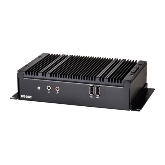
User Manual 1.4 I/O Arrangement ( Front Side ) Power Audio USB2.0 Button Port Power Button Press this button to turn on the system. Audio Port Green connector means LINE OUT / Pink connector MIC IN . USB 2.0 Port Definition USB- USB+... - Page 12 This port can be connected to the DVI monitor via the external DVI-I connector. When connecting VGA monitor, you need an exclusive special DVI to VGA adapter (only offered by Arestech) . HDMI Port This port can be connected to the HDMI monitor. (HDMI v1.3) Users can connect DVI-I and HDMI in the same time (Dual Display), but cannot support 3-display because of Intel chipset's constraint.
- Page 13 User Manual USB 2.0 Port Definition USB- USB+ Basically, USB2.0 supports 0.5A @ 5 V COM Port (RS-232 only) Definition Definition Page 7...
- Page 14 User Manual LAN Port This port can be connected to the Ethernet via RJ-45 connector . 10/100BASE-T: Definition Pin Definition TX_D0+ TX_D0- RX_D1- RX_D1+ 1000BASE-T: Definition Pin Definition TX_D0+ BI_D2- TX_D0- RX_D1- RX_D1+ BI_D3+ BI_D2+ BI_D3- Activity/Link LED Status Description No Link Blinking Data Activity Link...
- Page 15 User Manual Antenna SMA Hole This hole is reserved for antenna SMA connector . If customer select a 3G or a WIFI module , there will be SMA connectors. If customer doesn't select any wireless module, this hole will be reserved. Page 9...
-
Page 16: Mechanical Dimensions
User Manual 1.5 Mechanical Dimension Front Side Dimension Top Side Dimension Page 10... - Page 17 User Manual Back Side Dimension Bottom Side Dimension Page 11...
-
Page 18: Chapter2. System Setup
User Manual Chapter2. System Setup 2.1 Installation Procedure 1. Connecting Power Cord The BOX PC can only be powered through an DC electrical outlet (12 V). Be sure to handle the power cord by holding the plug end only. Follow these procedures to connect the power cord: (1) Connect the male end of the power cord to the DC-In connector of BOX PC. -
Page 19: Installing Change 2.5" Hdd/Ssd
User Manual 2.2 Installing Change 2.5" HDD/SSD Step 1. Unfasten the screw on the bottom of the BOX PC Step 2. Open the bottom cover of the BOX PC. Step 3. Unplug the SATA and SATA power cable. Page 13... - Page 20 User Manual Step 4 . Unfasten the 4 screws on the HDD bracket and install a new one. Page 14...
-
Page 21: Installing Memory / Msata Ssd/ Pcie Module Osd Function
User Manual 2.3 Installing Memory / mSATA SSD/ PCIe Module Step 1. Unfasten the 4 screws on the top of the BOX PC. Memory Slot PCIe/mSATA Slot Step 2. You will see a Memory (slot) and a PCIe (card/slot) . Step 3. -
Page 22: Installing Mounting Bracket
User Manual 2.4 Installing Mounting Bracket Install the mounting bracket on the left side and right side of the BOX PC. Warning ! Be sure to tighten the total 4 screws on the bracket. Page 16... -
Page 23: Chapter 3: Bios Setting
User Manual Chapter 3. BIOS Setting 3.1 Main Menu Once you enter AMI UEFI BIOS Setup Utility, the Main Menu will appear on the screen providing an overview of the basic system information. BIOS Information Shows system information including UEFI BIOS version, model name, marketing name, built date, etc. -
Page 24: Advanced Menu
User Manual 3.2 Advanced Menu The Advanced Menu allows you to configure the settings of CPU, Super I/O, Power Management, and other system devices. 1. Beware of that setting inappropriate values in items of this menu may cause system to malfunction. 2. - Page 25 User Manual Serial Port 1 Configuration Serial Port This item enables or disables Serial Port (COM). Options: Enabled (Default) / Disabled Change Settings This item allows you to select an optimal setting for Super IO device. Options: Auto (Default) / IO=3F8h; IRQ=4 / IO=3F8h; IRQ=3, 4, 5, 6, 7, 9, 10, 11, 12 / IO=2F8h;...
- Page 26 User Manual 3.2.3 CPU Configuration Active Processor Cores This item sets number of cores to enable in each processor package Options: All (Default) / 1 Limit CPUID Maximum When the computer is booted up, the operating system executes the CPUID instruction to identify the processor and its capabilities.
- Page 27 User Manual cache line immediately available if the processor requires it as well. Options: Enabled (Default) / Disabled Intel Virtualization Technology Virtualization Technology can virtually separate your system resource into several parts, thus enhance the performance when running virtual machines or multi interface systems.
- Page 28 User Manual 3.2.4 PPM Configuration EIST This item enables or disables Intel SpeedSteps. Options: Enabled (Default) / Disabled CPU C state Report This item enables or disables CPU C state report to OS. Options: Enabled (Default) / Disabled Enhanced C state This item enables or disables Enhanced CPU C state Options: Enabled (Default) / Disabled Max CPU C-state...
- Page 29 User Manual 3.2.5 SATA Configuration Serial-ATA (SATA) This item enables/disables Serial ATA Device. Options: Enabled (Default) / Disabled SATA ODD Port This item selects SATA ODD Port Options: No ODD (Default) / Port0 ODD / Port1 ODD SATA Mode This item determines how SATA controller(s) operate. Options: IDE (Default) / AHCI Serial-ATA Port 1 This item enables/disables Serial ATA Port 1...
- Page 30 User Manual 3.2.6 Network Stack Configuration Network Stack This item enables or disables UEFI network stack Options: Disabled (Default) / Enabled Note: The following items appear only when you set the Network Stack function to [Enabled] IPv4 PXE Support This item enables or disables IPv4 PXE Boot Support. If disabled IPv4 booth option will not be created.
- Page 31 User Manual 3.2.7 CSM Configuration CSM Support This item enables or disables CSM Support Options: Disabled (Default) / Enabled Note: The following items appear only when you set the CSM Support to [Enabled] GateA20 Active Upon Request – FA20 can be disabled using BIOS services. Always – do not allow disabling GA20;...
- Page 32 User Manual This option controls the execution of UEFI and Legacy Storage OpROM Options: Legacy only (Default) / Do not launch / UEFI only / Legacy first / UEFI first Video This option controls the execution of UEFI and Legacy Video OpROM Options: Legacy only (Default) / Do not launch / UEFI only / Legacy first / UEFI first Other PCI devices...
- Page 33 User Manual Options: Disabled (Default) / Enabled USB Mass Storage Driver Support The item allows you to enable or disable USB Mass Storage Driver Support. Options: Enabled (Default) / Disabled USB transfer time-out The time-out value for Control, Bulk, and Interrupt transfers. Options: 20 sec (Default) / 1 sec / 5 sec / 10 sec Device reset time-out The item sets USB mass storage device Start Unit command time-out.
-
Page 34: Chipset Menu
User Manual 3.3 Chipset Menu This section describes configuring the PCI bus system. PCI, or Personal Computer Interconnect, is a system which allows I/O devices to operate at speeds nearing the speed of the CPU itself uses when communicating with its own special components. 3.3.1 North Bridge Intel IGD Configuration Integrated Graphics Device... - Page 35 User Manual by the Internal Graphics Device Options: 64M (Default) / 96M / 128M / 160M / 192M / 224M / 256M / 288M / 320M / 352M / 384M / 416M / 448M / 480M / 512M DVMT Total Gfx Mem This item selects DVMT5.0 Total Graphic Memory size used by the Internal Graphics Device.
- Page 36 User Manual 3.3.2 South Bridge Azalia HD Audio Azalia Controller This item controls detection of the Azalia device. Disabled = Azalia will be unconditionally disabled. Enabled = Azalia will be unconditionally Enabled. Auto = Azalia will be enabled if present, disabled otherwise. Options: Enabled (Default) / Disabled Azalia HDMI Codec This item enables or disables internal HDMI codec for Azalia.
- Page 37 User Manual USB port X settings. Options: Enabled (Default) / Disabled USB Port 0/1/2/3 This item enables or disables USB Port 0. Options: Enabled (Default) / Disabled PCI Express Configuration Onboard LAN This item enables or disables Onboard PCIE LAN. Options: Enabled (Default) / Disabled Onboard LAN Ootion ROM This item enables or disables the Boot Option for Legacy Network Devices.
-
Page 38: Security Menu
User Manual 3.4 Security Menu Administrator Password This item sets Administrator Password. User Password This item sets User Password. Secure Boot Secure Boot can be enabled if 1. System running in user mode with enrolled Platform Key(PK) 2.CSM function is disabled. Options: Disable (Default) / Enabled Key Management Enroll All Factory Default Keys... - Page 39 User Manual Append Var to DB – Allows you append Var to DB. Authorized Timestamps Database (DBT) Delete DBT – Allows you to delete the DBT file from your system. Set new DBT – Allows you set new DBT file. Append Var to DBT –...
-
Page 40: Boot Menu
User Manual 3.5 Boot Menu Setup Prompt Timeout This item sets number of seconds to wait for setup activation key. Options: 2 (Default) Bootup NumLock State This item selects the keyboard NumLock state. Options: On (Default) / Off Full Screen Logo Display This item allows you to enable/disable Full Screen Logo Show function. -
Page 41: Exit Menu
User Manual 3.6 Exit Menu This menu allows you to load the optimal default settings, and save or discard the changes to the BIOS items Discard Changes and Exit Abandon all changes made during the current session and exit setup. Save Changes and Reset Reset the system after saving the changes. - Page 42 User Manual Page 36...
Need help?
Do you have a question about the BPC-3022 and is the answer not in the manual?
Questions and answers