Table of Contents
Advertisement
Quick Links
Advertisement
Table of Contents
Troubleshooting

Subscribe to Our Youtube Channel
Related Manuals for BestCode NExT 8 Series


Summary of Contents for BestCode NExT 8 Series
- Page 1 A complete range of small and large character printing systems. Series 8 Continuous Ink Jet Printers print high speed, reliable lot/date, sell-by date and other identifying marks and codes on a wide range of substrates, including plastic, glass, paper and more. Version 01.04.01.15+ January 2019...
- Page 3 Copyright January 25th, 2019 by BestCode LLC (henceforth referred to as BestCode). All rights reserved. The information in this document is confidential, and the sole property of BestCode. It may not be reproduced in whole, or in part, nor may any of the information contained therein be disclosed without the prior consent of BestCode. A recipient may not solicit, directly or indirectly (whether through an agent or otherwise) the participation of another institution or person without the prior approval of BestCode.
- Page 4 Product Safety and Compliance Information The BestCode Next Series 8 Printer is tested and certified to the following standards: European Directive(s) Low Voltage Equipment Directive (2014/35/EU) BestCode Side Label Electromagnetic Compatibility Directive (2014/30/EU) European Standard(s) EN 60950-1:2006/A11:2009/A1:2010/A12:2011/A2:2013 EN 55032:2012 EN 55024:2010...
- Page 5 How to use this manual This manual is intended to be used by BestCode trained distributors. The purpose of this manual is to supplement BestCode provided training on how to correctly use the Next Series 8 Printer. This manual contains information on how to select the...
- Page 6 This information contained in this manual is not intended for end users and should never be used by untrained individuals. Only BestCode trained individuals should perform service or maintenance on any of the BestCode Next Series 8 CIJ Printers. Work performed by unauthorized individuals will damaged and void the warranty of the Printer.
- Page 7 PERSONAL INJURY & EQUIPMENT DAMAGE: When connected to Supply Power, this Printer produces Lethal Voltages. Only BestCode trained individuals should service or maintain the Printer. Follow all local safety codes and regulations. Unless necessary, always disconnect the Printer from Supply Power when performing maintenance.
- Page 8 PERSONAL INJURY & EQUIPMENT DAMAGE: Do not use any power entry cable that is not provided by BestCode. Power entry cables must have 3 prongs, live, neutral, and ground provided. Power socket must provide reliable earth ground. Power entry cable, socket, and power entry module must remain clean and dry.
- Page 9 Printer and can potentially cause serious injury or death. See SDS for proper vapor handling instructions. ™ CodeProtect BestCode Warranty and Support BestCode products are delivered with a 2 Year Manufacturer’s Limited Warranty. Call or email for detailed warranty information. Distributors should email support@bestcode.co for all warranty questions.
-
Page 11: Table Of Contents
Table of Contents SYSTEM OVERVIEW ................................1 ..............................1 ERIES YSTEM Controller .................................... 2 Printhead..................................... 4 ................................5 ODEL ELECTION UIDE Speed Selection ................................... 5 Environment Selection ................................ 9 Printhead Selection ................................9 SYSTEM SETUP ................................... 10 ................................10 ONTROLLER OUNTING Controller Mounting Safety ............................... - Page 12 ..................................46 ERVICE CREEN Calibrate .................................... 47 Fluidic ....................................48 Tools ....................................48 Status ....................................54 Event Log ................................... 55 MAINTAINING THE NEXT SERIES 8 SYSTEM ........................56 ................................56 DDING MART LUIDS Information on Fluids and Tanks ............................56 When to Add Ink ................................
- Page 13 Multiple Version Per Stick ............................... 165 Required Tools................................. 165 Firmware Loading Process .............................. 166 Firmware Load Troubleshooting ............................. 173 ....................................178 OOLS BitFontEditor ................................... 178 BestCode Keymaker ................................ 181 BestCode Translator ................................ 183 Graphics ..................................186 ................................ 188 EMOTE OMMUNICATION ................................. 188...
-
Page 15: System Overview
BestCode Next Series 8 System The BestCode Next Series 8 CIJ printers are technologically innovative systems for providing state-of-the art tracking and coding information. The Next Series 8 consists of a family of CIJs, each with a range of special features. -
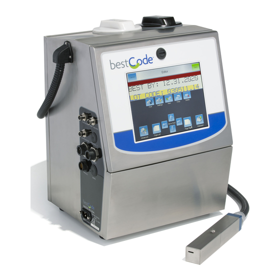
Page 16: Controller
25-0004-06 Makeup Fill cap 27-0005-04W Ink Fill cap 27-0005-04B *This part is non-replaceable Height: 19.4” (493mm) Width: 15.4” (392mm) Depth: 12.5” (318mm) Dry Weight: 45 lbs (20.4 kg) BestCode Next Series 8 Technical Manual January 2019 Page 2 of 205... - Page 17 Ink Tank 20-0012-01 SmartFill Makeup Cup 20-0025-01 Ink Pump 32-0001-01 32-0003-01 for Opaque Valve Manifold Assembly 20-0040-01 Varies by Generation Viscometer Assembly 20-0015-01 Makeup Tank 20-0013-01 BestCode Next Series 8 Technical Manual January 2019 Page 3 of 205...
-
Page 18: Printhead
*This part is non-replaceable Length: 9” (227.7mm) Height: 1.5” (38.1mm) Width: 1.5” (38.1mm) Umbilical Length: 9’ 10” (3m) Available in 15ft (4.5m) Micro printhead is same length as shown above. BestCode Next Series 8 Technical Manual January 2019 Page 4 of 205... -
Page 19: Model Selection Guide
This section is to identify key elements in selecting the correct Next Series 8 System by application requirements. Speed Selection Maximum print speed is important to know when selecting a printer. BestCode Next Series 8 Technical Manual January 2019 Page 5 of 205... - Page 20 / second Resolution is the number of rasters in 1 inch of print. 88,88SS, 88SHS, Model 81, 82 88FG, 88SM 88SHS1 88SHSOP 88SOP Speed Faster Fastest Ultra-Fast BestCode Next Series 8 Technical Manual January 2019 Page 6 of 205...
- Page 21 On multiline templates (2L7, 2L9, 2L12) the C/s value is expressed in characters produced on all lines per second. 88,88SS, 88SHS, Model 81, 82 88FG, 88SM 88SHS1 88SHSOP 88SOP BestCode Next Series 8 Technical Manual January 2019 Page 7 of 205...
- Page 22 Resolution is the number of rasters in 1 inch of print. On multiline templates (3L7, 3L9, 4L7, 5L5) the C/s value is expressed in characters produced on all lines per second. **************************************************** BestCode Next Series 8 Technical Manual January 2019 Page 8 of 205...
-
Page 23: Environment Selection
System runs on compressed air and prevents all dust and water from entering into the electronics area of the cabinet. Includes air drier attached to system. -POSAIR Add on air pump for prevent dust, dirt, or water build up in the printhead. BestCode Next Series 8 Technical Manual January 2019 Page 9 of 205... -
Page 24: System Setup
PERSONAL INJURY & EQUIPMENT DAMAGE: Do not use any power entry cable that is not provided by BestCode. Power entry cables must have 3 prongs, live, neutral, and ground provided. Power socket must provide reliable earth ground. Power entry cable, socket, and power entry module must remain clean and dry. -
Page 25: Ideal Controller Mounting
PERSONAL INJURY & EQUIPMENT DAMAGE: When connected to Supply Power, this Printer produces Lethal Voltages. Only BestCode trained individuals should service or maintain the Printer. Follow all local safety codes and regulations. Unless necessary, always disconnect the Printer from Supply Power when performing maintenance. -
Page 26: Printhead Mounting
WARNING EQUIPMENT DAMAGE: The printhead should never be submerged in Cleaner. This can cause un-repairable damage to the printhead. The printhead must be dry before starting the Printer. BestCode Next Series 8 Technical Manual January 2019 Page 12 of 205... -
Page 27: Ideal Printhead Mounting
1/16”-1/2” inch. 4. Keep printhead square to the product to prevent print distortion. A 5°-10° angle between head and product may be necessary in high static environments. BestCode Next Series 8 Technical Manual January 2019 Page 13 of 205... -
Page 28: Pre-Power Up Guide
The red tube is on the pressure side of the pump, and flows into the main ink filter. Verify the tube connects directly to the main BestCode Ink Filter. 3. Remove the Red cap from the tube. 4. Wet the pump fitting o’ring with cleaner and firmly press the red tube into the red fitting on the pump. -
Page 29: Commissioning
2. Select the ink type that matches the ink to be installed and save 3. Press the Commission System button to Save 4. Check the Help Screen to confirm BestCode Next Series 8 Technical Manual January 2019 Page 15 of 205... -
Page 30: Adding Fluids
5. After the Success prompt, remove the cap and press the bottle firmly into the Makeup Smart Fill Cup. 6. Press OK after the bottle has completely drained. Smartfill Troubleshooting Here BestCode Next Series 8 Technical Manual January 2019 Page 16 of 205... -
Page 31: First Time Jet Start
5. Stop the Jet, then perform the backflush nozzle routine up to 6 times. Backflush guide Here 6. Dry the printhead, then start the Jet normally with Errors, High Voltage and Phase enabled. BestCode Next Series 8 Technical Manual January 2019 Page 17 of 205... -
Page 32: Verify The Modulation
If the print is not acceptable, perform a modulation calibration: Guide Here 5. Return the Modulation to the set point and inspect the drop breakup. BestCode Next Series 8 Technical Manual January 2019 Page 18 of 205... -
Page 33: Basic Operations
Clean Start or Stop. The system will intelligenty switch the Clean Start & Stop method to quick start to prevent the operator from adding too much makeup. BestCode Next Series 8 Technical Manual January 2019... -
Page 34: Selecting A Message For Print
3. Press the Select button 4. The selected message will now be the actively printed message Note: The BESTCODE and BESTCODE-AUTO are calibration messages. They cannot be edited or deleted. BestCode Next Series 8 Technical Manual January 2019 Page 20 of 205... -
Page 35: Navigating The Next Series 8 User Interface
Contact information on this screen be setup in the Setup window. can be translated using the translator tool to give on screen distributor contact information to the operator. BestCode Next Series 8 Technical Manual January 2019 Page 21 of 205... - Page 36 Keyboards, Date/Time, modify operating parameters and Networking, Operator Passwords, gives access to Technician features and Peripheral options when logged in with the Technician Level Password. BestCode Next Series 8 Technical Manual January 2019 Page 22 of 205...
-
Page 37: Message Creation
1. Create a new message. Name it, and press confirm. Text Field Enters directly into the Message Editor and allows characters to be typed directly into the message. BestCode Next Series 8 Technical Manual January 2019 Page 23 of 205... -
Page 38: Autocode Field
Add automatically updating Time codes to the message. Anything to do with Hours, Minutes, and Seconds. Date Codes Add automatically updating Date codes to the message. Anything to do with Years, Months, Weeks, or Days. Normal Date BestCode Next Series 8 Technical Manual January 2019 Page 24 of 205... - Page 39 Counts the number of times the message has been printed. Counter 1-4 Programmable counters. Shift Codes Adds codes for tracking plant shift and shift at the time of Print. Can be programmed in the Advance Message Settings BestCode Next Series 8 Technical Manual January 2019 Page 25 of 205...
-
Page 40: User Define
Allow or disallow entry of less than the number of characters defined by the Length entry. Block Field Example Block Length:5 Gap: 2 Block Length Specifies the number of rows of full vertical print Specifies the number of blank rows after the print BestCode Next Series 8 Technical Manual January 2019 Page 26 of 205... -
Page 41: Barcode Field
Brings up the on screen keyboard for typing in text to the barcode. AutoCode Field Insert Autocode data into the barcode User Define Insert a User Define field into the barcode. BestCode Next Series 8 Technical Manual January 2019 Page 27 of 205... - Page 42 Multi-Information start code Allows custom barcode creation FNC1 for integration into existing Application Identifier scanning systems. Application Identifier Data FNC1 Application Identifier Application Identifier Data Checksum Stop Code BestCode Next Series 8 Technical Manual January 2019 Page 28 of 205...
- Page 43 Depth, thickness, height, or 3rd Electronic serial number for cellular 8002 dimension, meters telephones Area, square meters FACT identifiers (internal applications) Internal use (raw materials, packaging, Volume, liters components BestCode Next Series 8 Technical Manual January 2019 Page 29 of 205...
- Page 44 QR Code Sizes are expressed as Versions. The Next Series 8 features Version 1, Version 2, and Version 3. Size / Version Matrix Size Max Numeric Max Alphanumeric Max Binary Max Kanji 21x21 25x25 29x29 BestCode Next Series 8 Technical Manual January 2019 Page 30 of 205...
-
Page 45: Graphic Field
Graphic Field Allows the operator to add graphics into the message. Graphics must be created on a a computer and loaded into the device via USB. Instructions Here BestCode Next Series 8 Technical Manual January 2019 Page 31 of 205... -
Page 46: Message Editor
Normal, Mirror, Flip, Mirror Flip, Rotation Rotates the print on the screen Tower CCW, Tower CW Changes the number set used for the Multi-language options. Auto-Numerals selected Autocode field. BestCode Next Series 8 Technical Manual January 2019 Page 32 of 205... - Page 47 Moves the Editor preview window to the right Moves the selected field up. Fields can also be selected and moved using the Move Field drag and drop touch screen feature. BestCode Next Series 8 Technical Manual January 2019 Page 33 of 205...
- Page 48 Changes the number set for all Autocodes in the message. Inverted Print Prints all of the area that would normally be blank and leaves the Prints the character normally. character un-printed. BestCode Next Series 8 Technical Manual January 2019 Page 34 of 205...
- Page 49 Change to the next shift and set a new time. This will end the settings of the previous shift, and allow creating settings for the shift at the new time of day. BestCode Next Series 8 Technical Manual January 2019...
- Page 50 The Printer High Voltage will disable when the counter reachers the End Count value. Print Off Then will prevent the printer from coding any more product until the counter is reset. BestCode Next Series 8 Technical Manual January 2019 Page 36 of 205...
- Page 51 MESSAGE SELECT 5 MESSAGE SELECT 6 MESSAGE SELECT 7 GROUND BCD Table for 0-25 X means shorted to Pin 14, O means open to Pin 14. ID Number ID Number BestCode Next Series 8 Technical Manual January 2019 Page 37 of 205...
-
Page 52: Count Screen
Counter 1-4 These are setup in the message editor. See 0-999,999,999 here Counters can be reset OR manually typed in using the buttons next to each counter. BestCode Next Series 8 Technical Manual January 2019 Page 38 of 205... -
Page 53: Message Screen
Create a new message the message name Shows the currently selected message. Select the highlighted message Edit the currently selected message Deleted the currently selected message. BestCode Next Series 8 Technical Manual January 2019 Page 39 of 205... -
Page 54: Adjust Screen
Speed Used to increase the maximum print speed. Fast Best Quality Fastest Higher Speed, OK Quality Faster Faster than Fast, Good Quality Ultra-Fast Fastest Print, Readable Code BestCode Next Series 8 Technical Manual January 2019 Page 40 of 205... -
Page 55: Speed Screen
Check on the Status screen to see if Missed Prints, Missed Encoder, or Missed Photo Eye are increasing. Continue to increase width and selecting faster print speed until these values stop incrementing. BestCode Next Series 8 Technical Manual January 2019... -
Page 56: Clean Screen
Selects the Keyboard/s to be used for creating messages. Up to 4 keyboards can be used. Press the Globe button on any keyboard to change to the next Keyboard. BestCode Next Series 8 Technical Manual January 2019 Page 42 of 205... -
Page 57: Date / Time
Bytes Sent Logs how much data has been sent from the Printer to the remote device. Helpful is diagnosing lost confirmation or data requests from the remote device. BestCode Next Series 8 Technical Manual January 2019 Page 43 of 205... -
Page 58: Peripherals
Print begins when the Photoeye state is down PE 1 Option Always ON PE 1 Setup Choose which counters should or should not increment when PE 1 is triggered. BestCode Next Series 8 Technical Manual January 2019 Page 44 of 205... - Page 59 When a Warning (yellow) occurs on screen, the Relay will be closed circuit. Fault When a Fault (Red) occurs on screen, the Relay will be closed circuit. Relay wiring information can be found here BestCode Next Series 8 Technical Manual January 2019 Page 45 of 205...
-
Page 60: Password
Service Screen The service screen is for the operator to adjust machine settings and perform service on the machine. BestCode Next Series 8 Technical Manual January 2019 Page 46 of 205... -
Page 61: Calibrate
50 PSI, 24 RPS (+/- 5 RPS) Phase Point 0-16 Phase Width Quality 90-100% Phase Threshold 13-39 Viscometer See Status Screen Target 4.5 cP Actual 0.0cP, 0.0s 2.5-6.0cP, 45.0-115s Printhead 0-60C Electric 0-60C BestCode Next Series 8 Technical Manual January 2019 Page 47 of 205... -
Page 62: Fluidic
Firmware Update Used to load software via USB only. Not recommended. Technician Accesses technician tools. Must be logged in using Technician Level Password. BestCode Next Series 8 Technical Manual January 2019 Page 48 of 205... - Page 63 Reset Phase If the Phase Threshold is less than 10 or above 40, this button can be used to set it back to an Threshold acceptable point. BestCode Next Series 8 Technical Manual January 2019 Page 49 of 205...
- Page 64 When the counter button is pressed, all counters in the current message will be reset. Screen Opens the screen calibration screen. Calibrate BestCode Next Series 8 Technical Manual January 2019 Page 50 of 205...
- Page 65 Resets the counter on the total number of messages that the printer has printed. Used mainly for rental purposes. Restore Factory Restore the machine to Factory Default. BestCode USB stick with correct Firmware Version must be Defaults installed. Resets the Calibration values (Modulation, Pressure, Charge), Deletes all Messages and Graphics, Resets the Setup (Date/Time, Name, Keyboards, Language, Peripheral Settings, Network, and Passwords), Sets all Technician Features.
- Page 66 Allows maximum flexibility in the message editors, allows row by positioning inside the message row positioning on the Font. editor. Helpful for quickly creating multi-line print. Delete All Deletes all of the graphics on the printer. Graphics BestCode Next Series 8 Technical Manual January 2019 Page 52 of 205...
- Page 67 System will not be saved. Ink Type Scroll up and down to match the ink type desired to be used in the machine. System Flush See instructions here BestCode Next Series 8 Technical Manual January 2019 Page 53 of 205...
-
Page 68: Status
Missed Prints Missed Encoder Missed Total Prints Photo Eye 0-999999999999 Temperature Electric Printhead 0-60C 0-60C System Power On Run Time Filter Makeup 0-175200.0 Hrs 0-175200.0 Hrs 0-10000.00 1-100 1-100 BestCode Next Series 8 Technical Manual January 2019 Page 54 of 205... -
Page 69: Event Log
Save Saves all of the Log files to a USB thumbdrive. See the troubleshooting section here for information on the Event Codes. BestCode Next Series 8 Technical Manual January 2019 Page 55 of 205... -
Page 70: Maintaining The Next Series 8 System
Makeup Tank can hold 2 bottles of Makeup. Makeup Overfilling of the tank will cause an error and requires that the tanks be completely emptied, and fresh ink be installed. BestCode Next Series 8 Technical Manual January 2019 Page 56 of 205... -
Page 71: When To Add Ink
When to Add Ink The BestCode Next Series 8 CIJ will begin requesting an Ink bottle be added when the Float switch in the Ink Tank is in the low state. An on-screen prompt, Ink Warning, 10-0003 will occur every 6 minutes while the Ink Tank is in this State. -
Page 72: When To Add Makeup
11. Press OK on the Success screen prompt (10-0001) When to Add Makeup The BestCode Next Series 8 CIJ will allow a Makeup bottle to be added when the Float switch in the Makeup Tank is in the OK state. -
Page 73: How To Add Makeup
8. Insert the bottle and press firmly to break the foil seal. 9. Wait for 1-2 minutes for the bottle to drain 10. Discard the empty Makeup bottle in accordance with local regulation. BestCode Next Series 8 Technical Manual January 2019 Page 59 of 205... -
Page 74: Cleaning The Printhead
Backflush nozzle should be performed if the print looks bad. How to wash the Printhead Be familiar with proper safety information for handling fluids. 1. Place the Printhead into the Printhead Clean Station (P/N 40-0020-01) BestCode Next Series 8 Technical Manual January 2019 Page 60 of 205... -
Page 75: Back Flushing The Nozzle
Be familiar with proper safety information for handling fluids. 1. Place the Printhead into the Printhead Clean Station (P/N 40-0020-01) 2. Press the Back Flush button (Service screen OR Clean screen). BestCode Next Series 8 Technical Manual January 2019 Page 61 of 205... -
Page 76: Advanced Nozzle Cleaning
Place jar with cleaner and nozzle into a bath of warm water in the Ultra-Sonic cleaner. Cleaner is non-flammable. Run the ultra-sonic bath for 2 minutes maximum. Remove the nozzle from the Nozzle Clean Solvent and clean with MEK before re-installing. BestCode Next Series 8 Technical Manual January 2019 Page 62 of 205... -
Page 77: Printhead Clean Routine
3. Inspect the printhead as the routine runs. 4. Make sure the tubes on the drop generator and the gutter are completely clean by the end of the routine. BestCode Next Series 8 Technical Manual January 2019 Page 63 of 205... -
Page 78: Servicing The Next Series 8 System
†Filter life is dependent on environment. In wet, dirty, dusty environments, filters life will be ½ of the time listed above. Each Kit comes with instructions for replacing the filter. BestCode Next Series 8 Technical Manual January 2019 Page 64 of 205... - Page 79 (use 5/8” open end wrench) 7. Allow the filter to drain, then dispose of the filter and waste ink in accordance with local regulation. BestCode Next Series 8 Technical Manual January 2019 Page 65 of 205...
- Page 80 SmartFill screen 11. Press Read SmartFilter Label 12. Confirm on the Status screen that the new filter was installed correctly. 13. Start the Jet and check for leaks. BestCode Next Series 8 Technical Manual January 2019 Page 66 of 205...
- Page 81 The inlet should be 4” and the outlet tube should be 17”. If the Pre-Pump filter is not mounted vertically, Phase Faults will occur. 4. Follow directions from Filter Instructions here Maintenance, Step 3-8. BestCode Next Series 8 Technical Manual January 2019 Page 67 of 205...
- Page 82 3. Remove the Makeup Tank form the fluidic compartment 4. Remove the Makeup pickup from the Makeup Tank 5. Disconnect the Makeup feed tube from the Main Ink Manifold BestCode Next Series 8 Technical Manual January 2019 Page 68 of 205...
- Page 83 5. Remove the tube from the 1/8” push to connect PH Feed/Dampener filter input fitting Discard the used dampener filter and waste fluid in accordance with local regulation BestCode Next Series 8 Technical Manual January 2019 Page 69 of 205...
- Page 84 Procedure Time: 1 Minute 1. Remove the filter wire spring. 2. Insert the 46-5004-01 Filter, Air frame backing into the Air Filter box. BestCode Next Series 8 Technical Manual January 2019 Page 70 of 205...
- Page 85 3. Insert the Air Filter 46-0004-01. Note: Smooth side faces inward. 4. Latch in the Air Filter frame hinge 5. Close the latch and press in the filter spring. BestCode Next Series 8 Technical Manual January 2019 Page 71 of 205...
-
Page 86: Fluidic Service Routines
3. Locate and disconnect the SmartFill Cup Assembly antenna coax cables. Color Codes: Black = Ink SmartFill Cup Assembly Blue = SmartFilter Reader Assembly White = Makeup SmartFill Cup Assembly BestCode Next Series 8 Technical Manual January 2019 Page 72 of 205... - Page 87 4. Push the SmartFill antenna coax cable grommet through the middle controller wall and remove the SmartFill cup from the machine. BestCode Next Series 8 Technical Manual January 2019 Page 73 of 205...
-
Page 88: Venturi Replacement
2. Remove the Venturi inlet tube 3. Remove the venturi from the Ink Tank and place it into a beaker. 4. Use Cleaner to insert the new venturi into the Ink Tank BestCode Next Series 8 Technical Manual January 2019 Page 74 of 205... - Page 89 5. Install the Tubes from the old venturi into the new venturi. Tube plumbing is critical to the system operation. Pay close attention to the correct inlet for each color coded tube. BestCode Next Series 8 Technical Manual January 2019 Page 75 of 205...
-
Page 90: Venturi Cleaning
Procedure Time: 5 minutes 1. Remove the Venturi from the Ink Tank 2. Remove the Venturi Return Tube 3. Clean the venturi through each port BestCode Next Series 8 Technical Manual January 2019 Page 76 of 205... - Page 91 Some staining is normal. If side ports cannot be cleaned with Cleaner, replace the entire Venturi. 6. Re-assemble the Venturi. The venturi may now be re-installed into the machine. BestCode Next Series 8 Technical Manual January 2019 Page 77 of 205...
-
Page 92: Pump Replacement
3. Locate and remove the 2 Pump mounting screws. 4. Remove the pump from the back of the machine and disconnect the tubes. BestCode Next Series 8 Technical Manual January 2019 Page 78 of 205... - Page 93 6. Install the new pump, paying close attention to the pump fitting orientation. Pre-pump filter side connects to the black marked fitting (pump inlet). BestCode Next Series 8 Technical Manual January 2019 Page 79 of 205...
- Page 94 Red side fitting connects to the main ink filter tube (pump outlet). 7. Mount the Pump and make the electrical connection to the main board. BestCode Next Series 8 Technical Manual January 2019 Page 80 of 205...
-
Page 95: Viscometer Replacement
T10 Torx driver Gray 5. Disconnect the Purple, Brown, and Grey tubes. 6. Connect the Purple, Brown, and Grey tubes to the new Viscometer Brown Violet BestCode Next Series 8 Technical Manual January 2019 Page 81 of 205... - Page 96 8. Install the viscometer cable to the machine. Plug together 9. Cap the removed viscometer so it does not dry Plug with 10. Test the Viscometer for accurate reading. BestCode Next Series 8 Technical Manual January 2019 Page 82 of 205...
-
Page 97: Cleaning The Viscometer
5. Ensure viscometer restrictor is free of debris. 6. Ensure that ball is able to move in the viscometer. 7. Re-assemble 8. Follow Viscometer replacement steps to install and test the viscometer. BestCode Next Series 8 Technical Manual January 2019 Page 83 of 205... -
Page 98: Ink Manifold Replacement
2. Remove the valve cable connections and Pressure transducer cable connection 3. Remove the 2 manifold mounting screws 4. Disconnect the tubes and install into the new manifold 1 at a time. BestCode Next Series 8 Technical Manual January 2019 Page 84 of 205... - Page 99 5. Install the remaining tubes into the new manifold 6. Mount the manifold 7. Connect the Cables 8. Test the Valves 9. Start the Jet & inspect for leaks BestCode Next Series 8 Technical Manual January 2019 Page 85 of 205...
-
Page 100: Ink Valve Replacement
1. Remove the valve cable connection. 2. Remove the mounting screws 3. Clean the port with Cleaner 4. Ensure that gasket is in the new valve. 5. Install the New Valve BestCode Next Series 8 Technical Manual January 2019 Page 86 of 205... -
Page 101: Ink Valve Cleaning
4. If valve does not click, turn off the valve, then disconnect the valve cable connection. 5. Remove the coil body, and submerge the valve body in cleaner. Wait for 5-10 minutes. BestCode Next Series 8 Technical Manual January 2019 Page 87 of 205... - Page 102 8. With the Valve Open, spray Cleaner through the valve until it runs clean. 9. Re-install the valve. See installation guide here BestCode Next Series 8 Technical Manual January 2019 Page 88 of 205...
-
Page 103: Replacing The Ink Tank
Spraying cleaner on the O-rings will help with inserting them into the tank. 5. Replace the Main Ink Filter See Instructions here. This is critical to prevent re-contamination of the ink tank. BestCode Next Series 8 Technical Manual January 2019 Page 89 of 205... -
Page 104: Flushing The Ink System
Do no-reuse ink. 8. Install SmartFill Ink bottle Flushing the Ink System Contact BestCode for instructional video on System Flushing for long term storage or ink changes. Support@BestCode.co Flushing kit tools can be purchased from BestCode. Order 44-5xxx-01 Kit, Ink Flushing... -
Page 105: Electronic Service Routines
3. Remove all of the cable connections Be careful to pull coax connections straight out from the board. Pulling at an angle can damage the center pin on the connector and on the board. BestCode Next Series 8 Technical Manual January 2019 Page 91 of 205... - Page 106 Static safe cartons are included with each spare Circuit Board. Do not discard them! 6. Install the New Circuit board by aligning the board onto the plastic standoffs. BestCode Next Series 8 Technical Manual January 2019 Page 92 of 205...
- Page 107 9. Power on the system and setup the Ink here for Ink Commissioning Commission Type, Calibrate the here for Modulation Calibration Modulation, set the fluidic system type. here for Fluidic System type BestCode Next Series 8 Technical Manual January 2019 Page 93 of 205...
-
Page 108: Power Supply Replacement
3. Remove the High Voltage jacks from the power supply 4. Remove the Main power entry cable from the power supply BestCode Next Series 8 Technical Manual January 2019 Page 94 of 205... - Page 109 Static safe cartons are included with each spare Power Supply. Do not discard them! 8. Install the HV jack and Power Entry into the new Power Supply. BestCode Next Series 8 Technical Manual January 2019 Page 95 of 205...
- Page 110 11. Connect the Printhead Cable, Printhead Coax Cables, Fan Cable, Power supply cable, LCD Display and Power cables, and Level Switch cables to the main board. BestCode Next Series 8 Technical Manual January 2019 Page 96 of 205...
-
Page 111: Display Replacement
0031-02) and the LCD Ribbon Cable (16- 0032-01) 4. Remove the M5 lock nuts that secure the LCD Display into the Electronics Door using an 8mm nut driver. BestCode Next Series 8 Technical Manual January 2019 Page 97 of 205... - Page 112 8. Place the washer over the LCD Display Bracket, and then thread on the M5 Locknut. Leave the nut slightly loose for adjustment of the LCD Display assembly. BestCode Next Series 8 Technical Manual January 2019 Page 98 of 205...
- Page 113 10. Position the display so that none of the black display edging is visible through the Electronic Door graphic overlay. 11. Tighten the Display Mounting Nuts and secure the Electronic Door Lanyard. BestCode Next Series 8 Technical Manual January 2019 Page 99 of 205...
-
Page 114: Integrating External Peripheral Devices
Integrating External Peripheral devices Alarm Beacon Shaft Encoder Ethernet BestCode Next Series 8 Technical Manual January 2019 Page 100 of 205... - Page 115 5) Repeat the process for the device side, matching device features to the corresponding pins. Use the provided seal and grommet to ensure cable maintains IP 67 Rating. BestCode Next Series 8 Technical Manual January 2019 Page 101 of 205...
- Page 116 220 V DC, 250 V AC Max. carrying current Min. switching capacity (Reference 10µA 10mV DC value) Nominal operating power Single side stable (M type: 400 mW, S type: 200 mW); BestCode Next Series 8 Technical Manual January 2019 Page 102 of 205...
- Page 117 Photocell Auxiliary Serial BestCode Next Series 8 Technical Manual January 2019 Page 103 of 205...
- Page 118 BestCode Next Series 8 Technical Manual January 2019 Page 104 of 205...
- Page 119 Collector Information BestCode Next Series 8 Technical Manual January 2019 Page 105 of 205...
-
Page 120: Printhead Service Routines
Procedure Time: 5 minutes 1. Remove the 2 drop generator side mounting screws 2. Remove the 2 nozzle screws 3. Remove the nozzle. BestCode Next Series 8 Technical Manual January 2019 Page 106 of 205... - Page 121 Nozzle seals are 1 time use. 6. Install a new or the cleaned nozzle 7. Perform jet alignment and modulation Jet Alignment Guide calibration to complete Modulation Calibration Guide BestCode Next Series 8 Technical Manual January 2019 Page 107 of 205...
-
Page 122: Jet Alignment
2. Use a flathead screw driver to move the jet up and down in the gutter hole. Side View 3. Tighten the 2 drop generator side mounting screws once this position is achieved. IDEAL VERTICAL ALIGNMENT BestCode Next Series 8 Technical Manual January 2019 Page 108 of 205... - Page 123 This moves the jet towards and away from the print slot. 3. Tighten the drop generator adjuster screw once this position is achieved. IDEAL HORIZONTAL ALIGNMENT BestCode Next Series 8 Technical Manual January 2019 Page 109 of 205...
- Page 124 MAGNIFIED GUTTER VIEW 4. Confirm jet placement Perfect jet alignment BestCode Next Series 8 Technical Manual January 2019 Page 110 of 205...
-
Page 125: Drop Generator Replacement
2. Remove the black heat shrink over the blue coax cable. 3. Remove the Yellow tube from the Drop generator and the Drop generator feed tube from the Valve Manifold. BestCode Next Series 8 Technical Manual January 2019 Page 111 of 205... - Page 126 After Cutting 6. Slide the clipped back Yellow onto the Drop generator bleed port. 7. Apply heat and push the tube all the way down BestCode Next Series 8 Technical Manual January 2019 Page 112 of 205...
- Page 127 9. Connect the blue coax cable and heat shrink with the included heatshrink. 10. Perform jet alignment and Jet Alignment Guide modulation calibration to complete Modulation Calibration Guide BestCode Next Series 8 Technical Manual January 2019 Page 113 of 205...
-
Page 128: Modulation Calibration
55-65% 45-50 PSI – all acceptable. 88SHSOP (<40% causes Charge Fault) 88HS1 65µ 60-65% (<40% causes Charge Fault) 50 PSI 120V 88SM 40µ 50-55% (<40% causes Charge Fault) BestCode Next Series 8 Technical Manual January 2019 Page 114 of 205... - Page 129 Satellite Satellite drops are caused by the tail of the drop drop breaking off into a smaller drop. BestCode Next Series 8 Technical Manual January 2019 Page 115 of 205...
- Page 130 4. Repeat until a bad print in achieved 5. Set the modulation point to 30V 30V over above the lowest acceptable print. 20V over 10V over Lowest Acceptable BestCode Next Series 8 Technical Manual January 2019 Page 116 of 205...
- Page 131 The best solution is to reduce the charge to and check the Modulation Window. You may have to select a new frequency range, but lower charge will work. BestCode Next Series 8 Technical Manual January 2019 Page 117 of 205...
- Page 132 If the issues shown are present on an 88HS, 88HS1, or 88SM, it may be necessary to reduce the charge % to as low as 40%. Use Height 10 in the adjust screen to increase the print height while maintaining good print quality at charge 40%. BestCode Next Series 8 Technical Manual January 2019...
-
Page 133: Gutter Replacement
1. Pull the gutter tube off of the gutter barb 2. Remove the 2 gutter screws 3. Clean or replace the gutter body. 4. Perform jet alignment Jet Alignment Guide BestCode Next Series 8 Technical Manual January 2019 Page 119 of 205... -
Page 134: Gutter Detect Replacement
2. Remove the heatshrink from the black coax cable. 3. Lift out the gutter detect 4. Pull the white tube out from the back end of the gutter detect. BestCode Next Series 8 Technical Manual January 2019 Page 120 of 205... - Page 135 After Cutting 6. Place the clipped back tube onto the new gutter detect tube 7. Swage tube open slightly with a screw driver. BestCode Next Series 8 Technical Manual January 2019 Page 121 of 205...
- Page 136 8. Install onto the gutter. 9. Apply the new heatshrink over the gutter detect and over the black coax cable connection. BestCode Next Series 8 Technical Manual January 2019 Page 122 of 205...
-
Page 137: Printhead Valve Manifold Replacement
2. Lift up the Manifold 3. Remove the 2 valve mounting screws 4. Remove the tubes from the valve manifold. 5. Make sure the Valve gasket is in place BestCode Next Series 8 Technical Manual January 2019 Page 123 of 205... - Page 138 6. Replace the manifold BestCode Next Series 8 Technical Manual January 2019 Page 124 of 205...
-
Page 139: Printhead Valve Replacement
Wire colors for the Printhead Valve are White/Red/Orange stripe and White/Green/Yellow stripe. There is no wire polarity. 5. Make sure the Valve gasket is in place BestCode Next Series 8 Technical Manual January 2019 Page 125 of 205... - Page 140 6. Reinstall the valve. BestCode Next Series 8 Technical Manual January 2019 Page 126 of 205...
-
Page 141: Printhead Umbilical Replacement
Main CPU Board, the Power Supply, and from the Case ground stud. 2. Pull the printhead harness forward to ensure all of the cables are disconnected from the Main CPU Board. BestCode Next Series 8 Technical Manual January 2019 Page 127 of 205... - Page 142 3. Pull the electronics cables through the middle wall bulkhead knockout/ 4. Remove the umbilical bulkhead fitting from the side of the machine. BestCode Next Series 8 Technical Manual January 2019 Page 128 of 205...
- Page 143 5. Lift out the Ink Manifold and remove the Blue, White, and Yellow tubes. 6. Remove Red tube from the outlet of the PH Feed/Dampener Filter (20- 0019-01) Cap the tubes to reduce the mess. BestCode Next Series 8 Technical Manual January 2019 Page 129 of 205...
- Page 144 8. Pull the umbilical hoses and cables out through the umbilical bulked fitting. 9. Pull the new umbilical tube and wires through the bulkhead fitting BestCode Next Series 8 Technical Manual January 2019 Page 130 of 205...
- Page 145 13. Install the drop generator Drop generator installation shown here 14. Perform up the 6 back flushes 15. Calibrate the modulation Modulation Calibration instructions here 16. Align the jet. Jet Alignment here BestCode Next Series 8 Technical Manual January 2019 Page 131 of 205...
-
Page 146: Troubleshooting The Next Series 8 System
Press OK to Shut Down the machine Solution 2: Press Cancel to close the prompt. Prompt Code Prompt Name Prompt Description 01-0003 Message The message will be erased. Are you sure? BestCode Next Series 8 Technical Manual January 2019 Page 132 of 205... - Page 147 Prompt Description 01-0019 Log Reset Reset SmartFill Log. Are you sure? Solution 1: Press OK to Erase the SmartFill Log. Solution 2: Press Cancel to close the prompt. BestCode Next Series 8 Technical Manual January 2019 Page 133 of 205...
- Page 148 All graphics will be erased. Are you sure? Solution 1: Press OK to delete all graphics. Solution 2: Press Cancel to close the prompt. Prompt Code Prompt Name Prompt Description BestCode Next Series 8 Technical Manual January 2019 Page 134 of 205...
- Page 149 Solution 2: Press Cancel to close the prompt. Prompt Code Prompt Name Prompt Description 07-8001 File Transfer Invalid print memory files were found. Perform Restore function (Service>Tools>Restore) Solution 1: BestCode Next Series 8 Technical Manual January 2019 Page 135 of 205...
- Page 150 Replace the Printhead Umbilical Solution 3: Replace the Power Supply Solution 4: Replace the Main Circuit Board Solution 5: Prompt Code Prompt Name Prompt Description 08-8003 Voltage Modulation voltage below threshold. BestCode Next Series 8 Technical Manual January 2019 Page 136 of 205...
- Page 151 Replace the Printhead Umbilical Solution 6: Replace the Main Circuit Board Prompt Code Prompt Name Prompt Description 0A-8002 Phase Fault Phase signal not detected. Solution 1: See 0A-8001 BestCode Next Series 8 Technical Manual January 2019 Page 137 of 205...
- Page 152 Plug in the -DRY pressure transducer cable to J26 Air Cooler on the Main Circuit Board Increase air pressure or tighten air regular on the -DRY air separator until at least 40 PSI is read on Solution 2: the pressure gauge. BestCode Next Series 8 Technical Manual January 2019 Page 138 of 205...
- Page 153 Measure ink viscosity, if viscosity is less than 1.5cP, replace the ink. Solution 4: Replace the Ink Pump Solution 5: Replace the Pressure Transducer Solution 6: Replace the Viscometer BestCode Next Series 8 Technical Manual January 2019 Page 139 of 205...
- Page 154 If the makeup flows, the Makeup Add valve is clogged open and should be cleaned or replaced. Solution 4: Replace the Viscometer If not using BestCode provided fluids, inspect ink for foaming. This can cause ink to become thin Solution 5: over time.
- Page 155 Solution 2: Try scanning new SmartFill label Solution 3: Check coax cable connections from the SmartFill cup. Solution 4: SmartFill label does not match the command label. Contact BestCode for correct command label. Prompt Code Prompt Name Prompt Description 0F-8002...
- Page 156 Prompt Name Prompt Description 10-8001 Ink Fault SmartFill label not valid for this machine. Solution 1: Label type cannot be used in the BestCode machine. Contact BestCode. Prompt Code Prompt Name Prompt Description 10-8002 Ink Fault SmartFill label not valid for this machine type.
- Page 157 Prompt Code Prompt Name Prompt Description 11-0005 Add Makeup Action Required: Add SmartFill Makeup Action Required: Add SmartFill Makeup Solution 1: See 11-0002. Prompt Code Prompt Name Prompt Description BestCode Next Series 8 Technical Manual January 2019 Page 143 of 205...
- Page 158 Prompt Name Prompt Description 11-8001 Makeup Fault SmartFill label not valid for this machine. Solution 1: Label type cannot be used in the BestCode machine. Contact BestCode. Prompt Code Prompt Name Prompt Description 11-8002 Makeup Fault SmartFill label not valid for this machine setting.
- Page 159 Solution 1: Printhead temperature has exceeded 60°C. Reduce environment temperature. Solution 2: If ambient temperature is not exceeding 50°C, replace the Printhead Umbilical due to faulty temperature sensor. BestCode Next Series 8 Technical Manual January 2019 Page 145 of 205...
-
Page 160: Diagnosing Main Circuit Board Issues
Provides voltage and recieves photocell sensor signal Encoder Provides voltage and recieves encoder signal Provides voltage and recieves photocell sensor signal Alarms Provides voltage and signal to Alarm beacon. BestCode Next Series 8 Technical Manual January 2019 Page 146 of 205... -
Page 161: Fuses
If OFF, 24V supply is compromised. Determine if problem is interal Green (power supply issue) or external (peripheral). If LED is DIM, there is likely a partial short to one of the Peripheral Devices. BestCode Next Series 8 Technical Manual January 2019 Page 147 of 205... -
Page 162: Troubleshooting Cpu Problems
Check LED 2 & 5 for illumination. If dim, 24V supply to peripheral is compromised. Inspect cable connections from J11, J14, J15,J17, J19, P4, and P5 for shorts to ground +3.3V on Encoder using PhotoEye 2 (Illuminates with each pulse) Green BestCode Next Series 8 Technical Manual January 2019 Page 148 of 205... - Page 163 300V supply is compromised. Replace the PSU. Likely will have 0B-0003, 08-8001, 08-8002, or 08-8003 Fault. EHT Voltage Enabled (Enabled when Jet is on) Troubleshooting No LED Solution 1: Enable the HV on the Home Screen. BestCode Next Series 8 Technical Manual January 2019 Page 149 of 205...
-
Page 164: Troubleshooting Fluidic System Problems
31-0001-02 Filter, Model 88 Ink 31-0004-01 Filter, Model 88S Opaque Ink 20-5032-01, Venturi, Next Series 8 Assembly (GEN 2) 40psi 20-5033-01, Venturi, Next Series 8 Assembly (GEN 2) 50psi BestCode Next Series 8 Technical Manual January 2019 Page 150 of 205... - Page 165 Solvent Filter (31-0021-01) 33-0001-02, Valve, 2 Way Ink 34-0003-02, Sensor, Ink Pressure 20-0015-01, Viscometer Assy, Complete This image is rotated 90° BestCode Next Series 8 Technical Manual January 2019 Page 151 of 205...
- Page 166 When tubes lines are shown in this format, it means that the tubes cross but are not connected. Ink from the Red tube is not connected to the blue tube in this symbol. BestCode Next Series 8 Technical Manual January 2019...
- Page 167 8) The Purple Line is Split from the green line to Feed the Viscometer 9) Brown line is on the side opposite the Viscometer Restrictor, and returns Ink to the ink Tank. BestCode Next Series 8 Technical Manual January 2019...
- Page 168 4) A timer is started to measure how long until the Ball passes the Inductive Sensor. 5) The Time is captured and converted to a value in cP. 6) The Target Viscosity is ALWAYS 4.5 cP. BestCode Next Series 8 Technical Manual January 2019 Page 154 of 205...
- Page 169 3) Solvent Add Valve activates for 1 second, then de-activates. 4) This Solvent Add Valve on/off cycle occurs 5 to 6 times in succession depending on Ink thickness. BestCode Next Series 8 Technical Manual January 2019 Page 155 of 205...
- Page 170 6) The Flush Valve activates, and pushes clean solvent out of the drop generator into the gutter to clean the gutter and gutter sensor. 7) The Flush Valve and Gutter Valve de-activate. BestCode Next Series 8 Technical Manual January 2019 Page 156 of 205...
- Page 171 Solvent Add valve is not fully closed. This can steal vacuum from the gutter and prevent it from working correctly. Diagnostic 3 Test the Ink viscosity. Ink Below 2.0cP and Ink above 8.0cP can prevent the vacuum from working correctly. BestCode Next Series 8 Technical Manual January 2019 Page 157 of 205...
- Page 172 Test, then clean or replace the Bleed Valve and Solvent Tank Valve. Check all tube connections for the Orange, Blue and Yellow tubes. Make sure the tube is not clogged by testing each tube with a spray of cleaner. BestCode Next Series 8 Technical Manual January 2019 Page 158 of 205...
-
Page 173: Common Printhead Issues
A drop when hitting the surface will breakup into “many” splash drops. • Splash drops are charged and are naturally attracted and collect to the positive deflection plate BestCode Next Series 8 Technical Manual January 2019 Page 159 of 205... -
Page 174: Bearding
Bearding Solution • Ensure jet alignment is correct: See here • Verify correct Modulation Calibration. See here • Proper printhead mounting: See here • Use BestCode’s Positive AirFlow™ Technology. BestCode Next Series 8 Technical Manual January 2019 Page 160 of 205... -
Page 175: Airflow™ Printhead Positive Air Kit
AirFlow™ Printhead Positive Air Kit • BestCode’s AirFlow™ Technology together with auto cleaning printhead delivers an extended operation time between manual printhead cleanings. • Up to 500 hours of operation between manual printhead cleanings. When to use an AirFlow™ Printhead Positive Air Kit: •... - Page 176 PERSONAL INJURY & EQUIPMENT DAMAGE: When connected to Supply Power, this Printer produces Lethal Voltages. Only BestCode trained individuals should service or maintain the Printer. Follow all local safety codes and regulations. Unless necessary, always disconnect the Printer from Supply Power when performing maintenance.
- Page 177 3. Connect the Air Tube to the Output side of the Air Pump. 4. Install to CPU board – J11 “Air Pump”. 5. Air pump will automatically enable and disable with Jet On/Off. BestCode Next Series 8 Technical Manual January 2019 Page 163 of 205...
-
Page 178: Software Tools
Software Tools Firmware Update Changes to Firmware loading process BestCode has implemented a new USB file structure for Firmware version 01.04.00+. The new file structure accomplishes the following tasks: • Prevents files from previous firmware versions from being restored onto Printer operating on a newer or older version of firmware. -
Page 179: Multiple Version Per Stick
Printer will create a folder for that version of firmware and save the files in the appropriate locations. Required Tools 1. J-Link Tool (44-0300-01) 2. BestCode USB(44-0201-01 3. A computer to install the software BestCode Next Series 8 Technical Manual January 2019 Page 165 of 205... -
Page 180: Firmware Loading Process
5. Press OK on the Format USB Drive pop-up to format the USB stick. Failure to format the USB stick to FAT32 will lead to corrupt files and will prevent software from installing correctly. BestCode Next Series 8 Technical Manual January 2019 Page 166 of 205... - Page 181 Delete it if it is present. 4. Previous BestCode Image Installer is now completely removed from the PC. Leaving old versions of the BestCode Image Installer may load the wrong version of Firmware BestCode Next Series 8 Technical Manual January 2019 Page 167 of 205...
- Page 182 USB drive Correct USB file format Wrong directory *Pay attention during unzip process Wrong directory *Files must be inside the 01.04.01.15 folder Do not remove the BCmanifest file BestCode Next Series 8 Technical Manual January 2019 Page 168 of 205...
- Page 183 Destination Folder! This may corrupt the software loaded to the machine. Loading the Firmware Procedure Time: 30 Minutes 1. Run the BCImageInstaller executable file. 2. Power down the printer. BestCode Next Series 8 Technical Manual January 2019 Page 169 of 205...
- Page 184 Series 8 CIJ then Immediately type LA into the BestCode Image Installer to begin the Firmware Load. 6. Wait until the System has completed all of Firmware Load. BestCode Next Series 8 Technical Manual January 2019 Page 170 of 205...
- Page 185 Firmware Load is Complete. 8. Disconnect the J-Link device. 9. Install the BestCode USB Stick containing the current Firmware Version Files. 10. Power on the Printer. BestCode Next Series 8 Technical Manual January 2019 Page 171 of 205...
- Page 186 Set the Ink Type Procedure Time: 2 minutes 1. Navigate to Service>Tools >Technician>SmartFill 2. Use the Ink Type buttons to select the ink type being used in the system. BestCode Next Series 8 Technical Manual January 2019 Page 172 of 205...
-
Page 187: Firmware Load Troubleshooting
4. Navigate to the Help Screen 5. Verify the Ink Type is set Firmware Load Troubleshooting Common issues: No USB installed after J-Link install – 05-8001, 03-8005 1. The following prompt appear. BestCode Next Series 8 Technical Manual January 2019 Page 173 of 205... - Page 188 2. Install USB with correct firmware version. 3. Press OK Firmware files will load and issue will be resolved. BestCode Next Series 8 Technical Manual January 2019 Page 174 of 205...
- Page 189 4. Press OK on the File Transfer button. 5. Check that the Modulation, Pressure, and Charge have been reset to Factory default. These settings will vary by model. 6. Calibrate the modulation, pressure, and Charge. BestCode Next Series 8 Technical Manual January 2019 Page 175 of 205...
- Page 190 >USB Drive (E:) > 01.04.00.11 >bcData >bcTools >Setup.exe Do not copy bcData, bcTools, or Setup.exe files from previous software verions. This will cause the error 03-8006 Firmware Fault. BestCode Next Series 8 Technical Manual January 2019 Page 176 of 205...
- Page 191 3. Navigate to the Memory Screen Home>Service>Tools>Technician> Memory 4. Install the USB stick with Firmware version matching the version installed on the Printer. 5. Press the Format Memory button. BestCode Next Series 8 Technical Manual January 2019 Page 177 of 205...
-
Page 192: Bctools
The BestCode PC Tools are a collection of tools used to modify features of the Series 8 CIJ. The PC Tools allow modifications to be made to Keyboards, Fonts, Translations, and allows graphics to be created. BitFontEditor Fonts can be modified using the BestCode Font Editor. Fonts are then transferred to the machine using the USB drive and the “Restore Font”... - Page 193 Locale>bestCode>Fonts Note: Save the file OVER the original file. If you do not save over the original, the font cannot be loaded into the Printer. 10. Press Save BestCode Next Series 8 Technical Manual January 2019 Page 179 of 205...
- Page 194 4. After completing the Restore process, the Font is will now to be changed in all existing and future messages. Note: Custom fonts will not persist after Firmware Upgrade. BestCode Next Series 8 Technical Manual January 2019 Page 180 of 205...
-
Page 195: Bestcode Keymaker
Menu options. Menu 6. Press File > Save As 7. Navigate to USBDRIVE>01.04.XX.XX>bcData> Locale>bestCode>Keyboards Note: Keyboard name should not have numbers or symbols in it. 8. Press Save BestCode Next Series 8 Technical Manual January 2019 Page 181 of 205... - Page 196 Custom keyboards will not persist after Firmware Upgrade. 5. Navigate to the Setup screen and use the Keyboard up and down arrow to find and select the new keyboard for use. BestCode Next Series 8 Technical Manual January 2019 Page 182 of 205...
-
Page 197: Bestcode Translator
Number and 4. Populate the Right Hand Column Character set with translation for the information on the matching Translated row. Text 5. Choose the Number and Character set BestCode Next Series 8 Technical Manual January 2019 Page 183 of 205... - Page 198 Translation Files 2. Navigate to Tools Home>Service>Tools 3. Press Restore. 4. After completing the Restore process, the translation is available. Note: Custom translations will not persist after Firmware Upgrade. BestCode Next Series 8 Technical Manual January 2019 Page 184 of 205...
- Page 199 Alpha code translations are included in the Translation file. Days of the week, months, DDMMYY formats, etc are all included in the translation file. Update these files are install the Translation to the BestCode Series 8. With desired language selected, all Alpha Codes will update to Translated Language.
-
Page 200: Graphics
These represent drops. 5. Proceed to drawing the graphic. 6. Draw graphic in only black color. 7. Press the file button, then “Save As” 8. Navigate to the BestCode USB Graphic USB DRIVE>01.04.XX.XX>bcData>Graphics 9. Save As XXXXXXXXX.bmp Must be monochrome Bitmap *.bmp... - Page 201 Graphics will persist after Firmware Upgrade. Using Graphics in Messages Graphics are available to be added to messages from the Message editor immediately after performing the Restore Function BestCode Next Series 8 Technical Manual January 2019 Page 187 of 205...
-
Page 202: Remote Communication
The Remote Communication allows control over every feature on the Next Series 8 Printer outside of powering on and powering off. The Remote Communication Guide is available for download on the Distributor Portal. BestCode Next Series 8 Technical Manual January 2019 Page 188 of 205... -
Page 203: Appendix
Appendix Additional Information for the Next Series 8 Printer. Appendix A – Compliance Certificates BestCode Next Series 8 Technical Manual January 2019 Page 189 of 205... - Page 204 BestCode Next Series 8 Technical Manual January 2019 Page 190 of 205...
-
Page 205: Appendixb - Fluid Range Fw Version 01.04.01.15
52-0081-01 Makeup, FastDry Black 50-0001-01 Cleaner, MEK 51-9996-01 Ink, Pigmented Special* 52-9996-01 Makeup, Pigmented Special Use Makeup 51-9998-01 Ink, Special* 52-9998-01 Makeup, Special Use Makeup *Used for RnD purposes only BestCode Next Series 8 Technical Manual January 2019 Page 191 of 205... -
Page 206: Model 88Sop, 88Shsop
52-0015-01 Makeup, Food Grade Red 51-0015-01 Ink, Food Grade Red 52-0015-01 Makeup, Food Grade Red 52-0016-01 Makeup, Food Grade Blue 51-0016-01 Ink, Food Grade Blue 52-0016-01 Makeup, Food Grade Blue BestCode Next Series 8 Technical Manual January 2019 Page 192 of 205... -
Page 207: Appendix C - Stands, Brackets, And Peripherals
Height: 73.5” (1869mm) Armature Load: 14 lbs @ 5’ Width: 38” / 26” (965mm / 660mm) max/min Weight: 32 lbs / 14.5kg Depth: 38” / 26” (965mm / 660mm) max/min BestCode Next Series 8 Technical Manual January 2019 Page 193 of 205... -
Page 208: Conveyor Side Mount - 40-0004-01
Armature Load: 10 lbs Width: 2” (51mm) Weight: 9lbs (4.1kg) Depth: 24” (610mm) Controller Stand with Conveyor Side Mount – 40-0019-01 & 40-0004-01 Ships flat packaged Assembly Time: 15 minutes BestCode Next Series 8 Technical Manual January 2019 Page 194 of 205... -
Page 209: Photocell Installation
2. Install the Photocell Cable. 3. Plug the Photocell cable into J14 on the board. 4. Lock the Electronic Compartment door 5. Install the M12 Cable on the Photocell Cable. BestCode Next Series 8 Technical Manual January 2019 Page 195 of 205... - Page 210 Teachable red, green, or blue contast sensor. 10mm max sensing distance. Can be used to detect minor changes in product, such as color changes on product. Works well with glass product and detecting optically clear products. BestCode Next Series 8 Technical Manual January 2019 Page 196 of 205...
-
Page 211: Encoder Installation
2. Remove the rubber plug from the encoder 3. Mount the encoder as desired 4. Tension the encoder using the set screw under the rubber plug. 5. Connect the M12 cable to the encoder. BestCode Next Series 8 Technical Manual January 2019 Page 197 of 205... - Page 212 6. Install the Encoder cable. 7. Plug the Encoder cable into J15 on the board. 8. Lock the Electronic Compartment Door. 9. Install the M12 cable on the Encoder cable. BestCode Next Series 8 Technical Manual January 2019 Page 198 of 205...
-
Page 213: Wiring Information
Wiring information The peripheral devices for the Series 8 BestCode system use an array of connectors. For the Shaft Encoder, Parallel, Photocell, and Auxiliary, Molex Microfit 3.0 ™ connectors and crimps are used. Name Crimp Housing Tool Cable Alarm Molex 43030-0008... - Page 214 Using the Molex Crimper BestCode Next Series 8 Technical Manual January 2019 Page 200 of 205...
- Page 215 BestCode Next Series 8 Technical Manual January 2019 Page 201 of 205...
-
Page 216: Appendixd - Specific Function Testing
Stage 2, 1 Bottle Added Into the Tank Stage 3, Ink in Tank after 1 Priming Stage 4, 1 Low Warning Stage 5, 1 bottle added after Low Warning BestCode Next Series 8 Technical Manual January 2019 Page 202 of 205... - Page 217 1346ml. It can be found that the time from 1 bottle added from a low condition to the next add will be in line with the listed consumption charts. BestCode Next Series 8 Technical Manual January 2019...
- Page 218 2492ml. It can be found that the time from 2 bottles added to the next Low Warning will be in line with the listed consumption charts. BestCode Next Series 8 Technical Manual January 2019 Page 204 of 205...
-
Page 219: Appendixe - Manual Revision History
Page 192 (185): Added RnD fluid tag names to Model 88SOP, 88SHSOP chart. Throughout: Replaced definition of "Fault Pop-up","Error Pop-up", and "Success Pop-up" to "Fault Prompt","Error Prompt", and "Success Prompt". BestCode Next Series 8 Technical Manual January 2019 Page 205 of 205... - Page 220 BestCode Information 3034 SE Loop 820 Phone: (+1) 817-349-8555 For product questions email: Fort Worth TX Fax: 817-349-8480 info@bestcode.co 76140 USA All orders may be sent to: www.bestcode.co support@bestcode.co...
Need help?
Do you have a question about the NExT 8 Series and is the answer not in the manual?
Questions and answers