Table of Contents
Advertisement
Quick Links
"
"
"
-
1 E
1
NCODER
2
2 W
-
ICOMS DETECTIONS SA
Avenue Einstein 11/B | B-1348 Louvain-la-Neuve (Belgium) | T + 32 10 45 41 02 | F + 32 10 45 04 61 | info@icomsdetections.com
TMA Sensor
User guide
CONTENTS
"
TMA-122
configuration
Tune up procedure
1
2
3
4
4
4
4
4
4
5
6
7
7
7
7
7
7
7
8
8
8
9
9
9
9
9
Advertisement
Table of Contents

Related Manuals for icoms TMA-122


Summary of Contents for icoms TMA-122
-
Page 1: Table Of Contents
N NORMAL OPERATION HEN THE SELF MONITORING DETECTS AN ERROR INSTALLATION GUIDE ENERAL ICOMS DETECTIONS SA Avenue Einstein 11/B | B-1348 Louvain-la-Neuve (Belgium) | T + 32 10 45 41 02 | F + 32 10 45 04 61 | info@icomsdetections.com... -
Page 2: Table Of Figures
FURTHER INFORMATION EGAL NOTIFICATION ERSION HE MANUFACTURER TABLE OF FIGURES IGURE DELIVERY 2:TMA-122 HV SP2112/P7 IGURE RADAR CONNECTOR EIPU 3: TMA-122 LV SP1712/P9 IGURE RADAR CONNECTOR EIPU IGURE FRONT FACE & LED IGURE ENCODERS IGURE FRONT FACE WITH WITHOUT STICKER... -
Page 3: Theory Of Operation
The TMA-122 is a microwave sensor for intersection management. The output consists of 2 relays which can be triggered on movement and/or when vehicles stop at the stop line. The product can count the vehicles which are passing the stop line. -
Page 4: Product Description
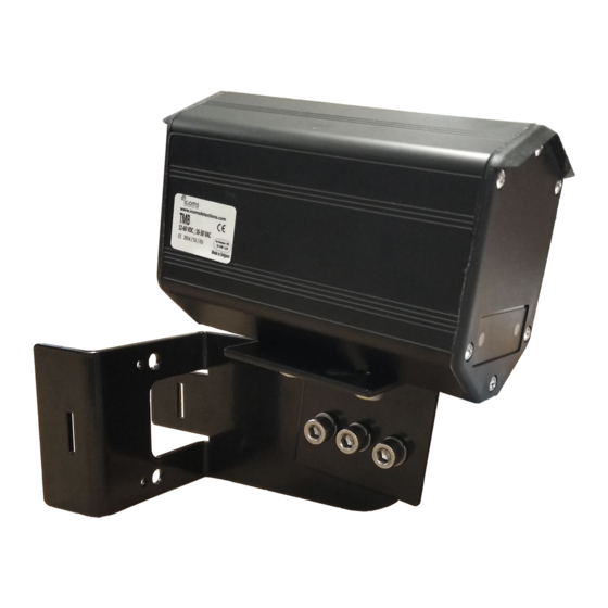
PRODUCT DESCRIPTION ELIVERY Some configurations may have a different cable and/or bracket. See tune up procedure for more details. Figure 1: delivery ABELS LOCATION DENTIFICATION LABEL ERIAL NUMBER Do not remove the labels ETTINGS Depending on the TMA configuration chosen, the settings are either done using 2 encoders with 16 positions each or using RS-232 serial communication. -
Page 5: Safety Precautions
SAFETY PRECAUTIONS Only skilled and instructed persons should carry out work with the radar product. Experience and knowledge about safety procedures in the following areas may be relevant: • Working with mains power • Working with modern electronic and electric equipment •... -
Page 6: Cabling
NC relay 2 WHITE / VIOLETT COM relay 1 NO relay 1 GREY YELLOW NC relay 1 Figure 3: TMA-122 LV and MV radar connector - Weipu GREEN COM relay 2 SP1712/P9 PINK ORANGE NO relay 2 (100-240 V AC) -
Page 7: Parameters Description
PRESENCE The TMA-122 detects the approaching moving and stopped vehicles at a distance of 10 or 15 m from the installation point. When a movement is detected in this area, the radar toggles the relay 1 and tracks the vehicle. It holds the relay activated as long as the vehicle is in the detection area, be the vehicle moving or not. -
Page 8: Configuration - Tune Up
CONFIGURATION – TUNE UP You can set different parameters through 2 encoders allowing 16 positions each. Encoder 1 Encoder 2 Figure 4: front face Figure 5: encoders & LEDs NCODER Besides red LED, at the left facing the housing Parameter Value Encoder position Distance “movement”... -
Page 9: Led Indicator
(O): max. 2 m • Distance between pole and the stop-line (D): min. 2 m SSEMBLY AND MOUNTING Bracket n°1 TMA-122 Bracket n°2 Figure 7: bracket elements 1. Set the appropriate parameter values with the encoders and place the sticker! -
Page 10: Key Points
2. Place the upper right screw to assemble bracket n°2 with bracket n° 1, with the upper right screw, allowing bracket nr 2 to rotate. Figure 8: bracket assembly 3. Fix the radar on bracket n°2 (see Figure 7). Pavement Figure 9: bracket position,... -
Page 11: Figure 12: Traffic Light Is On The Left Side From The Cars
Figure 12: Traffic light is on the left side from the cars Figure 13: view from behind - installation set when the traffic light is on the left side from the cars. • Installation on a horizontal pole: don’t tilt the radar (see p. 15). •... -
Page 12: Detection Zone
ETECTION ZONE Figure 16: stationary + movement zone (0-10 m) movement zone (0-60 m), H = 3,5 m, 45°tilt angle. This drawing shows the theoretical radar lobe for vehicles approaching around 50 kmh. Different “stop-line” length zones can be set: 10 or 15 m; the approaching zone length is about 60 m for a car and can be limited to 20 m. IMPACT OF THE TILT ANGLE Set the tilt angle to 10°... -
Page 13: Specific Installation Cases
Standard tilt angle of 45° Set the tilt angle to 10° away from the standard tilt angle in direction of the traffic lane. Figure 17: impact of the tilt angle SPECIFIC INSTALLATION CASES The installation position must be adapted when the road and/or the trajectory of the vehicles does not follow a straight line or when the radar is installed on a horizontal pole. -
Page 14: Best Practices
The road is here rapidly moving away from the detection axis (materialize by the orange line on Figure 18). The road widens and the stop line is not perpendicular to the lane: Figure 19: stop line at an angle On the Figure 19 sketch, you can observe that, according to the trajectory, the angle at which the vehicle enters the lobe might be 90°. -
Page 15: Installation On A Horizontal Pole
45 ° as for a roadside installation. H > 4,5 m Figure 21: horizontal pole – overview Figure 22 : TMA-122 on a horizontal pole, not tilted COUNTING FUNCTION The relay 1 toggles from [detection] -> [no detection] each time a vehicle passes the stop line. -
Page 16: Technical Features
Icoms Detections warrants its hardware products to be free from defects in workmanship and materials, under normal use and service, for a period of two (2) years from the date of dispatch from Icoms Detections premises, except for the batteries for which a warranty period of six (6) months applies. -
Page 17: Decommissioning
Icoms Detections will take care of the recycling for a sustainable end-of-life of the product. FURTHER INFORMATION EGAL NOTIFICATION Hereby, Icoms Detections declares that this TMA range of products is in compliance with the requirements and other relevant provisions of •...
Need help?
Do you have a question about the TMA-122 and is the answer not in the manual?
Questions and answers