
Related Manuals for icoms TMA-122


Summary of Contents for icoms TMA-122
-
Page 1: Table Of Contents
4 CABLING 5 TECHNICAL FEATURES 6 WARRANTY 7 FURTHER INFORMATION 7.1 L EGAL NOTIFICATION 7.2 V ERSION 7.3 T HE MANUFACTURER TMA-122 CONFIGURATION – TUNE UP 1 PARAMETERS DESCRIPTION 1.1 D “ ” ISTANCE MOVEMENT 1.2 D “ ” ISTANCE PRESENCE 1.3 M... -
Page 2: Encoder
4.3 IMPACT OF THE TILT ANGLE 5 COUNTING FUNCTION 6 WHAT TO TRY IF... FIGURE 1 : DELIVERY ............................3 FIGURE 2 : FRONT FACE FIGURE 3 : ENCODERS & LEDS ..................4 FIGURE 4 : FRONT FACE WITHOUT/WITH STICKER ....................4 FIGURE 5 : CONNECTOR WEIPU SP1712/P9 ...................... -
Page 3: Tma User Guide
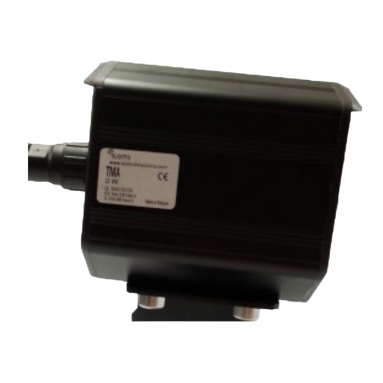
TMA User guide The TMA is a microwave sensor for traffic management (traffic data collection, intersection management, warnings, public lighting management), available in different configurations according to the applications. THEORY OF OPERATION 1. Unpack the unit and check the following items are in the box: A. -
Page 4: Settings
2.3 S ETTINGS You can set different parameters through 2 encoders allowing 16 positions each (see Tune Up procedure for further information). Figure 2 : front face Figure 3 : encoders & LEDs Once you have set the requested radar parameters, place the sticker on the front face to guarantee its water tightness. -
Page 5: Cabling
CABLING CAUTION : positive security/fail safe relays - contacts given for powered radar. 12-60 VDC – 10-30 VAC Power + 2 Power + 1 relay Power + 2 relays (NO) PIN nr Color relays* (NO/NC) (NO/NC) + RS232* + RS232* Power ~ (AC), + (DC) COM relay 2* BLUE... -
Page 6: Warranty
Icoms Detections warrants its hardware products to be free from defects in workmanship and materials, under normal use and service, for a period of two (2) years from the date of dispatch from Icoms Detections premises, except for the batteries for which a warranty period of six (6) months applies. -
Page 7: Tma-122 Configuration - Tune Up
MOVEMENT The TMA-122 detects the movement at a distance of about 60 meter from the installation point. It is possible to limit this distance to 20 m with encoder 1 (see Title 3.1.1, p. 8). When a movement is detected in this area, the radar toggles the relay 2. -
Page 8: Led Indicator
LED indicator 2.1 I N NORMAL OPERATION • The red LED shows the state of the relay 2. • The green LED shows the state of the relay 1. 2.2 W HEN THE SELF MONITORING DETECTS AN ERROR The two LEDs blink quickly (2 or 4 quick flashes followed by a 1 sec break, depending on the detected error). SETTINGS 3.1 ENCODERS See figures Figure 2and 3, p. -
Page 9: Installation Guide
(D): min. 2 m 4.2 A SSEMBLY AND MOUNTING Bracket n°1 TMA-122 Bracket n°2 Figure 6: bracket elements 1. Set the appropriate parameter values with the encoders and place the sticker! 2. Place the upper right screw to assemble bracket n°2 with bracket n°... -
Page 10: Key Points
5. Incline the radar bracket n°2 in direction to the pavement until the notch appears (Figure 9). Figure 9 : 45° tilt angle 6. Firmly tighten the screws. Figure 10: view from the front of the signal head: radar is leaning 4.2.1 Key points •... -
Page 11: Detection Zone
Pay attention that the signal head or other • obstacle is not obstructing the radar front face (Figure 13). Figure 13: pay attention to obstacles • Vehicles that enter within the stop-line zone (0-10m) from the side (perpendicular approach) may not be detected (Figure 14). To validate a measure, the radar needs: o to track an approaching movement at a minimum distance of 8 meters;... - Page 12 4.3 IMPACT OF THE TILT ANGLE Set the tilt angle to 10° away from the standard tilt angle in direction of the pavement. Standard tilt angle of 45° Set the tilt angle to 10° away from the standard tilt angle in direction of the traffic lane.
- Page 13 To keep in mind : The TMA-122 is not designed to detect on more than a single lane road (approaching traffic). Receding traffic within the radar lobe has no effect. To get the best result in terms of accuracy, the radar bracket (n°1) must be parallel to the approaching traffic direction.
Need help?
Do you have a question about the TMA-122 and is the answer not in the manual?
Questions and answers