
Related Manuals for Black Box MCX-G2-CONTROL-24


Summary of Contents for Black Box MCX-G2-CONTROL-24
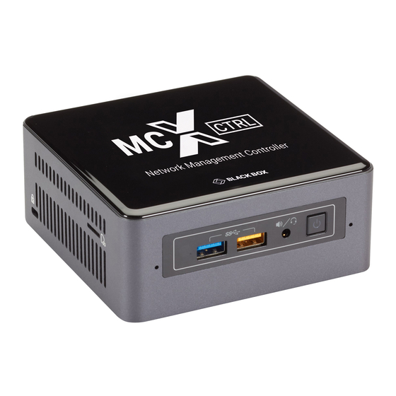
- Page 1 USER MANUAL MCX-G2-CONTROL-24, -48, -120, -250, -500, -UL MCX NETWORK MANAGEMENT CONTROLLER 24/7 TECHNICAL SUPPORT AT 1.877.877.2269 OR VISIT BLACKBOX.COM...
-
Page 2: Table Of Contents
NEED HELP? LEAVE THE TECH TO US LIVE 24/7 TABLE OF CONTENTS TECHNICAL SUPPORT 1.877.877.2269 CONTENTS 1. GLOBAL SETTINGS ...................................... 6 1.1 USERS ........................................... 6 1.1.1 ADD USER ..........................................6 1.1.2 EDIT USER ..........................................8 1.1.3 DELETE USER ........................................9 1.1.4 ACTIVE USERS ........................................10 1.2 PRESETS ........................................ - Page 3 NEED HELP? LEAVE THE TECH TO US LIVE 24/7 TABLE OF CONTENTS TECHNICAL SUPPORT 1.877.877.2269 2. DEVICE SETTINGS ..................................... 39 2.1 EDIT SETTINGS ......................................39 2.1.1 NAME ............................................ 39 2.1.2 GROUPS ..........................................40 2.1.3 NETWORK INTERFACE .....................................42 2.1.4 HDMI/DP INTERFACE ...................................... 44 2.1.5 HDMI INTERFACE (DECODER) ..................................
- Page 4 NEED HELP? LEAVE THE TECH TO US LIVE 24/7 TABLE OF CONTENTS TECHNICAL SUPPORT 1.877.877.2269 6. VIDEO WALL ........................................ 67 6.1 VIDEO WALL STANDARD ..................................68 6.2 VIDEO WALL ADVANCED ..................................70 7. MULTIVIEW ......................................... 73 7.1 MULTIVIEW LAYOUT ....................................74 7.2 MULTIVIEW LIVE ......................................
- Page 5 NEED HELP? LEAVE THE TECH TO US LIVE 24/7 TABLE OF CONTENTS TECHNICAL SUPPORT 1.877.877.2269 APPENDIX A. HOW TO VIDEO WALL WITH MULTIVIEW .......................... 91 APPENDIX B. SECURITY FEATURES ................................93 APPENDIX C. MULTICAST MANAGEMENT ............................... 95 APPENDIX D. USING GOOGLE ASSISTANT ............................... 96 APPENDIX E.
-
Page 6: Global Settings
NEED HELP? LEAVE THE TECH TO US LIVE 24/7 CHAPTER 1: GLOBAL SETTINGS TECHNICAL SUPPORT 1.877.877.2269 1. GLOBAL SETTINGS Here you will find all the global settings of the software. FIGURE 1-1. 1.1 USERS The system can be configured for user access control. Two levels of access are available, administrator and user. An administrator will have complete access, while a user is limited to the following areas: Š... - Page 7 NEED HELP? LEAVE THE TECH TO US LIVE 24/7 CHAPTER 1: GLOBAL SETTINGS TECHNICAL SUPPORT 1.877.877.2269 FIGURE 1-2. 1. Select Add 2. Select Level 3. Enter Username 4. Enter Password 5. Confirm Password 6. Select Groups 7. Select Functions 8. Click Save button 1.877.877.2269 BLACKBOX.COM...
-
Page 8: Edit User
NEED HELP? LEAVE THE TECH TO US LIVE 24/7 CHAPTER 1: GLOBAL SETTINGS TECHNICAL SUPPORT 1.877.877.2269 1.1.2 EDIT USER Here you can edit an existing users Username, Password, allocated groups, and functions. FIGURE 1-3. 1. Select Edit 2. Select User 3*. -
Page 9: Delete User
NEED HELP? LEAVE THE TECH TO US LIVE 24/7 CHAPTER 1: GLOBAL SETTINGS TECHNICAL SUPPORT 1.877.877.2269 1.1.3 DELETE USER Here you can delete an existing user from the system. FIGURE 1-4. 1. Select Delete 2. Select User 3. Click Delete button 1.877.877.2269 BLACKBOX.COM... -
Page 10: Active Users
NEED HELP? LEAVE THE TECH TO US LIVE 24/7 CHAPTER 1: GLOBAL SETTINGS TECHNICAL SUPPORT 1.877.877.2269 1.1.4 ACTIVE USERS Here you can see all the active users logged into the system and the time of their last activity. FIGURE 1-5. 1. - Page 11 NEED HELP? LEAVE THE TECH TO US LIVE 24/7 CHAPTER 1: GLOBAL SETTINGS TECHNICAL SUPPORT 1.877.877.2269 FIGURE 1-6. 1. Select New. 2. Enter a name. 3. Select a command or click Record button. 4. Fill in the required data or use the Assistant or click Stop if recording. 5.
-
Page 12: Edit Preset
NEED HELP? LEAVE THE TECH TO US LIVE 24/7 CHAPTER 1: GLOBAL SETTINGS TECHNICAL SUPPORT 1.877.877.2269 1.2.2 EDIT PRESET Here you can edit any existing preset by adding, deleting or changing control commands as required. FIGURE 1-7. 1. Select Edit 2. -
Page 13: Delete Preset
NEED HELP? LEAVE THE TECH TO US LIVE 24/7 CHAPTER 1: GLOBAL SETTINGS TECHNICAL SUPPORT 1.877.877.2269 1.2.3 DELETE PRESET Here you can delete any existing preset from the system. FIGURE 1-8. 1. Select Delete 2. Select Preset 3. Click Delete button 1.877.877.2269 BLACKBOX.COM... -
Page 14: Apply Preset
NEED HELP? LEAVE THE TECH TO US LIVE 24/7 CHAPTER 1: GLOBAL SETTINGS TECHNICAL SUPPORT 1.877.877.2269 1.2.4 APPLY PRESET Here you can apply any existing preset on the system. FIGURE 1-9. 1. Select Apply 2. Select Preset 3. Click Apply button 1.877.877.2269 BLACKBOX.COM... -
Page 15: Export Preset
NEED HELP? LEAVE THE TECH TO US LIVE 24/7 CHAPTER 1: GLOBAL SETTINGS TECHNICAL SUPPORT 1.877.877.2269 1.2.5 EXPORT PRESET Here you can export an existing preset on the system which can then be used as a backup or edited. The preset will be saved to your Downloads folder as an ini file like MyNewPreset.ini. -
Page 16: Import Preset
NEED HELP? LEAVE THE TECH TO US LIVE 24/7 CHAPTER 1: GLOBAL SETTINGS TECHNICAL SUPPORT 1.877.877.2269 1.2.6 IMPORT PRESET Here you can import a new preset into the system. (If updating an existing preset, the existing preset on the system will need to be deleted prior to importing.) FIGURE 1-11. -
Page 17: Preset Record
NEED HELP? LEAVE THE TECH TO US LIVE 24/7 CHAPTER 1: GLOBAL SETTINGS TECHNICAL SUPPORT 1.877.877.2269 5*. Rename preset 6. Click Save button 1.2.7 PRESET RECORD Selecting Record within Presets New or Presets Edit will record interactions from the UI directly into the selected preset. The following UI tabs will record interactions: Š... -
Page 18: Groups
NEED HELP? LEAVE THE TECH TO US LIVE 24/7 CHAPTER 1: GLOBAL SETTINGS TECHNICAL SUPPORT 1.877.877.2269 1.3 GROUPS System Encoders and Decoders can be arranged into various groups. These groups can then be individually controlled via the API or displayed in the UI. Here we manage the groups by adding, editing or deleting them. Once a group has been added to the system, the group can then be assigned to any or all Encoders and Decoders from the Device Settings tab. -
Page 19: Edit Group
NEED HELP? LEAVE THE TECH TO US LIVE 24/7 CHAPTER 1: GLOBAL SETTINGS TECHNICAL SUPPORT 1.877.877.2269 1.3.2 EDIT GROUP Here you can change the name of an existing group. FIGURE 1-15. 1. Select Edit 2. Select Group 3. Enter a new name 4. -
Page 20: Delete Group
NEED HELP? LEAVE THE TECH TO US LIVE 24/7 CHAPTER 1: GLOBAL SETTINGS TECHNICAL SUPPORT 1.877.877.2269 1.3.3 DELETE GROUP Here you can delete an existing group from the system. FIGURE 1-16. 1. Select Delete 2. Select Group 3. Click Delete 1.4 MULTICAST The Multicast section is used to initially set the system to use automatically assigned Multicast addresses within a specified range, or manually assign a range of Multicast addresses per stream type. - Page 21 NEED HELP? LEAVE THE TECH TO US LIVE 24/7 CHAPTER 1: GLOBAL SETTINGS TECHNICAL SUPPORT 1.877.877.2269 FIGURE 1-17. 1. Select AUTO 2. Enter desired addresses or select Default values 3. Click Save & Restart to apply the changes 1.877.877.2269 BLACKBOX.COM...
-
Page 22: Multicast Manual
NEED HELP? LEAVE THE TECH TO US LIVE 24/7 CHAPTER 1: GLOBAL SETTINGS TECHNICAL SUPPORT 1.877.877.2269 1.4.2 MULTICAST MANUAL Multicast Manual will initially assign static Multicast addresses to all Encoder stream types. Manual mode by default allocates a starting range address for the separate stream types in different subnets to ensure there is no possibility of mixed subscriptions whereby a Decoder might receive a video stream on an audio subscription. - Page 23 NEED HELP? LEAVE THE TECH TO US LIVE 24/7 CHAPTER 1: GLOBAL SETTINGS TECHNICAL SUPPORT 1.877.877.2269 FIGURE 1-19. Importing an HTTP API Security Key 1. Enter the Security Key. 2. Click Save button. FIGURE 1-20. 1.877.877.2269 BLACKBOX.COM...
-
Page 24: Tcp Security Key
NEED HELP? LEAVE THE TECH TO US LIVE 24/7 CHAPTER 1: GLOBAL SETTINGS TECHNICAL SUPPORT 1.877.877.2269 1.5.2 TCP SECURITY KEY The MCX Network Management Controller can be accessed via Telnet requests on TCP port 6980. To ensure security over the network a TCP security key can be passed with all such commands. -
Page 25: Analytics
NEED HELP? LEAVE THE TECH TO US LIVE 24/7 CHAPTER 1: GLOBAL SETTINGS TECHNICAL SUPPORT 1.877.877.2269 1.6 ANALYTICS Analytical data is constantly being stored on the system. By default data will be maintained for 1 month, but this can be changed up to 12 months. -
Page 26: Display Availability
NEED HELP? LEAVE THE TECH TO US LIVE 24/7 CHAPTER 1: GLOBAL SETTINGS TECHNICAL SUPPORT 1.877.877.2269 1.6.2 DISPLAY AVAILABILITY The Display Availability represents the time in hours a Decoder has a monitor connected. FIGURE 1-24. 1. Select Display Availability 2. Select Group 3. -
Page 27: Source Resolution
NEED HELP? LEAVE THE TECH TO US LIVE 24/7 CHAPTER 1: GLOBAL SETTINGS TECHNICAL SUPPORT 1.877.877.2269 1.6.3 SOURCE RESOLUTION The Source Resolution represents the combination of different resolutions used as a source. FIGURE 1-25. 1. Select Source Resolution 2. Select Group 3. -
Page 28: Source Count
NEED HELP? LEAVE THE TECH TO US LIVE 24/7 CHAPTER 1: GLOBAL SETTINGS TECHNICAL SUPPORT 1.877.877.2269 1.6.4 SOURCE COUNT The Source Count represents the number of times an Encoder detects a source available. FIGURE 1-26. 1. Select Source Count 2. Select Group 3. -
Page 29: Display Count
NEED HELP? LEAVE THE TECH TO US LIVE 24/7 CHAPTER 1: GLOBAL SETTINGS TECHNICAL SUPPORT 1.877.877.2269 1.6.5 DISPLAY COUNT The Display Count represents the number of times a Decoder detects a display available. FIGURE 1-27. 1. Select Display Count 2. Select Group 3. -
Page 30: Display Source Change
NEED HELP? LEAVE THE TECH TO US LIVE 24/7 CHAPTER 1: GLOBAL SETTINGS TECHNICAL SUPPORT 1.877.877.2269 1.6.6 DISPLAY SOURCE CHANGE The Display Source Change represents the number of times a Decoder has been switched to an Encoder. FIGURE 1-28. 1. Select Source Change 2. -
Page 31: Network Downtime
NEED HELP? LEAVE THE TECH TO US LIVE 24/7 CHAPTER 1: GLOBAL SETTINGS TECHNICAL SUPPORT 1.877.877.2269 1.6.7 NETWORK DOWNTIME The Network Downtime represents the time in hours a device is disconnected from the network. FIGURE 1-29. 1. Select Network Downtime 2. -
Page 32: Temperature
NEED HELP? LEAVE THE TECH TO US LIVE 24/7 CHAPTER 1: GLOBAL SETTINGS TECHNICAL SUPPORT 1.877.877.2269 1.6.8 TEMPERATURE The Temperature represents the operating temperature in either °C or °F of a device. FIGURE 1-30. 1. Select Temperature 2. Select Group 3. -
Page 33: Bandwidth
NEED HELP? LEAVE THE TECH TO US LIVE 24/7 CHAPTER 1: GLOBAL SETTINGS TECHNICAL SUPPORT 1.877.877.2269 1.6.9 BANDWIDTH The Bandwidth represents the total Encoder bandwidth in Gbps. FIGURE 1-31. 1. Select Bandwidth 2. Select Group 3. Select Start Date 4. Select End Date 5. -
Page 34: Scheduler
NEED HELP? LEAVE THE TECH TO US LIVE 24/7 CHAPTER 1: GLOBAL SETTINGS TECHNICAL SUPPORT 1.877.877.2269 1.7 SCHEDULER The Scheduler is used to apply presets at a particular time of a given day or system start. FIGURE 1-32. 1. Enter a name 2. -
Page 35: Permissions
NEED HELP? LEAVE THE TECH TO US LIVE 24/7 CHAPTER 1: GLOBAL SETTINGS TECHNICAL SUPPORT 1.877.877.2269 1.8 PERMISSIONS Permissions adds the ability to only allow certain Encoders to be joined with certain Decoders. Here Encoder1 is only allowed to be joined with Decoder1, and Encoder2 can be joined with any Decoder except for Decoder2. -
Page 36: Encryption
NEED HELP? LEAVE THE TECH TO US LIVE 24/7 CHAPTER 1: GLOBAL SETTINGS TECHNICAL SUPPORT 1.877.877.2269 1.9 ENCRYPTION Encryption can be applied to an Encoder’s HDMI AV network data. A user defined key is set and only Decoders with the same key will be able to decrypt the HDMI AV network data. -
Page 37: Notifications
NEED HELP? LEAVE THE TECH TO US LIVE 24/7 CHAPTER 1: GLOBAL SETTINGS TECHNICAL SUPPORT 1.877.877.2269 1.10 NOTIFICATIONS Notifications will send E-Mail alerts whenever a selected event occurs on the system. FIGURE 1-35. 1. Select events 2. Click Save button 1.877.877.2269 BLACKBOX.COM... -
Page 38: Email Settings
NEED HELP? LEAVE THE TECH TO US LIVE 24/7 CHAPTER 1: GLOBAL SETTINGS TECHNICAL SUPPORT 1.877.877.2269 1.10.1 EMAIL SETTINGS Here you configure the Email client to allow notification alerts to be sent from a specified Email account. The Test button sends a confirmation Email to confirm the settings are correct. -
Page 39: Device Settings
NEED HELP? LEAVE THE TECH TO US LIVE 24/7 CHAPTER 2: DEVICE SETTINGS TECHNICAL SUPPORT 1.877.877.2269 2. DEVICE SETTINGS This is where all the Encoders and Decoders are configured. Encoders and Decoders can be individually configured or all together taking advantage of exporting the csv formatted data and manipulating it as required before importing it back into the system. -
Page 40: Groups
NEED HELP? LEAVE THE TECH TO US LIVE 24/7 CHAPTER 2: DEVICE SETTINGS TECHNICAL SUPPORT 1.877.877.2269 FIGURE 2-2. 1. Enter Name or click Default button 2*. Select Update Alias 3. Click Save button 2.1.2 GROUPS Encoders and Decoders can be assigned to groups. These groups are created from the Global Settings tab. Once an Encoder or Decoder has been placed in a group, an alias name and an icon can be assigned to it. - Page 41 NEED HELP? LEAVE THE TECH TO US LIVE 24/7 CHAPTER 2: DEVICE SETTINGS TECHNICAL SUPPORT 1.877.877.2269 FIGURE 2-3. 1. Select Group 2. Enter an Alias 3. Select an icon 4. Click Save button 1.877.877.2269 BLACKBOX.COM...
-
Page 42: Network Interface
NEED HELP? LEAVE THE TECH TO US LIVE 24/7 CHAPTER 2: DEVICE SETTINGS TECHNICAL SUPPORT 1.877.877.2269 2.1.3 NETWORK INTERFACE To assign DHCP so the device is automatically assigned an IP address, select AUTO. FIGURE 2-4. 1. Select IP Mode AUTO 2. - Page 43 NEED HELP? LEAVE THE TECH TO US LIVE 24/7 CHAPTER 2: DEVICE SETTINGS TECHNICAL SUPPORT 1.877.877.2269 FIGURE 2-5. 1. Select IP Mode MANUAL 2. Enter an IP Address 3. Enter a Subnet 4. Enter a Gateway 5. Click Save button 1.877.877.2269 BLACKBOX.COM...
-
Page 44: Hdmi/Dp Interface
NEED HELP? LEAVE THE TECH TO US LIVE 24/7 CHAPTER 2: DEVICE SETTINGS TECHNICAL SUPPORT 1.877.877.2269 The function of the local 1 Gigabit network port can be enabled or disabled from here. 1. Select Enable or Disable 2. Click Save button 2.1.4 HDMI/DP INTERFACE Here you assign settings to the video input of an Encoder. -
Page 45: Hdmi Interface (Decoder)
NEED HELP? LEAVE THE TECH TO US LIVE 24/7 CHAPTER 2: DEVICE SETTINGS TECHNICAL SUPPORT 1.877.877.2269 * Select Browse to copy the EDID directly from any Decoder. Only Decoders with a Display connected will be shown 1. Select Input HDMI/DisplayPort/AUTO 2. -
Page 46: Multicast Management
NEED HELP? LEAVE THE TECH TO US LIVE 24/7 CHAPTER 2: DEVICE SETTINGS TECHNICAL SUPPORT 1.877.877.2269 1. The EDID can be saved to a file, sent directly to Encoders or copied to the clipboard. 2. The Decoder’s displays video mute status can be Enabled or Disabled. 3. -
Page 47: Analog Audio Interface
NEED HELP? LEAVE THE TECH TO US LIVE 24/7 CHAPTER 2: DEVICE SETTINGS TECHNICAL SUPPORT 1.877.877.2269 2.1.7 ANALOG AUDIO INTERFACE The 3.5-mm analog audio jack of an Encoder can work as either an input or an output. FIGURE 2-9. 1. Select either INPUT or OUTPUT 2. -
Page 48: Hdmi Audio Source
NEED HELP? LEAVE THE TECH TO US LIVE 24/7 CHAPTER 2: DEVICE SETTINGS TECHNICAL SUPPORT 1.877.877.2269 1. Select either ANALOG or HDMI 2. Click Save button 2.1.9 HDMI AUDIO SOURCE The audio of the HDMI can be either the original HDMI audio or the analog audio from an Encoder. FIGURE 2-11. -
Page 49: Export Settings
NEED HELP? LEAVE THE TECH TO US LIVE 24/7 CHAPTER 2: DEVICE SETTINGS TECHNICAL SUPPORT 1.877.877.2269 1. Select Baud rate 2. Select Data Bits 3. Select Stop Bits 4. Select Parity 5. Click Save button 2.2 EXPORT SETTINGS The current settings of all the Encoders and Decoders can be exported to a csv formatted file to be used as a configuration backup or be used to reconfigure the Encoders and Decoders by changing the required data and importing it back into the MCX Network Management Controller. -
Page 50: Import Settings
NEED HELP? LEAVE THE TECH TO US LIVE 24/7 CHAPTER 2: DEVICE SETTINGS TECHNICAL SUPPORT 1.877.877.2269 2.3 IMPORT SETTINGS The exported device settings file can be imported back into the system from here. Any device configuration changes made to the DeviceExport.csv will be applied once the file has been imported. -
Page 51: Status
NEED HELP? LEAVE THE TECH TO US LIVE 24/7 CHAPTER 3: STATUS TECHNICAL SUPPORT 1.877.877.2269 3. STATUS The Status tab contains information about how an Encoder or Decoder is currently functioning. Streams can also be stopped, started or frame rates halved to manage bandwidth. Encoders and Decoders can be filtered by groups to limit the number of devices being displayed. -
Page 52: Streams (Encoder)
NEED HELP? LEAVE THE TECH TO US LIVE 24/7 CHAPTER 3: STATUS TECHNICAL SUPPORT 1.877.877.2269 3.2.1 STREAMS (ENCODER) The Streams tab of an Encoder will show the status of all streams along with their multicast address. The resolution, frame rate and bandwidth of the video streams is also indicated. -
Page 53: Subscriptions (Decoder)
NEED HELP? LEAVE THE TECH TO US LIVE 24/7 CHAPTER 3: STATUS TECHNICAL SUPPORT 1.877.877.2269 3.2.3 SUBSCRIPTIONS (DECODER) The Subscriptions tab of a Decoder will show what multicast address is being used to receive data. It will also indicate from what Encoder it is receiving the streams and the video streams bandwidth. -
Page 54: Advanced
NEED HELP? LEAVE THE TECH TO US LIVE 24/7 CHAPTER 3: STATUS TECHNICAL SUPPORT 1.877.877.2269 3.2.4 ADVANCED The Advanced tab contains details of the device such as identification numbers, boot status along with the encryption status of the device. FIGURE 3-5. 3.3 EXPORT A JSON formatted file will export the complete status of the selected device. -
Page 55: Export Status Report
NEED HELP? LEAVE THE TECH TO US LIVE 24/7 CHAPTER 3: STATUS TECHNICAL SUPPORT 1.877.877.2269 3.4 EXPORT STATUS REPORT Export Status Report will save a csv formatted file with all the status details from this section. FIGURE 3-7. 1.877.877.2269 BLACKBOX.COM... -
Page 56: Group Health
NEED HELP? LEAVE THE TECH TO US LIVE 24/7 CHAPTER 3: STATUS TECHNICAL SUPPORT 1.877.877.2269 3.5 GROUP HEALTH Group Health will report the status of all the Encoders and Decoders in the selected group. If a group has a default preset associated with it, this can also be selected and applied to make sure there are no issues before the system is put into use. -
Page 57: Tools
NEED HELP? LEAVE THE TECH TO US LIVE 24/7 CHAPTER 4: TOOLS TECHNICAL SUPPORT 1.877.877.2269 4. TOOLS The Tools tab contains utilities to assist in the installation process and updating device firmware. FIGURE 4-1. 4.1 SEND SERIAL The Send Serial tab is used to test serial strings being sent from an Encoder or Decoder to 3rd party peripheral devices such as projectors. -
Page 58: Send Infrared
NEED HELP? LEAVE THE TECH TO US LIVE 24/7 CHAPTER 4: TOOLS TECHNICAL SUPPORT 1.877.877.2269 4. Select a terminator if required 5. Click Send button 4.2 SEND INFRARED The Send Infrared tab is used to test IR signals being sent from an Encoder or Decoder to 3rd party peripheral devices such as TV’s and DVD players. -
Page 59: Send Control Command
NEED HELP? LEAVE THE TECH TO US LIVE 24/7 CHAPTER 4: TOOLS TECHNICAL SUPPORT 1.877.877.2269 4.3 SEND CONTROL COMMAND The Send Control Command is used to send any of the API commands available to the system for testing purposes. FIGURE 4-4. 4.4 REBOOT DEVICE The Reboot Device tab is used to reboot the selected device(s). -
Page 60: Reset Device
NEED HELP? LEAVE THE TECH TO US LIVE 24/7 CHAPTER 4: TOOLS TECHNICAL SUPPORT 1.877.877.2269 4.6 RESET DEVICE The Reset Device tab is used to reset the selected device(s) back to factory defaults. FIGURE 4-6. 1. Select Device(s) 2. Click Reset button 1.877.877.2269 BLACKBOX.COM... -
Page 61: Update Device Firmware
NEED HELP? LEAVE THE TECH TO US LIVE 24/7 CHAPTER 4: TOOLS TECHNICAL SUPPORT 1.877.877.2269 4.6 UPDATE DEVICE FIRMWARE The Update Device Firmware tab is used to update the MCX or Icron USB firmware of Encoders and Decoders. Here you can also check for updated MCX firmware from the internet when the MCX Network Management Controller has access. - Page 62 NEED HELP? LEAVE THE TECH TO US LIVE 24/7 CHAPTER 4: TOOLS TECHNICAL SUPPORT 1.877.877.2269 FIGURE 4-8. FIGURE 4-9. 1. Click Discover button 2. Click a Network button to show network 1.877.877.2269 BLACKBOX.COM...
-
Page 63: Matrix
NEED HELP? LEAVE THE TECH TO US LIVE 24/7 CHAPTER 5: MATRIX TECHNICAL SUPPORT 1.877.877.2269 5. MATRIX The Matrix tab contains up to 6 individual matrix tabs for each of the signal types, Video, Digital Audio, Analog Audio, Serial, Infrared and USB. -
Page 64: Digital Audio
NEED HELP? LEAVE THE TECH TO US LIVE 24/7 CHAPTER 5: MATRIX TECHNICAL SUPPORT 1.877.877.2269 FIGURE 5-2. 5.3 DIGITAL AUDIO When independent routing of the Video and Digital Audio is required select the Separate Digital Audio Routing checkbox. Now the Video and Digital Audio will appear in separate independent matrix tabs. -
Page 65: Analog Audio
NEED HELP? LEAVE THE TECH TO US LIVE 24/7 CHAPTER 5: MATRIX TECHNICAL SUPPORT 1.877.877.2269 5.4 ANALOG AUDIO The matrix Analog Audio tab is intended for making analog audio joins between Encoders and Decoders. FIGURE 5-4. 5.5 SERIAL The matrix Serial tab is intended for making serial joins between Encoders and Decoders. Serial joins work on a one way principle in that the RX of the sender device is connected to the TX of the receiver device. -
Page 66: Infrared
NEED HELP? LEAVE THE TECH TO US LIVE 24/7 CHAPTER 5: MATRIX TECHNICAL SUPPORT 1.877.877.2269 5.6 INFRARED The matrix Infrared tab is intended for making infrared joins between Encoders and Decoders. Infrared joins work on a one-way principle in that the sender device is connected to the receiver device. This only creates a 1-way connection. For a 2-way (Bi-Directional) connection select the Bi-Directional checkbox before making joins. -
Page 67: Video Wall
NEED HELP? LEAVE THE TECH TO US LIVE 24/7 CHAPTER 6: VIDEO WALL TECHNICAL SUPPORT 1.877.877.2269 6. VIDEO WALL Video Wall configuration has two modes of operation, standard and advanced. Standard mode has simple bezel compensation when a uniform bezel size is used so only the display width and viewable width are required to calculate the required bezel compensation. -
Page 68: Video Wall Standard
NEED HELP? LEAVE THE TECH TO US LIVE 24/7 CHAPTER 6: VIDEO WALL TECHNICAL SUPPORT 1.877.877.2269 6.1 VIDEO WALL STANDARD FIGURE 6-2. 1. Select the group of Encoders and Decoders to be available. 2. Select a Group to be shown 3. - Page 69 NEED HELP? LEAVE THE TECH TO US LIVE 24/7 CHAPTER 6: VIDEO WALL TECHNICAL SUPPORT 1.877.877.2269 7. Select Aspect Ratio 8. Select switching Mode 9. Select Dynamic Preset 9.1 Select Compensation 9.2 Enter display width Enter viewable width 9.3 Enter display height Enter viewable height 10.
-
Page 70: Video Wall Advanced
NEED HELP? LEAVE THE TECH TO US LIVE 24/7 CHAPTER 6: VIDEO WALL TECHNICAL SUPPORT 1.877.877.2269 6.2 VIDEO WALL ADVANCED FIGURE 6-3. 1. Select a Group to be shown 2. Select Configuration Advanced 3. Select layout 4. Select source 5. Select resolution 6. - Page 71 NEED HELP? LEAVE THE TECH TO US LIVE 24/7 CHAPTER 6: VIDEO WALL TECHNICAL SUPPORT 1.877.877.2269 16. Select the resolution of the displays The cropped video area from the original source content will be scaled to a display resolution. So if the cropped area is only 960x540, in this case will be scaled to 1920x1080 for the display.
- Page 72 NEED HELP? LEAVE THE TECH TO US LIVE 24/7 CHAPTER 6: VIDEO WALL TECHNICAL SUPPORT 1.877.877.2269 In advanced mode, each individual display of the video wall can have separate bezel compensation applied when using a mix of display types. Click the display position and the displays bezel compensation window will popup. Here you can change the bezel sizes as required.
-
Page 73: Multiview
NEED HELP? LEAVE THE TECH TO US LIVE 24/7 CHAPTER 7: MULTIVIEW TECHNICAL SUPPORT 1.877.877.2269 7. MULTIVIEW The Multiview function has a lot of bandwidth considerations to take into account if both Encoder video streams are working. Keep in mind that an Encoder has two separate video streams. Stream 0 is the main stream used for normal video switching. This stream will automatically be slightly compressed with all streams greater than 9 Gbps. -
Page 74: Multiview Layout
NEED HELP? LEAVE THE TECH TO US LIVE 24/7 CHAPTER 7: MULTIVIEW TECHNICAL SUPPORT 1.877.877.2269 7.1 MULTIVIEW LAYOUT FIGURE 7-2. 1. Select 1 of the 42 predefined layouts. 2. Select the group of Encoders and Decoders to be available. 3. Select the required Decoder to display the layout. 4. -
Page 75: Multiview Live
NEED HELP? LEAVE THE TECH TO US LIVE 24/7 CHAPTER 7: MULTIVIEW TECHNICAL SUPPORT 1.877.877.2269 9. Save or apply the layout. The layout can be saved as a preset to be recalled via the “preset load” command or loaded back into the UI. FIGURE 7-3. -
Page 76: Multiview Presets
NEED HELP? LEAVE THE TECH TO US LIVE 24/7 CHAPTER 7: MULTIVIEW TECHNICAL SUPPORT 1.877.877.2269 7.4 MULTIVIEW PRESETS Multiview presets created and saved from the UI contain optional commands and logic that are present to manage system bandwidth and to provide a clean viewable experience. These optional commands and logic blocks can be removed or replaced with constant commands for known system conditions. - Page 77 NEED HELP? LEAVE THE TECH TO US LIVE 24/7 CHAPTER 7: MULTIVIEW TECHNICAL SUPPORT 1.877.877.2269 To reduce Encoder2 bandwidth workout if the main hdmi:0 stream can have half frame rate applied or if the original frame rate needs to be restored (optional) if(get video Encoder2 sm == PROGRESSIVE){ if(get video Encoder2 fps >...
- Page 78 NEED HELP? LEAVE THE TECH TO US LIVE 24/7 CHAPTER 7: MULTIVIEW TECHNICAL SUPPORT 1.877.877.2269 To reduce bandwidth from Encoder1 workout if we can use the main hdmi:0 stream instead of the sub stream hdmi:1 (optional, otherwise keep “join multi Encoder2 Decoder1 1 scaled MV_e1”) if(get video Encoder2 width == get window MV _ e1 1 width){ if(get video Encoder2 height == get window MV _ e1 1 height){ if(get video Encoder2 sm == PROGRESSIVE){...
- Page 79 NEED HELP? LEAVE THE TECH TO US LIVE 24/7 CHAPTER 7: MULTIVIEW TECHNICAL SUPPORT 1.877.877.2269 Turn off the Decoder video mute so the multiview can now be displayed (optional) set video _ mute Decoder2 false Remove any audio from the multiview Decoder (optional) leave audio _ d Decoder2 Here is the layout with all the optional commands and logic blocks removed.
-
Page 80: System Settings
NEED HELP? LEAVE THE TECH TO US LIVE 24/7 CHAPTER 8: SYSTEM SETTINGS TECHNICAL SUPPORT 1.877.877.2269 8. SYSTEM SETTINGS All the system level settings can be accessed by admin level users by clicking the gear icon on the top of the page. FIGURE 8-1. -
Page 81: Advanced Settings
NEED HELP? LEAVE THE TECH TO US LIVE 24/7 CHAPTER 8: SYSTEM SETTINGS TECHNICAL SUPPORT 1.877.877.2269 8.2 ADVANCED SETTINGS The Advanced Settings section contains the settings of the MCX Network Management Controller. FIGURE 8-3. 8.2.1 DEVICE DATA REFRESH Device Data Refresh is the time in milliseconds the MCX Network Management Controller requests information about the Encoders and Decoders. -
Page 82: Temperature
NEED HELP? LEAVE THE TECH TO US LIVE 24/7 CHAPTER 8: SYSTEM SETTINGS TECHNICAL SUPPORT 1.877.877.2269 8.2.5 TEMPERATURE Here you can select the system to display temperature of the Encoders and Decoders in either Celsius (°C) or Fahrenheit (°F). The default is Celsius (°C). -
Page 83: Import Settings
NEED HELP? LEAVE THE TECH TO US LIVE 24/7 CHAPTER 8: SYSTEM SETTINGS TECHNICAL SUPPORT 1.877.877.2269 8.4 IMPORT SETTINGS Use Import Settings to load an exported UIsettings.exp file which will restore the MCX Network Management Controllers settings. FIGURE 8-5. 8.5 SYSTEM CLOCK The MCX Network Management Controller contains a RTC (Real Time Clock) to maintain the correct time and date. -
Page 84: System Reboot
NEED HELP? LEAVE THE TECH TO US LIVE 24/7 CHAPTER 8: SYSTEM SETTINGS TECHNICAL SUPPORT 1.877.877.2269 8.6 SYSTEM REBOOT Here you can reboot the MCX Network Management Controller. It takes 60 seconds for the controller to Reboot. FIGURE 8-7. 8.7 SYSTEM LOGS The system keeps three (3) different log files, MCX, Software &... -
Page 85: System Log
NEED HELP? LEAVE THE TECH TO US LIVE 24/7 CHAPTER 8: SYSTEM SETTINGS TECHNICAL SUPPORT 1.877.877.2269 8.7.2 SYSTEM LOG A System Log contains all the control layer and UI logged information. FIGURE 8-8. 8.7.3 USB LOG A USB Log contains USB discovery and control logged information. FIGURE 8-9. -
Page 86: Check For Updates
NEED HELP? LEAVE THE TECH TO US LIVE 24/7 CHAPTER 8: SYSTEM SETTINGS TECHNICAL SUPPORT 1.877.877.2269 8.8 CHECK FOR UPDATES Check for Updates will contact an ftp server over the internet to obtain the latest releases. These system updates are separated into different sections depending on the type of data to be updated. -
Page 87: Import Updates
NEED HELP? LEAVE THE TECH TO US LIVE 24/7 CHAPTER 8: SYSTEM SETTINGS TECHNICAL SUPPORT 1.877.877.2269 8.9 IMPORT UPDATES When no internet access is available or a specific update is required the files will be provided to manually update the system. Select the type of update being performed by either selecting Software or MCX API. -
Page 88: License
The SDVoE MCX Management Controller will not operate without a valid license. When the MCX Network Management Controller is used for the first time you will be prompted to enter a License Key. If a License Key has already been issued it can be entered into the system from here. Contact Black Box for all licensing requirements. FIGURE 8-12. -
Page 89: Ui Overview
NEED HELP? LEAVE THE TECH TO US LIVE 24/7 CHAPTER 9: UI OVERVIEW TECHNICAL SUPPORT 1.877.877.2269 9. UI OVERVIEW Initially when the SDVoE MCX Network Management Controller is first used you will be prompted to enter a Registration Key obtained from your distributor. - Page 90 NEED HELP? LEAVE THE TECH TO US LIVE 24/7 CHAPTER 9: UI OVERVIEW TECHNICAL SUPPORT 1.877.877.2269 Once logged into the system, the Device Settings tab will be displayed by default. Users will automatically be logged out after 30 minues of inactivity. FIGURE 9-3.
-
Page 91: Appendix A. How To Video Wall With Multiview
NEED HELP? LEAVE THE TECH TO US LIVE 24/7 APPENDIX A: HOW TO VIDEO WALL WITH MULTIVIEW TECHNICAL SUPPORT 1.877.877.2269 APPENDIX A. HOW TO VIDEO WALL WITH MULTIVIEW Here is an explanation on how to create a Multiview layout on a video wall. To do this there are four (4) simple steps, make a physical HDMI connection between a dedicated Decoder and Encoder, create a Video Wall preset along with Multiview presets, and lastly execute the presets. - Page 92 NEED HELP? LEAVE THE TECH TO US LIVE 24/7 APPENDIX A: HOW TO VIDEO WALL WITH MULTIVIEW TECHNICAL SUPPORT 1.877.877.2269 2. Now create a Video Wall preset using the required display layout. For this example, a 2x2 Video Wall is used and the preset is saved as sample_VideoWall_2x2.
-
Page 93: Appendix B. Security Features
NEED HELP? LEAVE THE TECH TO US LIVE 24/7 APPENDIX B: SECURITY FEATURES TECHNICAL SUPPORT 1.877.877.2269 APPENDIX B. SECURITY FEATURES The Directory software has many security features built in which will be described in detail below. Some of these features are optional and can be enabled or disabled depending on your system security requirements. - Page 94 NEED HELP? LEAVE THE TECH TO US LIVE 24/7 APPENDIX B: SECURITY FEATURES TECHNICAL SUPPORT 1.877.877.2269 6. Permissions Permissions has the ability to only allow certain Encoders to be joined with certain Decoders. Example: Encoder1 is only allowed to be joined with Decoder1, and Encoder2 can be joined with any Decoder except for Decoder2.
-
Page 95: Appendix C. Multicast Management
NEED HELP? LEAVE THE TECH TO US LIVE 24/7 APPENDIX C: MULTICAST MANAGEMENT TECHNICAL SUPPORT 1.877.877.2269 APPENDIX C. MULTICAST MANAGEMENT Using the default MCX allocation of multicast addresses can lead to many issues which are all managed by the software when in multicast manual mode. -
Page 96: Appendix D. Using Google Assistant
NEED HELP? LEAVE THE TECH TO US LIVE 24/7 APPENDIX D: USING GOOGLE ASSISTANT TECHNICAL SUPPORT 1.877.877.2269 APPENDIX D. USING GOOGLE ASSISTANT The MCX Network Management Controller can be controlled with voice commands via Google Assistant. In this example we will run through the requirements to do so. -
Page 97: Appendix E. Frequently-Asked Questions (Faqs)
NEED HELP? LEAVE THE TECH TO US LIVE 24/7 APPENDIX E: FREQUENTLY-ASKED QUESTIONS (FAQS) TECHNICAL SUPPORT 1.877.877.2269 APPENDIX E. FREQUENTLY-ASKED QUESTIONS (FAQS) #1 Q: In Video Wall mode why do I see the video as a small image over a larger image? A: The source resolution has reduced since the crop settings were applied. - Page 98 NEED HELP? LEAVE THE TECH TO US LIVE 24/7 APPENDIX E: FREQUENTLY-ASKED QUESTIONS (FAQS) TECHNICAL SUPPORT 1.877.877.2269 #5 Q: What are the resolution limits of the scaler? A: The scaler can multiply or divide by eight (8). This applies horizontally and vertically. So for example a 480x270 image can be scaled up to 3840x2160 and a 240x135 image can be scaled up to 1920x1080.
- Page 99 NEED HELP? LEAVE THE TECH TO US LIVE 24/7 APPENDIX E: FREQUENTLY-ASKED QUESTIONS (FAQS) TECHNICAL SUPPORT 1.877.877.2269 #15 Q: What can cause a displays image to flicker? A: Video signals at 30Hz in sync modes with the frame rate set to half will cause the image to flicker. Make sure all 30Hz signals do not have the frame rate set to half.
-
Page 100: Disclaimer
F.1 DISCLAIMER Black Box Corporation shall not be liable for damages of any kind, including, but not limited to, punitive, consequential or cost of cover damages, resulting from any errors in the product information or specifications set forth in this document and Black Box Corporation may revise this document at any time without notice. - Page 101 NEED HELP? LEAVE THE TECH TO US LIVE 24/7 NOTES TECHNICAL SUPPORT 1.877.877.2269 1.877.877.2269 BLACKBOX.COM...
- Page 102 NEED HELP? LEAVE THE TECH TO US LIVE 24/7 NOTES TECHNICAL SUPPORT 1.877.877.2269 1.877.877.2269 BLACKBOX.COM...
- Page 103 NEED HELP? LEAVE THE TECH TO US LIVE 24/7 NOTES TECHNICAL SUPPORT 1.877.877.2269 1.877.877.2269 BLACKBOX.COM...
- Page 104 NEED HELP? LEAVE THE TECH TO US LIVE 24/7 TECHNICAL SUPPORT 1.877.877.2269 © COPYRIGHT 2020. BLACK BOX CORPORATION. ALL RIGHTS RESERVED. MCX-CONTROL_USER_REV1.PDF...
Need help?
Do you have a question about the MCX-G2-CONTROL-24 and is the answer not in the manual?
Questions and answers