Netio PowerCable REST 101 Series Manual
Hide thumbs
Also See for PowerCable REST 101 Series:
- Manual (78 pages) ,
- Quick installation manual (18 pages) ,
- Manual (79 pages)

Related Manuals for Netio PowerCable REST 101 Series


Summary of Contents for Netio PowerCable REST 101 Series
- Page 1 PowerCable 2PZ PowerCable 2KZ PowerCable REST 101x MANUAL FIRMWARE 3.2.7 and later 29.3.2023...
-
Page 2: Table Of Contents
5.3.4 M2M API Protocol – Telnet ............52 5.3.5 M2M API Protocol – Modbus/TCP ..........57 5.3.6 M2M API Protocol – MQTT-flex ............. 61 5.3.7 M2M API Protocol – Netio Push ............ 64 5.3.8 M2M API Protocol – SNMP ............66 Cloud ....................70 PAB .................... -
Page 3: Introduction
Introduction Thank you for purchasing this product of NETIO products a.s. Before using your product, please read this (MAN) and the included to avoid problems with User Manual Quick Installation Guide (QIG) incorrect installation or use. Caution: The product works with mains voltage. Mishandling may damage it or result in injury or death. -
Page 4: General Characteristics
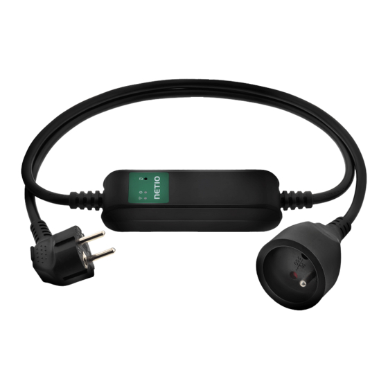
2 General characteristics WiFi interface: 802.11 b/g/n; 2.4GHz (secured / unsecured) / WEP, WPA, WPA2 AP mode for connecting the device to a local WiFi network (network selected from a list) Button to activate AP mode Output state can be toggled with the On/OFF button (press 3 times) ... - Page 5 Figure 1 – PowerCable 2PZ Figure 2 – PowerCable 2KZ Figure 3 – PowerCable REST 101x...
-
Page 6: Specifications
3 Specifications PowerCable 2PZ: 110/230 V~, 50-60Hz; 16A max PowerCable 2KZ: 110/230 V~, 50-60Hz; 16A max PowerCable 101E, 101F: 230V~; 50Hz; 16A Power PowerCable 101J: 230V~; 50Hz; 10A PowerCable 101S: 110/230V~; 60/50Hz; 10A PowerCable 101G: 230V~; 50Hz; 13A PowerCable 101B: 110V~; 60Hz; 15A PowerCable 2PZ: 110/230 V~, 50-60Hz;... - Page 7 The device is not designed to power appliances with a high inrush current. Do not connect several devices in series. The device is safe only when completely disconnected from the Caution electrical network. PowerCable REST 101x: The cable plug serves as the disconnection means and must be easily accessible.
- Page 8 PowerCable 2KZ...
- Page 9 PowerCable 2PZ...
- Page 10 PowerCable REST 101x NETIO products a.s. supplies the PowerCable REST 101x in several variants with different electrical plug/outlet types. Overview of models according to the electrical socket type Max. Max. Variant Output socket Input plug Voltage Model current load 101F...
- Page 11 Figure 6 - PowerCable REST 101J (CH –Type J) Figure 7 - PowerCable REST 101S (IEC-320 C13/C14) Figure 8 - PowerCable REST 101B (US –Type B)
- Page 12 Figure 9 - PowerCable REST 101G (UK –Type G)
-
Page 13: Features
NETIO products without energy metering support ZVS (Zero Voltage Switching) when switching 110/230V relay outputs. ZVS is sufficient relay switching technology for most load types, such as switching power supplies in IT solutions. - Page 14 <1% Quick WiFi connection setup (AP mode installation) NETIO PowerCable creates a WiFi network that you connect to with your PC or mobile phone. It then scans for WiFi networks in the area, and lets you choose from a list and type the password.
-
Page 15: Drawings
Drawings Figure 10 – PoweCable 2PZ top view... - Page 16 Figure 11 – PoweCable 2KZ top view...
- Page 17 Figure 12 – PoweCable xxx 101x side view Figure 13 – PoweCable xxx 101x top view...
-
Page 18: Device Description
Device description PowerCable 2PZ 1. 1x RJ45 LAN jack 2. RJ45 LEDs – device states (yellow and green) 3. TGL/RESET button 4. M2M activity LED (red) 5. Terminal blocks: Power input (L) and 2 power outputs Figure 14 – PoweCable 2PZ top view Figure 15 –... - Page 19 PowerCable 2KZ 1. 1x RJ45 LAN jack 2. RJ45 LEDs – device states (yellow and green) 3. TGL/RESET button 4. M2M activity LED (red) 5. DI (Digital Input) connectors with auxiliary 12V DC power 6. Terminal blocks: Power input (L) and 2 power outputs Figure 16 –...
- Page 20 PowerCable REST 101x 1. Status LED (yellow) 2. Output LED (green) 3. Button – to press, a thin object is needed (may be conductive) 4. Type plate – indicates the device model, electrical rating, maximum switching power and serial number (Figure 19) 5.
-
Page 21: Led And Button Functions
LED and button functions Button functions Controlling Press 3x within 1 to 5 seconds to switch the output. the output Press and hold for 10 seconds in the standard operating mode. AP mode Hold until the yellow LED (1) starts flashing rapidly. activation The AP mode is activated, making it possible to connect to the device and change the WiFi network to which it should connect. -
Page 22: Minimum System Requirements (For Configuration)
Minimum system requirements (for configuration) A device with an Internet browser (Firefox, Chrome, Safari, Microsoft Internet Explorer, Opera, Mozilla etc.) that has JavaScript and cookies enabled. Package contents NETIO PowerCable product Quick Installation Guide (QIG) Figure 21 – PoweCable REST 101x package... -
Page 23: Configuration And Control
WiFi is enabled only if Ethernet cable has not been connected yet! Plug the NETIO PowerCable into the electrical network. When the device is powered up for the first time, it enters the “AP mode” that enables basic configuration – selection of a WiFi network to which the device will connect (yellow LED flashes rapidly). - Page 24 Select your network in the list of detected networks and click “Next” (Figure 24). Enter the password for the selected WiFi network. You may also change the device name. If your network does not use DHCP, unselect this option and manually enter the IP address and other network parameters (Figure 26;...
- Page 25 A page with the connection result is displayed. If it shows “WiFi status: Connected“, check the network parameters and then click “Save&Connect” to save the configuration (Figure 27). The device then exits the AP mode, connects to the selected WiFi network, and displays a network configuration summary page (Figure 28).
-
Page 26: Detecting The Ip Address
If you connect to LAN or forgot the IP address, or if you have received a pre- configured device, you will need to find out its IP address. Use Windows based NETIO Discover utility, available for download at http://www.netio- products.com/en/software/netio-discover. -
Page 27: Static Ip
Enter the IP address into a web browser or the NETIO Mobile app and log in to the device. Note: If you can’t use MS Windows app, use NETIO Mobile2 App for iOS or Android. See details in the chapter... -
Page 28: Netio Mobile2
Searching NETIO devices in local network. Add devices from NETIO Cloud. You can use NETIO Mobile 2 application for Android or iOS to discover the local network and find NETIO devices there. Make sure your mobile device is connected to the same network as NETIO device. -
Page 29: Login To Device Web
Login to device web Figure 31 – PowerCable login dialog To log in, use admin admin (default login username / password) -
Page 30: Restoring Factory Defaults
Restoring factory defaults This operation deletes all user settings and restores the configuration to the factory defaults. It is useful when the device is in an unknown state or does not behave as described in this manual. Procedure: Turn off the PowerCable. Press and hold the button and power up the PowerCable. -
Page 31: Controlling The Output Manually
Controlling the output manually The output can be switched on/off (toggled) by pressing the button quickly 3 times in a row. Figure 33 – LED indication for manual output control... -
Page 32: Web Interface
5 Web interface Outputs In the left menu, click Outputs. A screen showing the PowerCable outputs appears. The outputs can be controlled directly with two buttons: Figure 34 – Controlling the output ON/OFF button controls the output directly. When the output is on, the button is green;... -
Page 33: Outputs - Energy Measurements
Reset button switches the output off and then back on. A confirmation is requested before the action is performed. The function is enabled only when the output is switched on. When the output is switched off, the Reset button is disabled. Click Reset to confirm the action or Cancel to cancel it. - Page 34 Load in watts [W] corresponds to the immediate current and voltage (P = U * I * TPF). It respects the direction – positive value if the connected device consume the energy or negative value if the connected device deliver the power back to the power grid (e.g. solar power system). Current in amps [A] shows the immediate current flowing through the output.
- Page 35 By default, the cumulative Energy consumption/delivery and Total Energy consumption/delivery are counted from the time the NETIO device was first powered on. To reset all Energy counters, go to the Settings > System tab and click the Reset Power Consumption Counters button (see Figure below).
-
Page 36: Outputs - General
5.1.2 Outputs - General Click the picture of the output to open detailed settings. General tab configures basic parameters for controlling the output. Figure 38 – General output configuration Output name is shown above the two control buttons to improve clarity. Short ON/OFF delay is an integer specifying, in milliseconds, the duration for the Short OFF (power cycling) and Short ON actions. -
Page 37: Outputs - Schedule
Reverse Energy NR in watt-hours (Wh / kWh) is the cumulative energy delivered back to grid since the device has been manufactured. This counter cannot be resetted. Only PowerPDU 4KS & PowerPDU 8QS shows this value. Click Save Changes to save the settings. To close the configuration dialog, click the symbol in the top right corner. -
Page 38: Inputs
Inputs PowerCable 2KZ only The PowerCable 2KZ has two DI’s (Digital Inputs) providing its status and S0 counter value. Connect DI pin with GND to initiate State ON (1). There is no LED indicating the DI state on the device. 5.2.1 DI (Digital Input) –... -
Page 39: Inputs - General
5.2.2 Inputs - General Click the picture of the input to open detailed settings. General tab configures basic parameters of the input. Figure 41 – General input configuration The Digital Input name can be set to identify specific digital input. Click Save Changes to save the settings. -
Page 40: Open Api: M2M Protocols
6 – ignore – ignores the action attribute and only respects the state attribute – only for XML and JSON Only one M2M protocol in addition to SNMP can be active at any time! Following M2M API Protocols cannot run in parallel to NETIO Cloud Connection: MQTT-flex Netio Push The notification message appears if you try to enable unsupported combination. -
Page 41: M2M Api Protocol - Xml Over Http
(output control). You may also fill in the username and password for this mode. Username Username for the respective access mode (Read-Only/ReadWrite). Note – this is unrelated to the username for accessing the NETIO 4x web administration interface. When left empty, the protocol will not require any authentication. Password... - Page 42 For an example of reading the output state using XML API, click the “Test XML API - Open XML API file (read password required)” link. After entering the username and password, you will receive an xml file with the NETIO device current state.
- Page 43 <Name>Power output 1</Name> <State>1</State> <Action>6</Action> <Delay>5000</Delay> <PowerFactor>0.99</PowerFactor> <Phase>0.14</Phase> <Load>2169</Load> <Current>9240</Current> <Energy>854863</Energy> <ReverseEnergy>0</ReverseEnergy> <EnergyNR>856469</EnergyNR> <ReverseEnergyNR>0</ReverseEnergyNR> </Output> <Output> <ID>2</ID> <Name>Power output 2</Name> <State>0</State> <Action>6</Action> <Delay>5000</Delay> <PowerFactor>1.00</PowerFactor> <Phase>0.00</Phase> <Load>0</Load> <Current>0</Current> <Energy>419136</Energy> <ReverseEnergy>0</ReverseEnergy> <EnergyNR>419136</EnergyNR> <ReverseEnergyNR>0</ReverseEnergyNR> </Output> </Outputs> <Inputs> <Input> <ID>1</ID> <Name>Input 1</Name> <State>1</State> <S0Counter>20729</S0Counter> </Input>...
- Page 44 <Enabled>false</Enabled> <Fail>false</Fail> <LastStatus>false</LastStatus> <Timestamp>0</Timestamp> </WdtItem> </Watchdogs> <Rules><Rule><Name>CR01_RULE</Name> <Enabled>false</Enabled> <Result>false</Result> </Rule> <Rule><Name>CR02_RULE</Name> <Enabled>false</Enabled> <Result>false</Result> </Rule> <Rule><Name>CR03_RULE</Name> <Enabled>false</Enabled> <Result>false</Result> </Rule> </Rules> </set:Root> The following example XML files for controlling the device can be downloaded directly from the web administration: • Set output 1 to ON •...
- Page 45 For the specifications of the M2M XML API protocol, visit the Support > Download section of our website and see the following document: XML - description of NETIO M2M API interface - PDF For more information and a practical demonstration of using the XML protocol with NETIO smart sockets, see the following Application Note: AN20...
-
Page 46: M2M Api Protocol - Json Over Http
Username Username for the respective access mode (Read-Only/ReadWrite). Note – this is unrelated to the username for accessing the NETIO device web administration. When left empty, the protocol will not require any authentication. - Page 47 For an example of reading the output state using JSON API, click the “Test JSON API: Open JSON API file (read password required)” link. After entering the username and password, you will receive a json file with the NETIO device current state.
- Page 48 {"Type":"RANGE","Name":"CR03_PAB","Enabled":false,"In":false} "Watchdogs":[ {"Name":"google_pinger","Enabled":false,"Fail":false,"LastStatus":fa lse,"Timestamp":0}, {"Name":"CR01_WDT","Enabled":false,"Fail":false,"LastStatus":false," Timestamp":0} "Rules":[ {"Name":"CR01_RULE","Enabled":false,"Result":false}, {"Name":"CR02_RULE","Enabled":false,"Result":false}, {"Name":"CR03_RULE","Enabled":false,"Result":false} The following example json files for controlling the device can be downloaded directly from the web administration: • Set output 1 to ON • Set output 1 to OFF • Toggle output 1 The Upload JSON file to the device button opens the following dialog for testing: Host –...
- Page 49 For more information about the M2M JSON API, visit the Support > Download section of our website and see the following document: JSON - description of NETIO M2M API interface - PDF For more information and a practical demonstration of using the JSON protocol with NETIO smart sockets, see the following Application Note: AN21...
-
Page 50: M2M Api Protocol - Url Api (Http Get)
5.3.3 M2M API Protocol – URL API (http get) Figure 46 –URL API protocol configuration Enable URL API Enables M2M URL API functions in the system. Port Read-only value. Indicates the port where the device currently listens for M2M URL API commands. This port is the same for all http based M2M API protocols and web administration and can be changed in Settings / System (chapter System). - Page 51 Download section of our website and see the following document: URL API - description of NETIO M2M API interface - PDF For more information and a practical demonstration of using the URL-API protocol with NETIO smart sockets, see the following Application Note:...
-
Page 52: M2M Api Protocol - Telnet
Username Username for the respective access mode (Read-Only/ReadWrite). Note – this is unrelated to the username for accessing the NETIO device web administration. When left empty, the protocol will not require any authentication. - Page 53 When the Telnet is enabled, other M2M protocols are disabled except SNMP after clicking Save changes. Start Telnet connection to a NETIO device IP address and its Telnet port When the connection is established, the NETIO device returns the following response and is ready to receive commands. Telnet welcome message 100 HELLO C9C410A0 - KSHELL V2.2...
- Page 54 Outputs are numbered from the left to right (1- 2-3-4). Control all outputs (1 and 4: ON, 2 and 3: OFF): port list 1001 Returns state of output: port list 1001 (outputs 1 and 4 are ON, 2 and 3 OFF) port <output>...
- Page 55 Command examples Switch power output 1 to ON: port 1 1 Switch power output 1 to OFF: port 1 0 Toggle power output 1: port 1 4 Status codes Status code Description 110 BYE Connection terminated by client after command quit 130 CONNECTION No command submitted for longer than 60...
- Page 56 Download section of our website and see the following document: Telnet - description of NETIO M2M API interface - PDF For more information and a practical demonstration of using the Modbus/TCP protocol with NETIO smart sockets, see the following Application Note:...
-
Page 57: M2M Api Protocol - Modbus/Tcp
5.3.5 M2M API Protocol – Modbus/TCP Figure 48 – Modbus/TCP protocol configuration Enable Modbus/TCP Enables M2M Modbus/TCP functions in the system. Port Specific port for Modbus/TCP only, range 1 – 65535. The device do NOT alerts you if you specify a port number that is already occupied. Last access IP Read-only value indicating the IP address from which the last Modbus/TCP command was received. - Page 58 Protocol properties • Modbus/TCP Unit ID is ignored. Can be anything 0 to 247 • Wire Address = Register Address – 1 Wire Address starts from 0 The Register Address starts from 1 Register Address is called “PLC based addressing” in some applications (Modbuss Poll for example ) Some utilities using the Wire Address...
- Page 59 0x04 uInt16 All outputs TPF [1/1000] 0x04 uInt16 1st output TPF [1/1000] 0x04 uInt16 2nd output TPF [1/1000] (value 9999=not measured) 0x04 Int16 All outputs Phase shift [1/10°] 0x04 Int16 1st output Phase shift [1/10°] 0x04 Int16 2nd output Phase shift [1/10°] (value 9999=not measured) 0x04 uInt16...
- Page 60 Modbus / TCP - description of NETIO M2M API interface - PDF For more information and a practical demonstration of using the Modbus/TCP protocol with NETIO smart sockets, see the following Application Note: AN27: Modbus/TCP with NETIO 4x – Control and measure LAN power sockets...
-
Page 61: M2M Api Protocol - Mqtt-Flex
When the MQTT-flex is enabled, other M2M protocols are disabled except SNMP after clicking Save changes. NETIO device uses json to define the MQTT-flex structure (MQTT-flex Config). Both subscribe and publish topics can be defined. Publish topics may include actions that initiate a transmission. - Page 62 MQTT-flex configuration example: "broker": { "clientid": "netio${DEVICE_SN}", "keepalive": 30, "password": "", "port": 1883, "protocol": "mqtt", "ssl": false, "type": "generic", "url": "broker.hivemq.com", "username": "" "publish": [ "events": [ "source": "OUTPUTS/1/STATE", "type": "change" "source": "OUTPUTS/2/STATE", "type": "change" "delta": 200, "source": "OUTPUTS/1/CURRENT", "type": "delta"...
- Page 63 You will find details and examples at our online resource center: https://wiki.netio-products.com/index.php?title=MQTT-flex For more information and a practical demonstration of using the MQTT protocol with NETIO smart sockets, see the following Application Note: AN40 Getting started with PowerCable MQTT-flex via HiveMQ MQTT broker to mobile App...
-
Page 64: M2M Api Protocol - Netio Push
M2M API Protocol – Netio Push Figure 50 –Netio Push protocol configuration Enable Netio Push Enables Netio Push functions in the system. Target host HTTP server: Defines the parameters of the target: - http / https to specify the protocol... - Page 65 60seconds). It means the output can be switched only when the TCP/IP connection is established. In default once every 60 seconds. If the response from Target host is error code 200 (OK) and the payload contains valid NETIO JSON structure with control command then the Output will be set accordingly. This way is possible to control device even if this is in private network behind NAT.
-
Page 66: M2M Api Protocol - Snmp
Also called the “community string” in SNMP. Similar to a username/password combination. Needed for reading information from NETIO device over SNMP. We recommend to use “pure” ASCII characters (that is, to avoid accented and special characters, such as @, & and so on, if possible). - Page 67 Security level (v3 only) authPriv / authNoPriv / noAuthNoPriv Auth protocol (v3 only) Authentication Protocol - An indication of whether messages sent on behalf of this user can be authenticated, and if so, the type of authentication protocol used. This can take one of the two values: SHA / MD5 Auth key (v3 only) Authentication protocol password - The (private) authentication key for use with the authentication protocol.
- Page 68 netioOutputPowerFactor.x.0 INTEGER Current power 1.3.6.1.4.1.47952.1.1.1.29.x.0 factor * 1000 netioOutputPhase.x.0 INTEGER 31683 [°] * 100 1.3.6.1.4.1.47952.1.1.1.30.x.0 netioOutputReverseEnergy.x.0 INTEGER 4747 [Wh] 1.3.6.1.4.1.47952.1.1.1.31.x.0 netioOutputEnergyNR.x.0 INTEGER 4093 [Wh] 1.3.6.1.4.1.47952.1.1.1.32.x.0 netioOutputReverseEnergyNR.x.0 INTEGER 6751 [Wh] 1.3.6.1.4.1.47952.1.1.1.33.x.0 netioVoltage.0 INTEGER 239100 Voltage in the 1.3.6.1.4.1.47952.1.2.1.0 power grid [mV] netioFrequency.0 INTEGER 49900...
- Page 69 Objects/OIDs). Please contact NETIO support in case of questions. For more information and a practical demonstration of using the SNMP protocol with NETIO smart sockets, see the following Application Note: SNMP management of 110/230V power outlets from the command line in Windows and Linux...
-
Page 70: Cloud
Cloud Netio Cloud is a service provided by NETIO Products a.s. and allow easy central remote control and monitoring of the NETIO devices. What can you do in NETIO Cloud? Output control On/Off switch. Reset button (Short Off for defined time). - Page 71 Connection to NETIO Cloud can be configured on Cloud tab. Figure 53 – Cloud configuration Enable NETIO Cloud Check to enable NETIO Cloud. Status Disconnected: Device not connected to Cloud Cloud connect faild…reconnecting: Device it trying to connect to Cloud.
- Page 72 Save Changes Saves the changes. Registration token Enter the registration token from NETIO Cloud web - shown when “ADD DEVICE” button used. Then press “Add device” button. Remove device If this device is connected to NETIO Cloud use this button to remove/disconnect it from NETIO Cloud.
-
Page 73: Pab
The PAB (Power Analysis Block) is Condition & Rules (C&R) function available for NETIO devices that periodically evaluates sets of conditions. Based on these conditions, subsequent Rules can be executed. These conditions can consist of one or more of following variables: Current [mA], Energy [Wh], Load [W], Power Factor, S0 pulses Several PAB’s can be configured and running simultaneously. -
Page 74: Watchdogs
Each Rule can perform several actions (Set Output, Short Off (restart) output, Toggle output or send Alarm state to the NETIO Cloud service. Based on this Alarm state can NETIO Cloud send email to defined recipient. All Watchdogs are listed in the JSON protocol with their current states. - Page 75 Figure 56 – Watchdogs configuration name The name of Watchdog configuration. Enable Watchdog Check to enable this Watchdog Watchdog config Watchdog configuration. Save Changes Saves the changes. Create Watchdog Opens a dialog to enter the new Watchdog configuration.
-
Page 76: Rules
Rules executed based on one PAB function (switch output if Current > 1000 mA + Send Alert to NETIO Cloud IF Current > 500 mA). One Rule can be executed based on combination of several PAB / WatchDog states. -
Page 77: Users
Users When several users use the PowerCable, it is advisable to assign them different accounts with the necessary privileges. In the left menu, select Users. Figure 58 – Adding and managing users Username The username. The PowerCable must always have an “admin” account with administrator privileges;... - Page 78 Opens a dialog to enter the parameters of a new user account. Save changes or Create User Saves the changes. Only an administrator or a user with the “manage users” privilege may change the passwords of other users. Note: User based account can be used for access to NETIO Mobile2 App.
-
Page 79: Schedules
Schedules can specify when should an output be switched on or when is an action valid. To manage schedules, select Schedules in the left menu. By default, NETIO PowerPDU contains one schedule: Always. To create a new schedule, click Create schedule. Specify the schedule name and set the intervals when the output should be switched on. Note... - Page 80 Figure 60 – Adding an interval with a precision to the second Deleting a schedule By deleting a schedule, all Schedulers for specific outputs with this schedule are automatically disabled. The states of the respective outputs are unchanged; however, from that moment on, the outputs are under manual control.
-
Page 81: Settings
5.10 Settings NETIO PowerCable 2KZ and PowerCable 2PZ can use the Ethernet connection (RJ45) or WiFi connection to network. When the Ethernet cable is connected the WiFi is completely turned off. When the Ethernet cable is disconnected then the WiFi turns automatically on. So Wi-Fi can be the main or only backup connection or not used. -
Page 82: Network Configuration
Network [Scan] From the menu, select a network to connect to. Press Scan to have PowerDIN 4PZ search for Wi-Fi networks in range. SSID Enter SSID if selected “Enter private SSID” in Network. Security Chose Secure/Open if selected “Enter private SSID” in Network. Password Password for connecting to the Wi-Fi network. - Page 83 (unsupported characters are replaced). Save Changes Saves the changes. Caution After changing the network configuration, it may be necessary to re-discover the NETIO device at its new address. The discovery procedure is described in section Detecting and configuring the IP address...
- Page 84 Ethernet Figure 63 – Network configuration - Ethernet MAC address Ethernet address of the Ethernet network adapter. Unique for each device. Also] corresponds to the NETIO device serial number. Status Connection status Use DHCP When selected, the device attempts to obtain network configuration from a DHCP server.
- Page 85 (unsupported characters are replaced). Save Changes Saves the changes. Caution After changing the network configuration, it may be necessary to re-discover the NETIO device at its new address. The discovery procedure is described in section Detecting and configuring the IP address...
-
Page 86: Date / Time
5.10.3 Date / Time In the Settings menu on the left, select Date/Time. Figure 64 – Date / time settings Use NTP server When selected, the device’s clock is periodically synchronized with a NTP server. If you do not have your own NTP server in your network, use e.g. -
Page 87: Firmware
Build date Creation date of the installed firmware version. Model Model designation. Revision Revision number. Firmware Package Click Browse to select a firmware file to install. Then click Install Firmware to start the installation. Firmware files are available at: https://www.netio-products.com/en/firmware-archive-netio... - Page 88 Go to the product page on our website (link below), select your product and scrool down the page. https://www.netio-products.com/en/products/all-products Figure 66 – WEB of NETIO products – Link to Firmware download Caution Before installing firmware, read carefully the instructions at our website, make sure that you are upgrading from the correct version, and follow the prescribed procedure.
-
Page 89: System
Currently installed firmware version and a link to the firmware download page. Device name Shown in NETIO Discover and under the device logo in the web administration (in the figure above: PowerCable-70 under the PowerCable Modbus logo in the top left corner) The device “Hostname”... - Page 90 affect the state of the output. Debug Log Adds a DebugLog section with diagnostic values to XML and JSON M2M API. Save Changes Saves the changes. Locate Identifies a particular device. When clicked, the yellow LED no. 1 starts flashing with pauses. Reset Power Consumption Resets the electricity consumption counters.
-
Page 91: Log
5.11 Log In the left menu, select Log. Figure 68 - Event log Refresh Reloads the log to show the most recent entries. Export to file Exports the log in the html format. Clear log Clears the log records. The log contains 40 most recent events only and is cleared when the device is restarted. - Page 92 Sources (types) of log entries: System Event generated by the system itself, e.g. WiFi reconnect WebApi Event related to a request from the web interface, e.g. User logged in M2M XML protocol JSON M2M JSON protocol M2M URL M2M URL API protocol Modbus M2M Modbus/TCP protocol MQTT...
-
Page 93: Declaration Of Conformity (Red Ce)
NETIO PowerCable 2KZ NETIO PowerCable 2PZ This declaration of conformity is issued under the sole responsibility of the manufacturer. Object of the declaration: “NETIO PowerCable 2KZ and PowerCable 2PZ controlled and monitored over the WiFi / LAN network”. RED: The product mentioned above to which this declaration relates is in conformity with the essential requirements and other relevant requirements of the Radio Equipment Directive (2014/53/EU). - Page 94 IEC320 C19/C20 This declaration of conformity is issued under the sole responsibility of the manufacturer. Object of the declaration: “Extension socket NETIO PowerCable 101x controlled and monitored over the WiFi / LAN network”. The object of the declaration described above is in conformity with the relevant Union harmonization legislation: ...
-
Page 95: Products Overview
7 Products overview WiFi / Power Input / Switched Metered Button(s) / Industrial Power-Up Power (RJ45) Ant. Output Type outputs outputs Inputs Output LED(s) features state ZCS, PowerPDU 4C (Linux) C14 / C13 RS232 110/230V / 10A 4 / 4 RS232 PowerPDU 4KS C14 / C13... -
Page 96: Product Features
8 Product features Scheduler Watchdog Local function function scripting PowerPDU 4C (Linux) Ping only PowerPDU 4KS Ping + Power C&R PowerPDU 4PS Ping C&R PowerPDU 8QS Ping + Power C&R PowerDIN 4PZ Ping + Power C&R PowerBOX 3Px (E,F,G) Ping C&R PowerBOX 4Kx (E,F,G) Ping + Power...
Need help?
Do you have a question about the PowerCable REST 101 Series and is the answer not in the manual?
Questions and answers