
Related Manuals for GESTRA URS 60


Summary of Contents for GESTRA URS 60
- Page 1 Safety Control Unit URS 60 URS 61 Installation & Operating Manual 819634-01 E n g l i s h...
-
Page 2: Table Of Contents
Safety control unit URS 61 ........................19 Functional elements and dimensions ......................20 Installing the URS 60/URS 61 safety control unit ..................21 Wiring diagram of the URS 60/URS 61 safety control unit ................22 Electrical connection .............................23 Bus line, cable length and cross-section ....................23 Connecting the 24V DC power supply .......................23... - Page 3 Emergency mode ............................33 Emergency mode for water level limiter systems ..................33 Taking out of service .............................34 Disposal .................................34 Returning decontaminated equipment ......................34 Declaration of Conformity; Standards and Directives ..................35 URS 60, URS 61 - Installation & Operating Manual - 819634-01...
-
Page 4: Content Of This Manual
The General Terms & Conditions of GESTRA AG apply. Scope of delivery/Product package 1 x Safety Control Unit URS 60 or URS 61 ■ 1 x Installation & Operating Manual ■ URS 60, URS 61 - Installation & Operating Manual - 819634-01... -
Page 5: How To Use This Manual
How to use this Manual This Installation & Operating Manual describes the correct use of URS 60 and URS 61 safety control units. It applies to all persons who integrate this equipment into control systems, install, bring into service, op- erate, maintain and dispose of this equipment. -
Page 6: Types Of Warning
CAUTION Warning of a situation that may result in minor or moderate injury. ATTENTION ATTENTION Warning of a situation that will result in damage to property or the environment. URS 60, URS 61 - Installation & Operating Manual - 819634-01... -
Page 7: Specialist Terms/Abbreviations
This type of electrically non-conductive connection makes sure the input and output circuits are electrically isolated from each other. SELV Safety Extra Low Voltage URS 60, URS 61 - Installation & Operating Manual - 819634-01... -
Page 8: Usage For The Intended Purpose
Usage for the intended purpose URS 60 and URS 61 safety control units can be used in combination with various safety sensors of types NRG 1..., NRG 2…, LRG 1… and TRV 5… to act as safety limiters for steam boiler and water boiler systems. -
Page 9: Admissible Accessories, Dependent On The Required Safety Integrity Level
Usage for the intended purpose Admissible accessories, dependent on the required safety integrity level URS 60 and URS 61 safety control units can be operated with the following system components: Safety Low-level Conductivity Temperature Operating Monitoring high-level limiter limiter limiter... -
Page 10: Improper Use
Electrician Refits Specialist staff Plant construction Fig. 2 Notes on product liability We the manufacturer cannot accept any liability for damages resulting from improper use of the equip- ment. URS 60, URS 61 - Installation & Operating Manual - 819634-01... -
Page 11: Functional Safety, Safety Integrity Level (Sil)
Performing an annual function test Check the function of the URS 60/URS 61 safety control unit at least once a year by triggering the safety circuit (T1 = 1 year). You can check the function either by pressing buttons 1 – 4 (see page 28) or by making the equipment actually exceed the limit values. -
Page 12: Reliability Data To En 61508
Fraction of undetected dangerous failures that have a beta = 2% common cause Fraction of detected dangerous failures that have a com- beta d = 1% mon cause Fig. 4 URS 60, URS 61 - Installation & Operating Manual - 819634-01... -
Page 13: Function
During a flushing process, the water level is not measured in the level pot for up to five minutes. When prompted by an SRL 6-60 monitoring unit, the URS 60/URS 61 safety control unit therefore bypasses the level electrode and monitors the maximum bypass time. -
Page 14: Possible Combinations Of Functions And Equipment
STL (STM) 2 with STL (STM) 3 with STL (STM) 4 with temperature transmitter temperature transmitter temperature transmitter temperature transmitter TRV 5-60 TRV 5-60 TRV 5-60 TRV 5-60 Fig. 5 URS 60, URS 61 - Installation & Operating Manual - 819634-01... - Page 15 > URS 61, channel 4 ■ Only one URS 60 and one URS 61 control unit may be used in the CAN bus network. Further combinations are possible and permitted. URS 60, URS 61 - Installation & Operating Manual - 819634-01...
-
Page 16: Technical Data
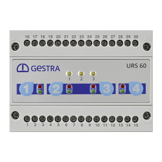
3 x yellow LEDs for indicating internal errors and external sensor errors ■ 1 x 10-pole code switch for setting the number of limiters, the delay and baud rate ■ URS 60, URS 61 - Installation & Operating Manual - 819634-01... - Page 17 ◆ Terminal box attachment: Mounting clip on support rail TH 35 (to EN 60715) ■ Installation in control cabinet (IP54) required ■ Weight Approx. 0.4 kg ■ URS 60, URS 61 - Installation & Operating Manual - 819634-01...
-
Page 18: Example Rating Plate/Identification Of Urs 60/Urs 61
0 Component type approval a Material number-serial number b Manufacturer c Component type approval d Disposal information The date of production is printed on the side of the equipment. URS 60, URS 61 - Installation & Operating Manual - 819634-01... -
Page 19: Factory Settings
Signalling delay: OFF ■ Configuration: ■ Operation e.g. with one NRG 1x-61 level electrode Code switch setting - sliding switch, white ■ 2 3 4 5 6 7 8 9 10 URS 60, URS 61 - Installation & Operating Manual - 819634-01... -
Page 20: Functional Elements And Dimensions
26. Front membrane with operating keys and LEDs, see page 28 Terminal box 1 12 13 14 15 Support rail TH 35 URS 60, URS 61 - Installation & Operating Manual - 819634-01... -
Page 21: Installing The Urs 60/Urs 61 Safety Control Unit
Installing the URS 60/URS 61 safety control unit The URS 60/URS 61 safety control units are clipped onto a TH 35 support rail in a control cabinet. DANGER There is a risk of electric shock during work on electrical systems. -
Page 22: Wiring Diagram Of The Urs 60/Urs 61 Safety Control Unit
CL = CAN Low S = shield 100 mA Fig. 9 The URS 61 control unit is connected as shown in the wiring diagram for the URS 60. URS 60, URS 61 - Installation & Operating Manual - 819634-01... -
Page 23: Electrical Connection
■ influences. Connecting the 24V DC power supply The URS 60/URS 61 safety control unit is supplied with 24V DC. ■ A safety power supply unit that delivers a Safety Extra Low Voltage (SELV) must be used to supply the ■... -
Page 24: Wiring Diagram Of Can Bus System
To activate this internal terminating resistor in the URS 60/URS 61 control units, insert a bridge between the terminals (“Option” and “CH”). Only one URS 60 and one URS 61 control unit may be used in the CAN bus network. ■... -
Page 25: Changing The Equipment Settings
Check that the plant is not carrying live voltage before commencing work. ■ You can change the factory settings of the URS 60/URS 61 safety control units at any time. Make changes before installing the safety control unit, when access is easier. -
Page 26: Configuring The Limiter Function
Changing the equipment settings The URS 60/URS 61 safety control units are designed for up to four limiter functions for monitoring water level, temperature and conductivity. You can connect NRG 1x-6x or NRG 26-61 level electrodes, the TRV 5-60 temperature transmitter and the LRG 1x-6x conductivity electrode. -
Page 27: Configuring The Delay Time And Baud Rate
* The delay is the factory-set relay OFF delay of 3 seconds (a 10 or 15-second delay is available as an option). When defining limiter functions 1 – 4, please also pay attention to the Installation & Operating Manuals of the relevant sensors. URS 60, URS 61 - Installation & Operating Manual - 819634-01... -
Page 28: Bringing Into Service - Starting, Operation, Alarm And Testing
The limiters must behave as if Signal LED 1, 2, 3 or 4 there were an alarm. lights up red The signal output is closed. The test ends. URS 60, URS 61 - Installation & Operating Manual - 819634-01... -
Page 29: Checking Installation And Function
(safety) circuit. This circuit must conform to the requirements of EN 50156. Faulty equipment jeopardises plant safety. If the URS 60/URS 61 control unit does not behave as described above in the “Alarm” and ■ “Test of limiters 1-4” tables, it may be faulty. -
Page 30: System Malfunctions
Disconnect all poles of the supply cable from the mains and secure so they cannot be ■ switched back on. Check that the plant is not carrying live voltage before commencing work. ■ Interrupting the CAN bus during operation triggers an alarm. ■ URS 60, URS 61 - Installation & Operating Manual - 819634-01... -
Page 31: Indication Of System Malfunctions
Installation & Operat- ing Manual. If the sensor itself does not indicate a fault, the ID has been assigned to another sensor in duplicate. URS 60, URS 61 - Installation & Operating Manual - 819634-01... - Page 32 Check the installation location of indicate overheating. flash green slowly. open without a delay. the relevant sensor. The relevant signal Insulate the sensor flange against output is closed. radiated heat. URS 60, URS 61 - Installation & Operating Manual - 819634-01...
-
Page 33: What To Do In The Event Of System Malfunctions
Emergency mode for water level limiter systems If the URS 60/URS 61 safety control unit works with two NRG 1x-60 level electrodes (low-level limiter system), if one electrode fails, the equipment can continue working with one level electrode in emergency mode, under constant supervision, in accordance with EN 12952 and EN 12953. -
Page 34: Taking Out Of Service
GESTRA AG. Such media include solid, liquid or gaseous substances, mixtures of these, or radiation. GESTRA AG can accept returned products only if accompanied by a completed and signed return note and also a completed and signed declaration of decontamination. -
Page 35: Declaration Of Conformity Standards And Directives
You can find details on the conformity of the equipment and the applicable standards and directives in the Declaration of Conformity and associated certificates. You can download the Declaration of Conformity from www.gestra.com and request relevant certifi- cates by writing to the following address: GESTRA AG Münchener Straße 77... - Page 36 You can find our authorised agents around the world at: www.gestra.com GESTRA AG Münchener Straße 77 UK Importer: 28215 Bremen GESTRA UK Ltd Germany Tel. +49 421 3503 0 Unit 1 Sopwith Park, Royce Close, +49 421 3503 393 West Portway Business Park, Andover, e-mail info@de.gestra.com...
Need help?
Do you have a question about the URS 60 and is the answer not in the manual?
Questions and answers