Table of Contents
Advertisement
Quick Links
Advertisement
Table of Contents

Summary of Contents for Level IPS-0008
- Page 1 IPS-0008 IP Power Switch User Manual Ver 1.0.1-0710...
- Page 2 Preface About this manual Congratulations on purchasing the IPS-0008. This user manual provides detailed descriptions of the hardware components and how to use it. Read this manual carefully and follow the instructions while using the IPS-0008. Copyright information No part of this manual, including the products and software described in...
- Page 3 Before plugging in the power cord of the device, make sure that the power source rating matches the power rating of the IPS-0008. Use a standard power cord when you connect any device to the outlets of IPS-0008.
-
Page 4: Table Of Contents
Table Content INTRODUCTION.......................1 1.1......................2 EATURES 1.2..................3 ACKAGE CONTENTS 1.3.................4 ARDWARE OMPONENTS 1.3.1. Front Panel ....................4 1.3.2. Status Indicator ..................6 1.3.3. Using the control buttons ................8 1.4.....................9 ANEL GETTING STARTED ....................11 2.1..................11 TTACHING THE FEET 2.2. -
Page 5: Introduction
The IPS-0008 comes with eight power outlets, each of which can be monitored and controlled through the console or web interfaces. You can also use the front panel to operate the power outlets. The IPS-0008 is also equipped with a console port for connecting an EMD... -
Page 6: Features
Active extended devices via digital outputs Monitor and manage connected devices and sensors remotely Control the IPS-0008 manually, or remotely through console or network Intelligent turn on/off devices based on event occurrence or planned schedule... -
Page 7: Package Contents
1.2. Package contents Make sure that your package has the following items. If any of items is missing or damaged, contact your nearest service center or vendor. 1. IPS-0008 IP Power Switch 2. Rack-mount Brackets 3. U-type Handle 4. U-type Handle Screws 5. -
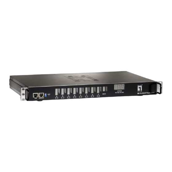
Page 8: Hardware Components
1.3. Hardware Components Take a moment to familiarize you with the IPS-0008 front and rear panels. The following sections provide descriptions about the front and rear panel components and how to use them. 1.3.1. Front Panel Component Description Output power status... - Page 9 Component Description Reset button Enables you to reset the IPS-0008 in case the system locks up. Operation mode DIP Sets the mode of operation for the switch IPS-0008. S1 off, S2 off: Normal operation (default mode) Serial (CONSOLE) port Enables you to configure the IPS-0008 using the serial port.
-
Page 10: Status Indicator
1.3.2. Status Indicator The front panel of the IPS-0008 has several LED indicators that provide information about the input and output power status. The following table describes these status indicators. Description Status Indicator Displays status of each power Output power status indicator (A ~... - Page 11 Status Indicator Displays input power consumed Input power consumption by the output devices connected indicator to the IPS-0008 outlets. The power consumption is displayed as a percentage value. Displays input voltage (Volts), Input power status indicator input current (Ampere), and frequency (Hz), sequentially on the 7-segment switching display.
-
Page 12: Using The Control Buttons
The control button has two modes of operation. Press the button repeatedly to switch between Remote Control mode and Power On/Off mode. When you press the control button, the IPS-0008 switches modes as follows: After switching modes, you need to press the control button again within 5 seconds to change the mode status. -
Page 13: Rear Panel
Power on/off mode Press the control button twice. The outlet power indicator starts flashing green. Now press control button again within 5 seconds and hold for more than 5 seconds. The outlet power indicator starts flashing green at a faster speed and then inverts its original state. For instance, if outlet power indicator is off (grey) before you press the control button, it turns on (green) after step 2, indicating that outlet power is turned on. - Page 14 Dry contact port Connect dry contact UPS that can be remotely managed through network card. This is currently not supported by the IPS-0008. Digital output Connect up to digital outputs that are normally open or normally closed.
-
Page 15: Getting Started
2. Getting Started This section provides information about setting up the IPS-0008, connecting power, and connecting devices to it before you start using it for power management. Read this section carefully to learn how to connect various devices to it. -
Page 16: Making Connections
2.3. Making Connections The IPS-0008 is a versatile product that can be connected to several different types of input and output devices. This makes it a useful tool for connecting devices to it and controlling their power on/off status through its user interface. - Page 17 Connect digital outputs to the digital I/O ports, and an EMD to the console port. To configure the IPS-0008, you can use the console or WAN port. Connect the IPS-0008 to a console and a WAN to enable its configuration through the console or browser menu.
-
Page 18: Connecting Input Power
2.4. Connecting Input Power The IPS-0008 has an IEC C20 power inlet for supplying and managing power for the output devices. Connect the power cord to the power inlet and plug the other end into a power outlet as shown:... -
Page 19: Connecting Output Devices
2.5. Connecting Output Devices The IPS-0008 has eight power outlets for connecting devices such as workstations, servers, and printers. Their power on/off status can be con- trolled manually as well as remotely through the LAN and Console ports. Connect the power connectors of the devices to each of the power... -
Page 20: Connecting Emd
An environmental monitored device that is connected to sensors for detecting temperature, humidity, water level, and so on can be connected to the IPS-0008 with the console port. The EMD can also be connected to alarms or indicators and controlled through the IPS-0008. -
Page 21: Connecting The Console
PC. Use the serial cable provided in your package to connect the COM port of your PC and the CONSOLE port of the IPS-0008 as shown. Refer to “Using the console menu” on page 16 to learn how to use the... -
Page 22: Connecting T O Awan
The IPS-0008 has a graphic user interface that allows you to control the device through a web browser. Connect the IPS-0008 to a free port on your router using an Ethernet cable as shown. You can then control the IPS-0008 from your PC, laptop, mobile phone, or PDA which is connected to the router network. -
Page 23: Using The Console Menu
3. Using the Console Menu The IPS-0008 is provided with a serial port that enables you to configure and control the system through your PC’s RS-232 serial (COM) port. Use the serial cable provided to connect the console port to your PC’s COM port as described in “Connecting the console”... - Page 24 Make sure that the Bits per second field is set to 9600. Click OK when done. 5. Press any key. The IPS-0008 Configuration Utility Main menu opens and you are prompted for a pass- word. Type the default password (admin) and press Enter to continue.
- Page 25 The main menu options are displayed.
-
Page 26: Navigating Through The Console Menu
To select a submenu, type the number corresponding to the submenu and press Enter. For example, to select the IPS-0008 Configuration menu, type 1 and press Enter. Submenus may have further nested menus which can also be accessed by typing the appropriate number. - Page 27 Email submenu for configuring the Email settings. This menu also provides the option under the control group submenu to enable input phase detection which allows the IPS-0008 to turn off outlet power if there is a phase mismatch. Outlets Control: This enables you to control all power outlets and configure each outlet's name, location, and other parameters.
-
Page 28: Setting The Ip Address
3.3. Setting the IP Address Follow these steps to set up the IP address of the IPS-0008: 1. Using the steps described under “Navigating through the console menu” on page 18, navigate to the System Group under the IPS-0008 Configuration menu. -
Page 29: Using The Web Interface
Start a web browser such as Internet Explorer from your host PC or laptop and enter the IP address of the IPS-0008 in the address bar. For details about setting the IP address of the system, see “Setting the IP address”... - Page 30 The main page shows a graphic representation of the IPS-0008 outlets and inputs status as described below: The left pane shows the various menus and submenus for the IPS-0008. Click any menu to display the menu options, expand the menu items, and modify the menu options as required.
-
Page 31: Modifying The Basic Settings
4.2.1. Setting the Date and Time Click Date and Time under System to view and modify the system date and time. This menu page displays the current IPS-0008 date and time. Select one of the options to configure the date and time by setting it manually, synchronizing with a computer’s time, or synchronizing it with... -
Page 32: Adding Users
4.2.2. Adding Users Click Multi-User under System to create a list of users who can access and control the IPS-0008. You can add users who can only view the IPS-0008 status or users who can change the outlet status of the IPS-0008. -
Page 33: Changing Event Alert Settings
4.2.3. Changing Event Alert Settings The IPS-0008 sends email or SNMP trap alerts to specified users when specific events occur. Use the following steps to set up these alerts Click Trap Receivers under System to set up a list of users or workstations who will be alerted with an SNMP trap message. - Page 34 Click Email Notification under Sys- tem to set up a list of up to 8 users who will be alerted with an email. Use this menu to specify the mail server, user account, DNS, and other information necessary to set up a mail server for sending mail alerts.
-
Page 35: Modifying Application Settings
H and digital out- puts. Hover your mouse cursor over the inlet or any of the outputs and click to configure them as follows: Inlet: Specify what action is taken by the IPS-0008 when the inlet voltage is not within limits. You can set which power outlets and digital outputs are to be turned on or off when the inlet voltage is not of acceptable value. -
Page 36: Setting Up A Schedule
4.3.2. Setting Up a Schedule Click Schedule under Power Management to see a list of schedules for turning power outlets on or off as desired. For instance, you may want to turn on all the servers and the administrator’s workstation every Mon- day morning. -
Page 37: Status
4.3.4. Configuration Click Configuration under Environment to configure the EMD connected to the IPS-0008. This menu enables you to set up the sensor names, high and low set points, calibration offsets for the sensors, as well as alarm names and normal conditions. You can also specify which EMD events and alarm conditions cause which power and digital outlets to be turned off. -
Page 39: Power Cycle
4.4. Power Cycle User can enable once power On/Off to restart the crash device for each of the eight outlet with Power Cycle button. This function will be worked when the status of outlet is power on. So, it connects to Power On/Off button of the Manual Control. -
Page 40: Appendix
Appendix Specifications Power Input/Output 110V model AC Input: IEC C20 inlet, 15 Amp, 100 ~ 125VAC, 50/60Hz AC Output: NEMA 5-15R outlet, 15 Amp, 100 ~ 125 VAC, 50/60Hz Load: 15 Amp for each outlet 220V model AC Input: IEC C20 inlet, 15 Amp, 200 ~ 250 VAC, 50/60Hz AC Output: IEC C13 outlet, 10 Amp, 200 ~ 250 VAC, 50/60Hz... -
Page 41: Error Codes
Input current sensor value abnormal Input source phase incorrect (see note below) Note: IPS-0008 detects the phase of the input source automatically. If the phase is opposite to that of the outlet phase, the outlet is turned off. The corresponding error code is displayed on the input power status indicator on the front panel with the error code and a message is displayed in a pop-window from your browser. -
Page 42: Regulatory Information
Regulatory information FCC Statement This device complies with Part 15 of the FCC rules. Operation is subject to the following conditions: This device may not cause harmful interference; and This device must accept any interference received, including interference that may cause undesired operation.