
Subscribe to Our Youtube Channel
Related Manuals for mercor mcr 0204


Summary of Contents for mercor mcr 0204
- Page 1 Technical and Operating Documentation User Instruction Manual mcr 0204 Smoke and Heat Exhaust Control Unit Nr dok: HO.19.01420.docx rew.: B z dn.: 2019-08-29...
-
Page 2: Table Of Contents
The above documents can be downloaded from the „MERCOR” S.A company website - www.mercor.com.pl Thank you for choosing the mcr 0204 control unit. We recommend you to read this User Manual with attention and to apply the recommendations therein. This will ensure smooth and reliable operation of the equipment. -
Page 3: Introduction
Smoke and Heat Exhaust Control Unit mcr 0204. User Instruction Manual. 2. INTRODUCTION The mcr 0204 control unit is used in smoke exhaust systems to control the operation of electrical actuators, and in particular vent actuators in mcr Prolight and mcr Prolight+ product range and in other mcr series products which require 24 V= voltage power, used for fire protection purposes. -
Page 4: Basic Information About The Unit
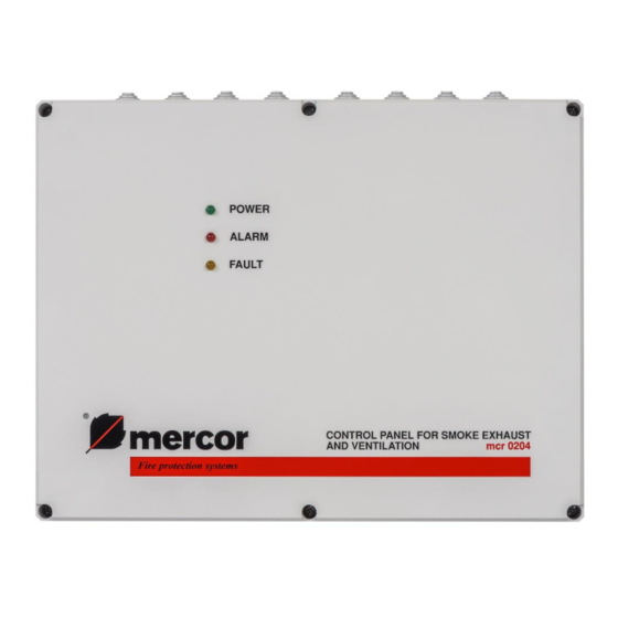
Smoke and Heat Exhaust Control Unit mcr 0204. User Instruction Manual. 3. BASIC INFORMATION ABOUT THE UNIT Fig. 1 Front panel of the unit. On the front panel there are diode indicators which inform the user about the unit's status. - Page 5 Smoke and Heat Exhaust Control Unit mcr 0204. User Instruction Manual. 13 12 14 Fig. 2 View of the unit's interior. On the unit module's PCB there is a RESET (1) pushbutton. It allows to cancel the alarm after the original cause of the alarm has been eliminated.
-
Page 6: Operation
BLINKING DEFECT The mcr 0204 control unit is a maintenance-free device. It requires uninterrupted 230 V mains power supply. Should there be power outage caused by mains failure, the installed batteries will ensure 72-hour emergency power supply. Any power outage exceeding 72 hours can result in permanent damage to the batteries. - Page 7 Smoke and Heat Exhaust Control Unit mcr 0204. User Instruction Manual. Pressing the button will always cause the smoke exhaust vent to close completely, while the opening time for the button depends upon the position of the SW1 switch in the unit module (Fig.
-
Page 8: Assembly And Start Up
Smoke and Heat Exhaust Control Unit mcr 0204. User Instruction Manual. When only the FAIL diode is on, the batteries have failed. In this case you should check battery connections and the condition of FS1 fuse (see page 6). When the FAIL diode blinks, this means that there is no mains power supply. In this case you should check the status of FS2 fuse (see page 6) and the 230 V voltage is present on the unit’s terminals. -
Page 9: Instruction Manual For Checking Connection And Performance Of The Mcr 0204 Control Unit
Smoke and Heat Exhaust Control Unit mcr 0204. User Instruction Manual. In order to check the operation of ventilation, the weather monitoring unit should be disconnected. The weather monitoring unit blocks ventilation for several minutes after the wind has ceased, and in the case of rain the sensor needs to get dry, which takes even more time. - Page 10 Smoke and Heat Exhaust Control Unit mcr 0204. User Instruction Manual. After checking the above points, make a record in all fields of the table below. Date of Result: Name and Name of “MERCOR” S.A’s control Working/not working surname enterprise:...
-
Page 11: Typical Connection Diagrams
LINE DEFECT RAIN BUTTON SENSOR Fig. 3 Typical configuration of smoke exhaust system with mcr 0204 unit. FP CU - fire protection control unit OCD - optical smoke sensor (KL731) RPO - mcr RPO-1 emergency pushbutton PM - assembly box ME - electrical actuator CP –... -
Page 12: Service And Maintenance
2. Checking the condition of electrical connections paying special attention to looseness and mechanical damage. In matters related to technical inspections, maintenance and repairs of devices, you can contact representatives of “MERCOR” S.A., tel. 58/341 42 45 during operating hours 8 - 16 (Mon-Fri), e-mail: serwis@mercor.com.pl. 9. WARRANTY TERMS AND CONDITIONS “MERCOR”... - Page 13 Any interference of unauthorized persons – except activities connected with normal operation of the equipment. 11. Moreover, in the cases specified in par. 10, “MERCOR” S.A. has no warranty obligations. As regards matters not regulated by these "Warranty terms and conditions", relevant regulations in the Civil Code, and in particular Art.
-
Page 14: Technical Specifications
Smoke and Heat Exhaust Control Unit mcr 0204. User Instruction Manual. 10. TECHNICAL SPECIFICATIONS Item Value Central type conventional Power supply voltage - basic 230 V (-15%, +10%) 50 Hz Rated power 100 VA Output voltage (power supply for actuators) 24 V=, max. -
Page 15: Declaration Of Performance
Smoke and Heat Exhaust Control Unit mcr 0204. User Instruction Manual. 11. DECLARATION OF PERFORMANCE Strona 15 z 16... -
Page 16: The Certificate Of Constancy Of Performance
Smoke and Heat Exhaust Control Unit mcr 0204. User Instruction Manual. 12. THE CERTIFICATE OF CONSTANCY OF PERFORMANCE Strona 16 z 16...
Need help?
Do you have a question about the mcr 0204 and is the answer not in the manual?
Questions and answers