Advertisement
Table of Contents
- 1 Table of Contents
- 2 Introduction
- 3 About the Mcr 9705 Control Unit
- 4 Exploitation
- 5 Assembly and Start up
- 6 Instruction Manual for Checking Connection and Performance of the Mcr 9705 Control Unit
- 7 Typical Connection Diagrams
- 8 Service and Maintenance
- 9 Warranty Terms and Conditions
- 10 Technical Specifications
- 11 The Declaration of Performance
- 12 European Certificate of Constancy of Performance
- Download this manual
Advertisement
Table of Contents

Related Manuals for mercor mcr 9705


Summary of Contents for mercor mcr 9705
- Page 1 Gdańsk, 09.10.2018 r. Technical and Operating Documentation User Instruction Manual Smoke and Heat Exhaust Control Unit mcr 9705 Nr dok: HO.18.00313 EN.doc rew.: B z dn.: 09.10.2018...
-
Page 2: Table Of Contents
Smoke and Heat Exhaust Control Unit mcr 9705 – User Instruction Manual Table of Contents 1. Introduction ......................3 2. About the mcr 9705 control unit ................4 3. Exploitation ......................8 4. Assembly and start up ..................12 5. Instruction manual for checking connection and performance of the mcr 9705 control unit ...................... -
Page 3: Introduction
Smoke and Heat Exhaust Control Unit mcr 9705 – User Instruction Manual 1. Introduction The mcr 9705 control unit is used in smoke exhaust systems to control the operation electrical actuators and in particular vent actuators in mcr PROLIGHT, mcr THERMOLIGHT, mcr ULTRA THERM, mcr LAM, mcr LAM-N,... -
Page 4: About The Mcr 9705 Control Unit
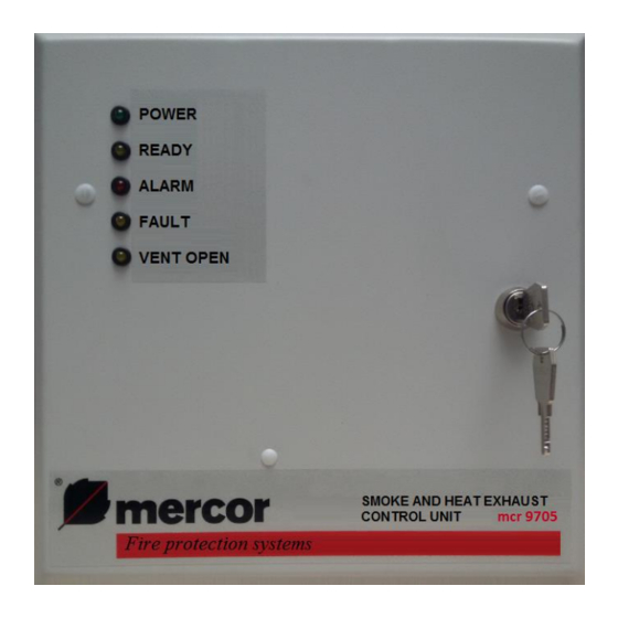
Smoke and Heat Exhaust Control Unit mcr 9705 – User Instruction Manual Closing of the vent after its emergency opening (deleting the alarm state) takes place after the cause of the alarm has been removed. Connecting of the mcr RPO-1 manual smoke exhaust pushbutton enables remote control panel operation (alarm enabling, alarm deleting and closing the vent after the alarm) and remote signalling of the system status (READY, FAULT, ALARM). - Page 5 Smoke and Heat Exhaust Control Unit mcr 9705 – User Instruction Manual Pic. 2 Inside view of the control unit’s door. On the inside of the control unit’s door there’s an audio alarm device (22) and the optical indicator board (23). Optical indicators are used for the system diagnostics:...
- Page 6 Smoke and Heat Exhaust Control Unit mcr 9705 – User Instruction Manual Pic. 3 Interior view of the control unit. At the bottom of the control unit module there is a multi-function button: No. Description Function in the alarm state - deleting the alarm and closing the...
- Page 7 Smoke and Heat Exhaust Control Unit mcr 9705 – User Instruction Manual Above the RESET pushbutton there are jumpers regulating the vent’s opening time in ventilation and entrance mode (combinations of settings can be found in Chap. 3.2): Description Function...
-
Page 8: Exploitation
BLINKS DISCONNECTION mcr 9705 is a maintenance-free device. It requires constant 230 V mains power supply. In case of power shortage caused by mains failure, the installed batteries will ensure 72-hour emergency power supply. Any power outage exceeding 72 hours can result in permanent damage of the batteries. - Page 9 Smoke and Heat Exhaust Control Unit mcr 9705 – User Instruction Manual on the jumpers H6 and H5 (Pic. 3 item 46 and item 47 table of settings below), SW1-5 ON Pressing the button once causes the vent to open for the time specified by appropriate settings on the H6 and H5 jumpers (Pic.
- Page 10 Smoke and Heat Exhaust Control Unit mcr 9705 – User Instruction Manual 3.3. Automatic weather monitoring unit If the system is equipped with wind and/or rain sensor, the sensor will prevent from opening of the smoke vents for non-emergency, daily ventilation in adverse weather conditions.
- Page 11 After alarm release from an external source (in/out) one first needs to delete the alarm in the device which initiated the response of the mcr 9705 control unit. Depending on the SW1-1 setting, there are 2 possible ways to delete the alarm:...
-
Page 12: Assembly And Start Up
In case of a system defect CALL THE SERVICE 3.8. Curtain control - Additional info For mcr PROSMOKE CE / CE1 curtains use the mcr 9705 control unit with the "curtain" option. Set the control unit into the curtain control mode (SW1-5 and SW1-6 ON). - Page 13 ON position. 16. Other devices activated only in the alarm state The mcr 9705 control unit has the option of connecting external devices supplied with 24 V = voltage, working in the alarm state, such as the SA-K7 optical- acoustic indicators.
-
Page 14: Instruction Manual For Checking Connection And Performance Of The Mcr 9705 Control Unit
Smoke and Heat Exhaust Control Unit mcr 9705 – User Instruction Manual - in the case of a device without a separate power source, connect the 2 wires (YnTKSY) with the power supply from terminal P19. An example of both variants of connection is shown in Diag. - Page 15 Smoke and Heat Exhaust Control Unit mcr 9705 – User Instruction Manual open the actuators line, the control panel in mode smoke exhaust), power supply damage (e.g. 230 V disconnect), battery detection (e.g. disconnect the batteries). Tests should be performed in a normal operating state for any potential damage.
-
Page 16: Typical Connection Diagrams
Smoke and Heat Exhaust Control Unit mcr 9705 – User Instruction Manual 6. Typical connection diagrams Diag. 1 Typical configuration of a smoke exhaust system equipped with the mcr 9705-5A control unit. Elements: CP - weather monitoring unit mcr P054 LT - ventilation pushbutton ŁNK - key switch for activating the "hatch"... - Page 17 Smoke and Heat Exhaust Control Unit mcr 9705 – User Instruction Manual Diag. 2 Typical connection of smoke curtain to control unit mcr 9705 (Execution for curtains mcr PROSMOKE CE/CE1). Elements: – optical smoke sensor (sensors should be connected according to advice of a manufacturer) –...
- Page 18 Smoke and Heat Exhaust Control Unit mcr 9705 – User Instruction Manual Diag. 3 Typical connection of smoke curtain mcr PROSMOKE FSv2 to control unit mcr 9705 (central unit in the mode “doors control”). Elements: - connection box MECU XL...
- Page 19 Smoke and Heat Exhaust Control Unit mcr 9705 – User Instruction Manual Strona 19 z 24...
-
Page 20: Service And Maintenance
“MERCOR” S.A. shall remove them within 21 days of the written notification, subject to paragraph 6. 3. “MERCOR” S.A. reserves the right to lengthen the repair time in the event of complicated repairs or those that require non-standard sub-assemblies [elements] or spare parts to be purchased. - Page 21 Any interference of unauthorized persons – except activities connected with normal operation of the equipment. 11. Moreover, in the cases specified in par. 10, “MERCOR” S.A. has no warranty obligations. As regards matters not regulated by these "Warranty terms and conditions", relevant regulations in the Civil Code, and in particular Art.
-
Page 22: Technical Specifications
Smoke and Heat Exhaust Control Unit mcr 9705 – User Instruction Manual 9. Technical specifications The data in the table below applies to the control panel with a single module: Item Value Base type: Control unit type conventional Power supply voltage – basic power supply ... -
Page 23: The Declaration Of Performance
Smoke and Heat Exhaust Control Unit mcr 9705 – User Instruction Manual 10. The Declaration of Performance 11. European Certificate of Constancy of Performance Strona 23 z 24... - Page 24 Smoke and Heat Exhaust Control Unit mcr 9705 – User Instruction Manual Strona 24 z 24...
Need help?
Do you have a question about the mcr 9705 and is the answer not in the manual?
Questions and answers