Advantech ICAM-500 Series User Manual
Icam-500 series
Hide thumbs
Also See for ICAM-500 Series:
- Startup manual (4 pages) ,
- Programming manual (64 pages) ,
- User manual (50 pages)
Table of Contents
Advertisement
Quick Links
Advertisement
Table of Contents

Related Manuals for Advantech ICAM-500 Series


Summary of Contents for Advantech ICAM-500 Series
- Page 1 User Manual ICAM-500 Series Integrated Industrial AI Camera...
- Page 2 No part of this manual may be reproduced, copied, translated, or transmitted in any form or by any means without the prior written permission of Advantech Co., Ltd. The information provided in this manual is intended to be accurate and reliable.
- Page 3 This product has passed the CE test for environmental specifications when shielded cables are used for external wiring. We recommend the use of shielded cables. This type of cable is available from Advantech. Please contact your local supplier for ordering information.
- Page 4 Technical Support and Assistance Visit the Advantech website at www.advantech.com/support to obtain the latest product information. Contact your distributor, sales representative, or Advantech's customer service center for technical support if you need additional assistance. Please have the following information ready before calling: –...
- Page 5 In accordance with IEC 704-1:1982 specifications, the sound pressure level at the operator's position does not exceed 70 dB (A). DISCLAIMER: These instructions are provided according to IEC 704-1 standards. Advantech disclaims all responsibility for the accuracy of any statements contained herein. ICAM-500 User Manual...
- Page 6 Der arbeitsplatzbezogene Schalldruckpegel nach DIN 45 635 Teil 1000 beträgt 70dB(A) oder weiger. Haftungsausschluss: Die Bedienungsanleitungen wurden entsprechend der IEC- 704-1 erstellt. Advantech lehnt jegliche Verantwortung für die Richtigkeit der in die- sem Zusammenhang getätigten Aussagen ab. ICAM-500 User Manual...
- Page 7 Safety Precaution - Static Electricity Follow these simple precautions to protect yourself from harm and the products from damage. To avoid electrical shock, always disconnect the power from the PC chassis before manual handling. Do not touch any components on the CPU card or other cards while the PC is powered on.
- Page 8 ICAM-500 User Manual viii...
-
Page 9: Table Of Contents
Chapter Hardware Installation ......9 Introduction ..................... 10 External Connector ................. 10 3.2.1 ICAM-500 Series External I/O Connector ........10 Figure 3.1 ICAM-500 series External I/O Connector ....10 3.2.2 PowerI/O ..................11 3.2.3 Ethernet/LAN ................13 3.2.4 Micro USB................... 14 3.2.5... - Page 10 Figure 4.12Platform Settings ............26 4.5.5 Hardware Trigger Mode.............. 27 4.5.6 Software Trigger Mode ............... 27 4.5.7 Continuous Mode................ 27 4.5.8 Set up the Digital I/O control............27 4.5.9 Trigger delay (Pin 16) ..............29 ICAM-500 camera parameters and SDK ..........29 Table 4.1: Camera parameters ..........
-
Page 11: Chapter 1 Product Overview
Chapter Product Overview... -
Page 12: Introduction
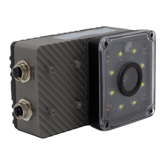
The preloaded, optimized Jetpack board support package seamlessly connect to AI cloud services.. Advantech ICAM-500 series is an all-in-one, compact and rug- ged industrial AI camera, and is ideal for a variety of Edge AI vision applications. - Page 13 – 12 mm variable focal length: FOV 40 x 29.3 mm @ 100 mm working distance FOV 364.5 x 263.7 @ 900 mm working distance – 16mm variable focal length: FOV 33.9 x 25.3 mm @ 100 mm working distance FOV 305.4 x 228.2 @ 900 mm working distance –...
-
Page 14: Environment Specification
Type Key of ICAM-500 Environment Specification Operating temperature: 0 ~ 40 °C Vibration during operation: 5 Grms EMC: CE, FCC ICAM-500 User Manual... -
Page 15: Chapter 2 Intended Use
Chapter Intended Use... -
Page 16: Overview Of Optical Functions
Focal length: 12mm Focal length: 16mm Figure 2.1 Field of view 2.1.2 Lens Movement ICAM-500 series equipped electronic lens motor and the followings are lens motor specification and behavior. Scenario Behavior and specification Action after Power lost Lens motor will stay in the last position before power lost. -
Page 17: Led Uniformity
2.1.4 LED Uniformity Figure 2.3 LEDs Uniformaity 2.1.5 LEDs Control Model ICAM-500 User Manual... - Page 18 ICAM-500 User Manual...
-
Page 19: Chapter 3 Hardware Installation
Chapter Hardware Installation... -
Page 20: Introduction
Disconnect all electrical components from the power supply when installing the ICAM-500. The following sections show the external connectors and pins assignment for appli- cations. External Connector 3.2.1 ICAM-500 Series External I/O Connector Figure 3.1 ICAM-500 series External I/O Connector ICAM-500 User Manual... -
Page 21: Poweri/O
3.2.2 PowerI/O Power, Digital I/O, and RS485 Connector Pigtail Description Remark Brown COM, RS232 TX No use Blue COM, RS232 RX No use White COM, RS485 D+ Green COM, RS485 D- Pink System power in GND Vin(-) Yellow System power in GND No use Vin(-) Black... - Page 22 Signal Connections: ICAM-500 series support sink type Digital I/O. Please follow the following instruction to wire the DI/O. Channel Num. Pin Num. Characteristics Voltage Current Dry contact Trigger Input Dry contact 10, 11 Sink type High: 28V Max. 100 mA...
-
Page 23: Ethernet/Lan
Supply voltage: 40Vdc Sink current: 0.2A max /Chanel 3.2.3 Ethernet/LAN Ethernet Connector (LAN) ICAM-500 series is equipped with one Ethernet controllers that are fully compliant with IEEE 802.3u 10/100/1000 Mbps CSMA/CD standards. The Ethernet port pro- vides a M12 connector. Signal MDI_0_P... -
Page 24: Micro Usb
3.2.4 Micro USB Signal Vbus (4.4-5.25V) 3.2.5 USB 3.1 USB type C connector ICAM-500 provides 1 USB type C interface connector which only for keyboard and mouse usage. Connect to USB storage will increase the power consumption and will heat the system. Please refer to the table below for pin assignments. Pin No. -
Page 25: Chapter 4 Getting Started
Chapter Getting Started... -
Page 26: Connection An Ethernet Cable
2. Use IP discover utility in Windows 10 OS host PC Follow the instruction to access ICAM-500 with host Linux OS PC. ipcfg configure iCam-500 network settings in Linux command line. Command location: /opt/advantech/sdk/bin/ipcfg Command Parameters: Help Show command parameters. - Page 27 Options ipcfg --nic-list List local network interfaces. ipcfg -C [cmd] Run commands (see Commands section) ipcfg -C [cmd] --remote-mac [MAC] Configure remote device with MAC address. ipcfg -C [cmd] --local-address [IP address] Configure specified NIC with the IP address. ipcfg -C [cmd] --local-device [dev_name] Configure device named [dev_name].
- Page 28 The IP address of ICAM-500 can be modified via discover utility. Discover utility is an ipconfig which is an application tool to access network configura- tion of ICAM-500 in LAN. Please download the IP discover utility from Advantech website (https://www.advantech.com/search/?q=ICAM-500&st=support) and decom-...
-
Page 29: Start Acquisition
Start Acquisition Follow the instruction of web UI to select the “New Project” bottom to create a new project for ICAM-500 configuration. Figure 4.3 Add new project Fill in the content of new project, output resolution and select the trigger mode then confirm to save project, select the project just created, click the “next”... - Page 30 Image save function only works on continuous mode and only can save the image in ICAM-500. The image will be saved in /opt/advantech/web/temp_- folder/project/{projectName}/images. Figure 4.5 Content of new project Figure 4.6 Start acquisition ICAM-500 User Manual...
-
Page 31: Configure Icam-500 Camera
Configure ICAM-500 Camera All the camera functions are listed on the right hand side of UI. ICAM-500 provides camera setting, generic setting, ROI setting, I/O setting and LED indicator settings. In addition to using web browser to configure the ICAM-500, Python based example and APIs provide more flexible way to configure and integrate the ICAM-500. -
Page 32: Camera Acquisition Setting
4.5.1 Camera Acquisition Setting This section shows camera acquisition settings that included trigger mode, lens focus settings and PWM LEDs lighting settings. The exposure time will affect the Continuous mode Figure 4.8 Camera Acquisition Setting ICAM-500 User Manual... -
Page 33: Isp Settings
4.5.2 ISP Settings This section shows ISP settings. Brightness The camera brightness refers to the brightness when the camera adjusts image under Auto exposure mode, or Auto Gain mode. You can set brightness as shown below. Set Brightness according to actual demand, and its range is from 0 to 255. - Page 34 Color HUE To shifts the color of image color via the color HUE controls. HUE only works on YUV and RGB format. The range of saturation is from 0 to 255. Color Saturation To changes the colorfulness of image color via the color saturation controls. Satura- tion only works on YUV and RGB format.
- Page 35 Find corresponding R/G/B channel in Balance Ratio Selector. Here we take Green as an example. Find camera’s R/G/B value. Take Green as correction standard, and manually adjust other two channels (R channel and B channel) to let these three channels have same value. **** Here we take Green as an example.
-
Page 36: Roi Setting & Output
4.5.3 ROI Setting & Output This section shows how to set the image resolution of camera. There are four types resolution for setting. Figure 4.11 ROI Setting & Output 4.5.4 Platform Settings This section shows the setting of LED indicators, digital input and digital output. Figure 4.12 Platform Settings ICAM-500 User Manual... -
Page 37: Hardware Trigger Mode
4.5.5 Hardware Trigger Mode In hardware trigger mode, the digital output pin of ICAM-500 must be connected to the trigger input (pin 16) of the cameras, and the camera will begin the process of exposing and reading out a frame, below are the operation procedures: Wire trigger input (pin 16) Configure the camera in hardware trigger mode. - Page 38 4.5.8.1 Digital Input and trigger input There are two digital inputs (Pin 8,9), support debouncer features. The debouncer feature identifies the valid and invalid input signals via setting the debouncer value (the minimum period of time for the valid signal). In this way, the circuit will only respond to the signal that the pulse width is greater than debouncer value trigger in: default setting debouncer 50 us.
-
Page 39: Trigger Delay (Pin 16)
4.5.9 Trigger delay (Pin 16) The Trigger delay allows user to add a delay between the receipt of a hardware trig- ger signal and the moment the trigger becomes active. ICAM-500 camera parameters and SDK All the information of the APIs and example please refer to the programming guide. Table 4.1: Camera parameters Function Name Parameters... -
Page 40: Project Management
Gain Auto Gain Mode/Intensity Range(0~24) Platform Settings DI 0/1 Debounce time Edge Trigger (Rising) DO 0/1 Output High I/O Setting Output Low Programming Mode Direct Output Reverse on/off Delay time (ms) Green User-defined LED Orange Yellow Project management ICAM-500 allow user to save camera setting as project and provides auto-run, import and export function. -
Page 41: Project Import & Export
4.7.2 Project import & export ICAM-500 provides the project import and export function. 4.7.2.1 Project import Click the project import icon and upload the selected project to import. Figure 4.14 Project import 4.7.3 Project export Click the project export icon and export the selected project to download folder. Figure 4.15 Project export ICAM-500 User Manual... - Page 42 ICAM-500 User Manual...
-
Page 43: Troubleshooting
Chapter Troubleshooting... -
Page 44: Connection For Keyboard, Mouse And Display
Please setup the ICAM-500 with following instruction to operating ICAM-500 in local for troubleshooting, if user have problem to connect the ICAM-500 via host PC. Con- tact Advantech FAE for technical support If ICAM-500 still can’t be boot up and acqui- sition after reset up the ICAM-500. - Page 45 Copy BSP file (Ex: ICAM-500_Nano_4.5.1_1.1.10.5_MassFlash.tbz2) to Host Enter following command on Host PC to un-tar BSP image file: tar –vxjf ICAM-500_Nano_4.5.1_1.1.10.5_MassFlash.tbz2 Press and hold the Reset and Recovery buttons on the ICAM-500 at the same time. Release the Reset button first. Release the Recovery button after waiting for 3 seconds.
-
Page 46: Expand Storage Space With Sd Card
Expand storage space with SD card If you have insufficient storage space to deal with, please ask your local FAE/AE for an SD card expansion tool. Please prepare an SD card with a capacity of at least 32GB, 64GB is better. Insert the SD card into the ICAM-500 then enter the “sdcard-expansion-tool.sh”... - Page 47 ICAM-500 User Manual...
- Page 48 No part of this publication may be reproduced in any form or by any means, electronic, photocopying, recording or otherwise, without prior written permis- sion of the publisher. All brand and product names are trademarks or registered trademarks of their respective companies. © Advantech Co., Ltd. 2022...