Table of Contents
Advertisement
Quick Links
Advertisement
Table of Contents

Related Manuals for Advantech ICAM-7000 Series


Summary of Contents for Advantech ICAM-7000 Series
- Page 1 User Manual ICAM-7000 Series fully integrated smart camera...
- Page 2 No part of this manual may be reproduced, copied, translated or transmitted in any form or by any means without the prior written permission of Advantech Co., Ltd. Information provided in this manual is intended to be accurate and reliable. How- ever, Advantech Co., Ltd.
- Page 3 This product has passed the CE test for environmental specifications when shielded cables are used for external wiring. We recommend the use of shielded cables. This kind of cable is available from Advantech. Please contact your local supplier for ordering information.
- Page 4 Technical Support and Assistance Visit the Advantech web site at www.advantech.com/support where you can find the latest information about the product. Contact your distributor, sales representative, or Advantech's customer service center for technical support if you need additional assistance. Please have the following information ready before you call: –...
- Page 5 The sound pressure level at the operator's position according to IEC 704-1:1982 is no more than 70 dB (A). DISCLAIMER: This set of instructions is given according to IEC 704-1. Advantech disclaims all responsibility for the accuracy of any statements contained herein.
- Page 6 Der arbeitsplatzbezogene Schalldruckpegel nach DIN 45 635 Teil 1000 beträgt 70dB(A) oder weiger. Haftungsausschluss: Die Bedienungsanleitungen wurden entsprechend der IEC- 704-1 erstellt. Advantech lehnt jegliche Verantwortung für die Richtigkeit der in die- sem Zusammenhang getätigten Aussagen ab. ICAM-7000 User Manual...
- Page 7 Safety Precaution - Static Electricity Follow these simple precautions to protect yourself from harm and the products from damage. To avoid electrical shock, always disconnect the power from your PC chassis before you work on it. Don't touch any components on the CPU card or other cards while the PC is on.
- Page 8 ICAM-7000 User Manual viii...
-
Page 9: Table Of Contents
Environment Specification................. 4 Chapter Installation........5 Introduction ....................6 External connector ..................6 2.2.1 ICAM-7000 series External I/O Connector........6 Chapter Getting started ........11 Connection a USB type C adaptor/cable ..........12 Connection an Ethernet cable..............12 Connection a Power, D I/O and PWM cable........... 12 Install the lenses .................. - Page 10 ICAM-7000 User Manual...
-
Page 11: Chapter 1 Product Overview
Chapter Product Overview... -
Page 12: Introduction
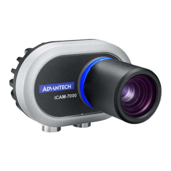
Introduction Advantech ICAM-7000 series is a fully integrated smart camera that has been specif- ically designed for industrial automation. Packaged complete with industrial grade image sensor, multiple processor, co-processor and application software, ICAM-7000 provides an easy-to-use machine vision solution for the factory floor. - Page 13 O.S Support The ICAM-7000 is compatible with Windows* 10 Enterprise (64-bit) which is pre-installed. ICAM-7000 User Manual...
-
Page 14: Environment Specification
Environment Specification Operating temperature: 0 ~ 50 °C Relative humidity: ~95% @ 40 °C (non-condensing) Storage temperature: -40 ~ 85 °C (-40 ~ 185 °F) Vibration during operation: 3 Grms, IEC 60068-2-64, random, 5 ~ 500 Hz, 1 Oct/ min., 1 hr/axis, x,y,z 3 axes. -
Page 15: Chapter 2 H/W Installation
Chapter H/W Installation... -
Page 16: Introduction
Introduction The following sections show the external connectors and pins assignment for appli- cations. External connector 2.2.1 ICAM-7000 series External I/O Connector 2.2.1.1 PowerI/O, Power, Digital I/O, RS232 and PWM Connector Pigtail Description Brown Digital Input 0 Blue COM, RS232 RX... - Page 17 Signal Connections: ICAM-7000 series support sink type Digital I/O and PWM. Please follow the following instruction to wire the DI/O and PWM. Isolate Digital Input: T_on: 60 ns Typ ; T_off: 25 ns (Vin settling time is not included) ICAM-7000 User Manual...
- Page 18 Digital Output: PWM (Pulse width Modulation) PWM support max 100 mA ICAM-7000 User Manual...
- Page 19 2.2.1.2 Ethernet/LAN Ethernet Connector (LAN) ICAM-7000 series is equipped with one Ethernet controllers that are fully compliant with IEEE 802.3u 10/100/1000 Mbps CSMA/CD standards. LAN1 is equipped with Intel i210IT. The Ethernet port provides a M12 connector. Signal MDI_0_P MDI_0_N...
- Page 20 Pin No. Signal Pin No. Signal SSTXp1 SSTXp1 SSTXn1 SSTXn1 VBUS VBUS SBU2 SBU1 VBUS VBUS SSRXn2 SSTXn2 SSRXp2 SSTXp2 ICAM-7000 User Manual...
-
Page 21: Chapter 3 Getting Started
Chapter Getting started... -
Page 22: Connection A Usb Type C Adaptor/Cable
This chapter describes connection, configuration of ICAM-7000 and start capture from ICAM-7000 Connection a USB type C adaptor/cable Insert the USB type C adaptor/cable to USB type C connector directly. Connection an Ethernet cable Align the alignment pin (Cable side) with the alignment channel (Device side) Inset the cable connector and tighten the threaded collar to fix the connection. -
Page 23: Latest Driver Installation
Latest Driver Installation Please download the latest driver of ICAM-7000 series from Advantech website and follow the instruction to install the driver of ICM-7000 series. Run Setup and start installation Press the Next button until installation is complete. ICAM-7000 User Manual... - Page 24 Select Finish, while installation is complete. You can find ICAM device in the Device Manager, after finish the driver installa- tion ICAM-7000 User Manual...
-
Page 25: Performing The Capture
Performing the Capture ICAM-7000 series had preinstalled the Camviewer Utility for customer easy to evalu- ation the function of ICAM-7000 series product. 3.6.1 Launch the Camviewer Utility from the start menu.(Program file\Advantech Automation\Camviewer) ICAM-7000 User Manual... -
Page 26: Start Acquisition
3.6.2 Start acquisition Select the play bottom on the Device List View. Click the right bottom of mouse on the thumbnail of the Device List View and select the Pop Window View then you can get real time image in your right hand side. -
Page 27: Configure Icam 7000 Series Camera
The parameters of camera analog control. Image Format Control The parameters of image format Acquisition Control The acquisition mode and the parameters of the ICAM-7000 series. Image Quality Control The parameters of Image Quality setting Device Control The Device information of ICAM Smart Camera Digital IO Control The parameters of Digital IO control. -
Page 28: Camera Acquisition Mode
3.6.4 Camera Acquisition Mode Singe frame: The acquisition mode is configured as singe frame, camera will perform acquisition process once, and return single frame by each acquisition start command. Continuous frame: camera performs acquisition continuously until acquisition stop is executed. 3.6.5 Software Trigger Mode In software trigger mode, users can use the software API to control the image acqui-... -
Page 29: Digital Output
3.7.2 Digital output There are two opto-isolated digital output for each Port, each digital output supports inverter feature and can be configured as three different modes, including User Pro- grammable Mode, Pass Mode and Counter Mode. User Programmable Mode: User can program the state of the digital output line. Pass Mode: The digital output signal is active when a valid digital input occurs. - Page 30 No part of this publication may be reproduced in any form or by any means, electronic, photocopying, recording or otherwise, without prior written permis- sion of the publisher. All brand and product names are trademarks or registered trademarks of their respective companies. © Advantech Co., Ltd. 2019...