Table of Contents
Advertisement
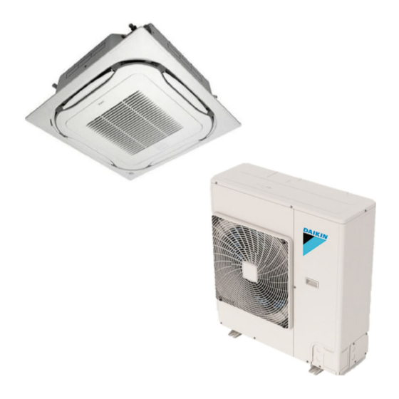
SPLIT SYSTEM
MODEL
Ceiling Mounted Cassette type (Round Flow with Sensing Panel)
FCQ18AAVJU
FCQ24AAVJU
FCQ30AAVJU
FCQ36AAVJU
FCQ42AAVJU
FCQ48AAVJU
Read these instructions carefully before installation.
Keep this manual in a handy place for future reference.
This manual should be left with the equipment owner.
Lire soigneusement ces instructions avant l'installation.
Conserver ce manuel à portée de main pour référence ultérieure.
Ce manuel doit être donné au propriétaire de l'équipement.
Lea cuidadosamente estas instrucciones antes de instalar.
Guarde este manual en un lugar a mano para leer en caso de tener alguna duda.
Este manual debe permanecer con el propietario del equipo.
INSTALLATION MANUAL
Air Conditioners
English
Français
Español
Advertisement
Table of Contents

Related Manuals for Daikin FCQ18AAVJU


Summary of Contents for Daikin FCQ18AAVJU
- Page 1 INSTALLATION MANUAL SPLIT SYSTEM Air Conditioners MODEL Ceiling Mounted Cassette type (Round Flow with Sensing Panel) FCQ18AAVJU FCQ24AAVJU English FCQ30AAVJU FCQ36AAVJU FCQ42AAVJU FCQ48AAVJU Français Read these instructions carefully before installation. Español Keep this manual in a handy place for future reference.
-
Page 2: Table Of Contents
CONTENTS DANGER • Refrigerant gas is heavier than air and replaces oxygen. SAFETY CONSIDERATIONS.........[i] [ii] A massive leak can lead to oxygen depletion, especially 1. BEFORE INSTALLATION ..........1 in basements, and an asphyxiation hazard could occur 2. SELECTION OF INSTALLATION LOCATION ..... 2 leading to serious injury or death. - Page 3 (c) Near machinery emitting electromagnetic waves. Elec- specified by Daikin are used, fire or explosion may occur. tromagnetic waves may disturb the operation of the • Do not install in a wet room such as a bathroom or laundry control system and cause the unit to malfunction.
-
Page 4: Before Installation
1. BEFORE INSTALLATION Name Sealing material When unpacking the indoor unit or moving the unit after Quantity 1 each 1 sheet 1 pc. unpacked, hold the hanger brackets (4 places) and do not (10) Large apply force to other parts (particularly refrigerant piping, drain piping and resin parts). -
Page 5: Selection Of Installation Location
CARRY OUT THE WORK GIVING CAUTION Points of the operation explanation TO THE FOLLOWING ITEMS AND AFTER THE In addition to the general usage, since the items in the WORK IS COMPLETED, CHECK THEM AGAIN. operation manual with the WARNING and CAUTION marks are likely to result in human bodily injuries and property damages, it is neces sary (1) Items to be checked after the installation work is... - Page 6 (3) Direction of the air discharge (NOTE 1) • Select the number of directions of the optimum air Indoor unit Exhaust fan Indoor unit Lighting discharge for the shape or the position of the room. • The number of directions of the air discharge can be *60 (1,500) 60 (1,500) or more...
-
Page 7: Preparation Before Installation
3. PREPARATION BEFORE INSTALLATION [unit: in. (mm)] Frame (1) Check the relation of location between the ceiling opening and the indoor unit suspension bolts. Refrigerant piping Ceiling material ≤1-3/8 (35) ≤1-3/8 (35) ≥13/16 ≥13/16 (20) (20) 33-7/8 to 35-7/8 (860 – 910) Suspension (Ceiling-opening dimension) (Ceiling-panel... - Page 8 (1) Install the indoor unit temporarily. < Installation work after the ceiling work is finished > • Fix the hanger bracket to the suspension bolt. (3) Adjust the indoor unit to be located at the correct posi- Make sure to securely fix the hanger bracket with the tion.
-
Page 9: Refrigerant Piping Work
• For the dimension of flared part and the tightening CAUTION torque, refer to the Table 2. • Install the indoor unit horizontally. • Use the flare nuts attached to the piping of indoor unit. If the indoor unit is inclined and the drain piping side gets •... - Page 10 Table 3 Gas piping insulating method Piping size Tightening Recommended arm length of Joint insulating [in. (mm)] angle tool used [in. (mm)] material (8) f 3/8 (9.5) 60° – 90° Approx. 8 (200) (Accessory) f 5/8 (15.9) 30° – 60° Approx.
-
Page 11: Drain Piping Work
• Before brazing refrigerant piping, have nitrogen flow Drain hose (1) Drain piping through the refrigerant piping and substitute air with (Accessory) (Field supply) nitrogen (NOTE 1) (Refer to Fig. 13). Then, carry out brazing (NOTE 2). Drain socket After all the brazing works are finished, carry out flare (Field supply) connection with the indoor unit. - Page 12 <In case of sticking vinyl tape> CAUTION • Do not apply excessive force to the attached drain hose Tightened part (1) by bending or twisting it. This could cause water leakage. • In case of centralized drain piping, carry out piping work Vinyl tape according to the procedure shown in the fol lowing Fig.
-
Page 13: Electric Wiring Work
• After checking the drainage of water, refer to Fig. 20 4. When the power supply is turned on, the drain pump and attach the sealing material (14) to perform the will operate. Drainage can be checked at the trans- thermal insulation of the drain socket. - Page 14 Hz Volts MCA MOP Terminal for power supply wiring 1.08 ± 0.10 range (1.47 ± 0.14) Ground terminal FCQ18AAVJU 0.07 (53) • Do not carry out soldering finish when stranded wirings FCQ24AAVJU 0.07 (53) are used. FCQ30AAVJU 15 0.14 (106) 0.8 208/ Max.
- Page 15 • Use a 90° elbow type of conduit with dimensions Fig. 23-1 to prevent it from hitting the swing motor hous- ing of decoration panel. • Do not dispose the screw which assembles casing and resin together. The screw will be used to install conduit mounting plate.
- Page 16 < No. 2 system: When using 2 remote controllers > Wiring through hole Power supply Outdoor single phase Remote controller unit 60Hz 208/230V wiring/transmission wiring Control box IN/D OUT/D Sealing material (Small) (13) (Accessory) Putty or insulation (Field supply) Fig. 24 <<Mending method of wiring through hole>>...
-
Page 17: Mounting Decoration Panel
9. FIELD SETTING 7-7 FOR CENTRALIZED CONTROL • When centralized equipment (such as centralized control- <<Refer to also the installation manual attached to the ler) is used for control, it is required to set the group No. on outdoor unit.>> the remote controller. -
Page 18: Test Operation
9-2 SETTING AIR DISCHARGE DIRECTION 9-7 SETTING AIR DISCHARGE DIRECTION • Refer to the installation manual attached to the sealing ma- • When changing air discharge setting (2-way or 3-way air terial of air discharge outlet sold separately and engineer- discharge), set the SECOND CODE NO. - Page 19 NOTE When performing the test operation, always attach the decora- tion panel. Otherwise, this may cause condensation. CAUTION After test operation is completed, check the items men- tioned in Clause 2: (2) Items to be checked at time of delivery on page 2. If the interior finish work is not completed when the test operation is finished, for protection of the air con ditioner, ask the customer not to operate the air conditioner until...
- Page 20 Daikin Texas Technology Park, 19001 Kermier Road, Waller, TX, 77484, U.S.A. 3P693452-2 EM21A045 (2209)
Need help?
Do you have a question about the FCQ18AAVJU and is the answer not in the manual?
Questions and answers