MULTIQUIP Mikasa Series Operation Manual
One-way plate compactor
Hide thumbs
Also See for Mikasa Series:
- Operation and parts manual (116 pages) ,
- Operation manual (90 pages) ,
- Manual (64 pages)
Table of Contents
Advertisement
Quick Links
OPERATION MANUAL
SERIES
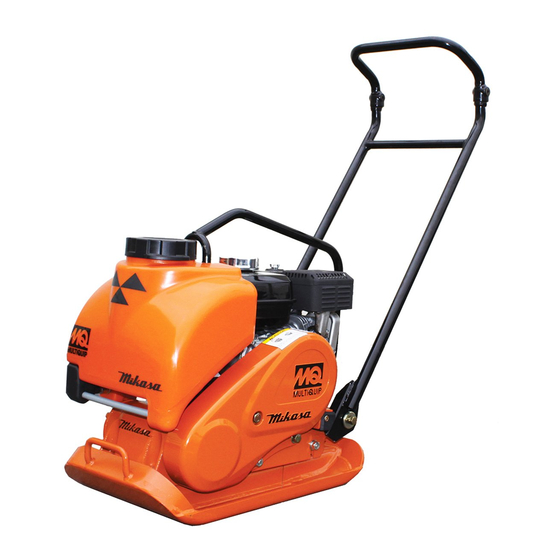
MODEL MVCe64V
ONE-WAY PLATE COMPACTOR
(HONDA GXE2.OH DC POWER UNIT
HONDA DP72104Z BATTERY)
Revision #0 (06/28/21)
To find the latest revision of this publication or
associated parts manual, visit our website at:
www.discount-equipment.com
THIS MANUAL MUST ACCOMPANY THE EQUIPMENT AT ALL TIMES.
Advertisement
Table of Contents


Need help?
Do you have a question about the Mikasa Series and is the answer not in the manual?
Questions and answers