Sign In
Upload
Download
Table of Contents
Contents
Add to my manuals
Delete from my manuals
Share
URL of this page:
HTML Link:
Bookmark this page
Add
Manual will be automatically added to "My Manuals"
Print this page
×
Bookmark added
×
Added to my manuals
Manuals
Brands
Applanix Manuals
Marine Equipment
POS MV V4
User manual
Applanix POS MV V4 User Manual
Hide thumbs
1
2
3
4
5
6
7
8
9
Table Of Contents
10
11
12
13
14
15
16
17
18
19
20
21
22
23
24
25
26
27
28
29
30
31
32
33
34
35
36
37
38
39
40
41
42
43
44
45
46
47
48
49
50
51
52
53
54
55
56
57
58
59
60
61
62
63
64
65
66
67
68
69
70
71
72
73
74
75
76
77
78
79
80
81
82
83
84
85
86
87
88
89
90
91
92
93
94
95
96
97
98
99
100
101
102
103
104
105
106
107
108
109
110
111
112
113
114
115
116
117
118
119
120
121
122
123
124
125
126
127
128
129
130
131
132
133
134
135
136
137
138
139
140
141
142
143
144
145
146
147
148
149
150
151
152
153
154
155
156
157
158
159
160
161
162
163
164
165
166
167
168
169
170
171
172
173
174
175
176
177
178
179
180
181
182
183
184
185
186
187
188
189
190
191
192
193
194
195
196
197
198
199
200
201
202
203
204
205
206
207
208
209
210
211
212
213
214
215
216
217
218
219
220
221
222
223
224
225
226
227
228
229
230
231
232
233
234
235
236
237
238
239
240
241
242
243
244
245
246
247
248
249
250
251
252
253
254
255
256
257
258
259
260
261
262
263
264
265
266
267
268
269
270
271
272
273
274
275
276
277
278
279
280
281
282
283
284
285
286
287
288
289
290
291
292
293
294
295
296
297
298
299
300
301
302
303
304
305
306
307
308
309
310
311
312
313
314
315
316
317
318
319
320
321
322
323
324
325
326
327
328
329
330
331
332
333
334
335
336
337
338
339
340
341
342
343
344
345
346
347
348
349
350
351
352
page
of
352
Go
/
352
Contents
Table of Contents
Troubleshooting
Bookmarks
Table of Contents
Table of Contents
Introduction
System Description and Overview
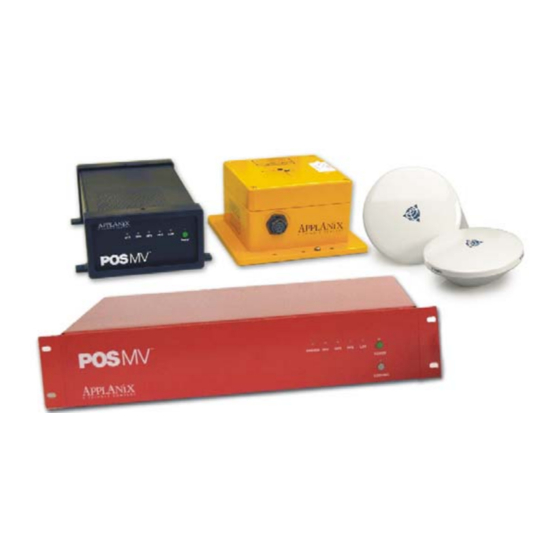
Figure 1: Typical POS MV Components
Operating Modes
Subsystems
GNSS Azimuth Measurement Subsystem
Table 1: System Performance
Figure 2: Heading Measurement Without GAMS
Figure 3: Heading Measurement with GAMS
Functions
Output Summary
Controller Software
Installation
Handling Precautions
Inertial Measurement Unit
POS Computer System
GNSS Antennas
Unpacking and Storage
Storage
Site Preparation
Power Requirements
Environmental Requirements
Installation
GNSS System
Figure 4: GNSS Antenna
Inertial Measurement Unit
Figure 5: Typical IMU Mounting Features
POS Computer System - POS MV V4
Figure 6: PCS Rear Panel - POS MV V4
Table 2: Connector/Cable Summary - POS MV V4
POS Computer System - POS MV V4-1
Figure 7: PCS Rear Panel - POS MV V4-1
Table 3: Connector/Cable Summary - POS MV V4-1
Interfaces
Power Interface
Figure 8: PWR Connector Pin Arrangement
Table 4: PWR Connector Pin Assignment
IMU Interface
I/O Interface Connector - POS MV V4-1
Table 5: I/O Connector Pin Assignment - POS MV V4-1
Figure 9: I/O Connector Pin Arrangement - POS MV V4-1
COM (1) through COM (5) Interface
Table 6: COM Connectors Pin Assignment - POS MV V4
GNSS 1 and GNSS 2 Interface
Table 7: COM Port Configuration
Table 8: GNSS Connectors Pin Assignment - POS MV V4
Events Interface
Table 9: GNSS Port Configuration
Table 10: EVENT Connector Pin Assignment
Figure 10: Type I Event Generator - I/O Configuration
Figure 11: Type II Event Generator - I/O Configuration
Figure 12: Open Collector Transistor Output Event Generator
Figure 13: Mechanical Switch Event Generator - I/O Configuration
Ethernet Interface
Table 11: Ethernet Connector Pin Assignment - POS MV V4
Analog Interface
PPS Interface
Figure 14: PPS Port Signal Sources - Functional Diagram
ANT1 and ANT2 Interfaces
I2C Interface
Ancillary Equipment Interfaces
Installation Parameters
Lever Arm Distances
Antenna Separation
Mounting Angles
Figure 15: Right-Hand Orthogonal System
Installation Checklist
Interfaces and Data Formats
LAN (Ethernet) Data
I2C (Analog) Data
COM Ports
Table 12: Default COM Port Settings
NMEA Data Formats
Table 13: $INGGA Sentence Format
Table 14: $INGGK Sentence Format
Table 15: $INHDT Sentence Format
Table 16: $INVTG Sentence Format
Table 17: $INGST Sentence Format
Figure 16: $INGST Sentence Nomenclature
Table 18: $PASHR Sentence Format
Table 19: $PRDID Sentence Format
Table 20: $INZDA Sentence Format
Table 21: $UTC Sentence Format
Table 22: $INPPS Sentence Format
Binary Data Formats
Table 23: TSS1 Output Format
Table 24: Simrad 1000 Digital Output Format
Table 25: Simrad 3000 Digital Output Format
Table 26: TSM 5265 Digital Output Format
Table 27: Atlas Output Format
Table 28: PPS Digital Output Format
Table 29: Time of PPS Digital Output Format
GNSS Ports
Physical Interface
Table 30: GNSS1 and 2 Port Settings
System Configuration
Power-On
POS MV Power-On
Figure 17: PCS Front and Rear Panels - POS MV V4
Figure 18: PCS Front Panel - POS MV V4-1
Initial Power-On Considerations
MV-Posview Controller Program
MV-Posview Controller - Initial Use
Figure 19: Posview POS Internet Address
POS MV Configuration
Figure 20: Configuration Data Refinement
Configuration Data
Figure 21: Posview Lever Arms & Mounting Angles Tab
Figure 22: Posview Sensor Mounting Tab
Figure 23: Calibration Control Screen
Figure 24: Controller Tags, Multipath & Autostart Tab
Figure 25: User Time Data Screen
Figure 26: Posview Input/Output Port Setup
Figure 27: Posview Analog Port Setup
Table 32: Formula Type Definition
Figure 29: Posview GNSS Receiver Configuration
Initial GNSS Configuration
Figure 31: Posview GAMS Parameters Setup
Figure 32: Posview GAMS Installation Wizard
Figure 33: Posview Settings Menu, Status and Attitude Panes
Power-Off
Save Changes
POS MV Power-Off
Figure 34: PCS Front and Rear Panels - POS MV V4
Figure 35: PCS Front Panel - POS MV V4-1
Save Settings
Making Changes
Manage Multiple Configurations
Password Protection
Figure 36: Posview Controller Password Protection
System Operation
MV-Posview Controller Program
Modes of Operation
PCS Ethernet Connection
Monitoring POS MV
Main Window Regions
POS MV Status Region
Figure 37: Posview Controller Main Window
Figure 38: Posview User Parameter Accuracy
Sensor Navigation Data
Figure 39: Posview Navigation Data at Sensors
Faults and Messages
Figure 40: Posview Fault Detection
Figure 41: Posview Message Log
Data Logging
Ethernet Logging
Ethernet Real-Time Output
Data Logging Control
Figure 42: Posview Data Logging Control
Operation with GAMS
Normal Operation
Figure 43: Posview GAMS Solution and Status Pane
Abnormal Behaviour
Repeatedly Rejected Carrier Phase Ambiguities
Installation Parameters
Figure 44: Posview GAMS Parameters Setup
Stand-Alone Operation
Trueheave Operation
Overview
Figure 45: Trueheave Functional Block Diagram
Configuration Requirements
Initialization Requirements
Data Output
Trueheave Procedure
Figure 46: Posview Heave Data
Figure 47: Posview Status and Accuracy Panes
Specifications
Tools and Diagnostics
GNSS Configuration
GNSS Reset
GNSS Data
Figure 48: Posview GNSS Data
Diagnostics
Control Diagnostics
Figure 49: Posview Binary/Analog Diagnostics
Display Diagnostics
Regular Maintenance
Inertial Measurement Unit
GNSS Antennas
POS Computer System
Technical Support
Fault Identification
Component Description
Inertial Measurement Unit
GNSS Antennas
POS Computer System
Fault Identification
Front Panel Indicators
Figure 50: PCS Front Panels
Fault Detection
Figure 51: Posview Fault Detection
Figure 52: Posview Fault Detection - IMU and GNSS Corr. Tabs
Message Log
Figure 53: Posview Message Log
Table 34: Message Log Entries
Status Warning Messages
Remove and Replace Procedures
Figure 54: PCS Front Panels
Inertial Measurement Unit
Figure 55: PCS Rear Panel - POS MV V4-1
Figure 56: PCS Rear Panel - POS MV V4
GNSS Antenna
IMU Cable
GNSS Antenna Cable
POS Computer System
Troubleshooting
Total System Failure
Initialization Failure
Figure 57: Posview Other Diagnostic
GNSS Not Available
Figure 58: Posview GNSS Data - Receiver Status Pane
Figure 59: Posview Primary GNSS Diagnostics
GAMS Not Ready
Serial Communications Problem
Figure 60: Posview Input/Output Port Setup
Figure 61: Posview NMEA & Binary Output Diagnostic
Ethernet Communications Problem
Figure 62: Posview Base 1 Diagnostic
Figure 63: (1 of 2) Ethernet Communications Failure
Contact Applanix
Figure 64: (2 of 2) Ethernet Communications Failure
How to Reach Customer Support
Returns
Theory of Operation
Inertial Navigation
Figure 65: Example of ins Navigation on a Spherical Earth
Figure 66: Gimballed ins Platform Structure
Figure 67: Strap-Down ins Generic Architecture
Heave Filter
Figure 68: Heave Filter Architecture
Figure 69: Percentage Steady State Error with Heave Bandwidth
Figure 70: Percentage Steady State Error with Damping Ratio
Figure 71: Heave Filter Transient Behaviour with Heave Bandwidth
GNSS Azimuth Measurement Subsystem
Figure 72: Heave Filter Transient Behaviour with Damping Ratio
Heading Measurements
Baselines
Figure 73: Geographic Antenna Baseline Vector
Figure 74: Baseline Comparison
Baseline Measurement
Figure 75: IMU and GNSS Antenna Geometry
Carrier Phase Differential Position
Figure 76: Carrier Phase Cycle Measurement
Figure 77: Feasible Position Solutions from One Satellite
Figure 78: Feasible Position Solutions from Two Satellites
Figure 79: Feasible Position Solutions from Three Satellites
Alignment
Figure 80: Horizontal Acceleration Error in a Tilted Platform
Error Sources
Aided Inertial Navigation
Figure 81: Example of Complementary Navigation Sensor Blending
Training
Software Installation
Supplied Software
Hardware and Software Requirements
MV-Posview Controller Program
Table 37: Controlling PC Requirements
Firmware Upgrade
Drawings
Figure 82: IMU Type 17 Footprint
Figure 83: IMU Type 2 Footprint
Figure 84: IMU Type 2 Base Plate Footprint
Figure 87: PCS Footprint - POS MV V4-1
Figure 88: PCS Footprint - POS MV V4
Figure 89: Power Cord - POS MV V4
Patch Test
Survey Area
Figure 90: Ideal Survey Calibration Area
Figure 91: Correct Roll Calibration
Figure 92: Incorrect Roll Calibration
Survey Procedure
IP68 Connector Handling Instructions
Handling Instructions
POS-GNSS Timing
Background
Advertisement
Quick Links
Download this manual
POS MV V4 User Guide
PUBS-MAN-000513
Revision 3
Copyright © Applanix Corporation, 2009
Table of
Contents
Previous
Page
Next
Page
1
2
3
4
5
Advertisement
Table of Contents
Need help?
Do you have a question about the POS MV V4 and is the answer not in the manual?
Ask a question
Questions and answers
Related Manuals for Applanix POS MV V4
Marine Equipment Applanix POS MV 320 User Manual
(352 pages)
Marine Equipment Applanix POS MV WaveMaster User Manual
(352 pages)
This manual is also suitable for:
Pos mv v4-1
Pos mv 320
Pos mv wavemaster
Pos mv wavemaster rm
Table of Contents
Save PDF
Print
Rename the bookmark
Delete bookmark?
Delete from my manuals?
Login
Sign In
OR
Sign in with Facebook
Sign in with Google
Upload manual
Upload from disk
Upload from URL


Need help?
Do you have a question about the POS MV V4 and is the answer not in the manual?
Questions and answers