Sign In
Upload
Manuals
Brands
Applanix Manuals
Marine Equipment
POS MV WaveMaster RM
Applanix POS MV WaveMaster RM Manuals
Manuals and User Guides for Applanix POS MV WaveMaster RM. We have
1
Applanix POS MV WaveMaster RM manual available for free PDF download: User Manual
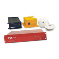
Applanix POS MV WaveMaster RM User Manual (352 pages)
Brand:
Applanix
| Category:
Marine Equipment
| Size: 2 MB
Table of Contents
Table of Contents
10
Introduction
27
System Description and Overview
28
Figure 1: Typical POS MV Components
28
Operating Modes
31
Subsystems
32
GNSS Azimuth Measurement Subsystem
34
Table 1: System Performance
35
Figure 2: Heading Measurement Without GAMS
36
Figure 3: Heading Measurement with GAMS
39
Functions
40
Output Summary
45
Controller Software
46
Installation
47
Handling Precautions
47
Inertial Measurement Unit
47
POS Computer System
48
GNSS Antennas
48
Unpacking and Storage
48
Storage
49
Site Preparation
49
Power Requirements
50
Environmental Requirements
51
Installation
52
GNSS System
52
Figure 4: GNSS Antenna
54
Inertial Measurement Unit
56
Figure 5: Typical IMU Mounting Features
58
POS Computer System - POS MV V4
59
Figure 6: PCS Rear Panel - POS MV V4
61
Table 2: Connector/Cable Summary - POS MV V4
61
POS Computer System - POS MV V4-1
64
Figure 7: PCS Rear Panel - POS MV V4-1
65
Table 3: Connector/Cable Summary - POS MV V4-1
65
Interfaces
66
Power Interface
67
Figure 8: PWR Connector Pin Arrangement
67
Table 4: PWR Connector Pin Assignment
67
IMU Interface
68
I/O Interface Connector - POS MV V4-1
68
Table 5: I/O Connector Pin Assignment - POS MV V4-1
69
Figure 9: I/O Connector Pin Arrangement - POS MV V4-1
71
COM (1) through COM (5) Interface
72
Table 6: COM Connectors Pin Assignment - POS MV V4
72
GNSS 1 and GNSS 2 Interface
73
Table 7: COM Port Configuration
73
Table 8: GNSS Connectors Pin Assignment - POS MV V4
73
Events Interface
74
Table 9: GNSS Port Configuration
74
Table 10: EVENT Connector Pin Assignment
75
Figure 10: Type I Event Generator - I/O Configuration
76
Figure 11: Type II Event Generator - I/O Configuration
77
Figure 12: Open Collector Transistor Output Event Generator
77
Figure 13: Mechanical Switch Event Generator - I/O Configuration
78
Ethernet Interface
79
Table 11: Ethernet Connector Pin Assignment - POS MV V4
80
Analog Interface
81
PPS Interface
81
Figure 14: PPS Port Signal Sources - Functional Diagram
82
ANT1 and ANT2 Interfaces
83
I2C Interface
83
Ancillary Equipment Interfaces
83
Installation Parameters
84
Lever Arm Distances
87
Antenna Separation
93
Mounting Angles
93
Figure 15: Right-Hand Orthogonal System
95
Installation Checklist
97
Interfaces and Data Formats
101
LAN (Ethernet) Data
101
I2C (Analog) Data
102
COM Ports
103
Table 12: Default COM Port Settings
103
NMEA Data Formats
104
Table 13: $INGGA Sentence Format
105
Table 14: $INGGK Sentence Format
108
Table 15: $INHDT Sentence Format
110
Table 16: $INVTG Sentence Format
110
Table 17: $INGST Sentence Format
112
Figure 16: $INGST Sentence Nomenclature
113
Table 18: $PASHR Sentence Format
114
Table 19: $PRDID Sentence Format
115
Table 20: $INZDA Sentence Format
116
Table 21: $UTC Sentence Format
117
Table 22: $INPPS Sentence Format
118
Binary Data Formats
119
Table 23: TSS1 Output Format
120
Table 24: Simrad 1000 Digital Output Format
122
Table 25: Simrad 3000 Digital Output Format
124
Table 26: TSM 5265 Digital Output Format
126
Table 27: Atlas Output Format
127
Table 28: PPS Digital Output Format
128
Table 29: Time of PPS Digital Output Format
128
GNSS Ports
129
Physical Interface
129
Table 30: GNSS1 and 2 Port Settings
130
System Configuration
131
Power-On
131
POS MV Power-On
132
Figure 17: PCS Front and Rear Panels - POS MV V4
133
Figure 18: PCS Front Panel - POS MV V4-1
133
Initial Power-On Considerations
135
MV-Posview Controller Program
136
MV-Posview Controller - Initial Use
137
Figure 19: Posview POS Internet Address
140
POS MV Configuration
141
Figure 20: Configuration Data Refinement
141
Configuration Data
142
Figure 21: Posview Lever Arms & Mounting Angles Tab
143
Figure 22: Posview Sensor Mounting Tab
144
Figure 23: Calibration Control Screen
145
Figure 24: Controller Tags, Multipath & Autostart Tab
148
Figure 25: User Time Data Screen
149
Figure 26: Posview Input/Output Port Setup
150
Figure 27: Posview Analog Port Setup
152
Table 32: Formula Type Definition
152
Figure 29: Posview GNSS Receiver Configuration
156
Initial GNSS Configuration
157
Figure 31: Posview GAMS Parameters Setup
159
Figure 32: Posview GAMS Installation Wizard
160
Figure 33: Posview Settings Menu, Status and Attitude Panes
163
Power-Off
166
Save Changes
167
POS MV Power-Off
168
Figure 34: PCS Front and Rear Panels - POS MV V4
168
Figure 35: PCS Front Panel - POS MV V4-1
169
Save Settings
170
Making Changes
170
Manage Multiple Configurations
170
Password Protection
171
Figure 36: Posview Controller Password Protection
173
System Operation
174
MV-Posview Controller Program
175
Modes of Operation
175
PCS Ethernet Connection
175
Monitoring POS MV
176
Main Window Regions
176
POS MV Status Region
177
Figure 37: Posview Controller Main Window
177
Figure 38: Posview User Parameter Accuracy
181
Sensor Navigation Data
182
Figure 39: Posview Navigation Data at Sensors
183
Faults and Messages
184
Figure 40: Posview Fault Detection
185
Figure 41: Posview Message Log
186
Data Logging
187
Ethernet Logging
187
Ethernet Real-Time Output
188
Data Logging Control
188
Figure 42: Posview Data Logging Control
189
Operation with GAMS
191
Normal Operation
191
Figure 43: Posview GAMS Solution and Status Pane
192
Abnormal Behaviour
195
Repeatedly Rejected Carrier Phase Ambiguities
198
Installation Parameters
199
Figure 44: Posview GAMS Parameters Setup
200
Stand-Alone Operation
201
Trueheave Operation
203
Overview
203
Figure 45: Trueheave Functional Block Diagram
203
Configuration Requirements
204
Initialization Requirements
204
Data Output
204
Trueheave Procedure
205
Figure 46: Posview Heave Data
205
Figure 47: Posview Status and Accuracy Panes
206
Specifications
207
Tools and Diagnostics
211
GNSS Configuration
211
GNSS Reset
211
GNSS Data
212
Figure 48: Posview GNSS Data
212
Diagnostics
213
Control Diagnostics
213
Figure 49: Posview Binary/Analog Diagnostics
214
Display Diagnostics
215
Regular Maintenance
215
Inertial Measurement Unit
216
GNSS Antennas
216
POS Computer System
217
Technical Support
217
Fault Identification
218
Component Description
219
Inertial Measurement Unit
220
GNSS Antennas
220
POS Computer System
220
Fault Identification
221
Front Panel Indicators
222
Figure 50: PCS Front Panels
222
Fault Detection
224
Figure 51: Posview Fault Detection
226
Figure 52: Posview Fault Detection - IMU and GNSS Corr. Tabs
227
Message Log
228
Figure 53: Posview Message Log
228
Table 34: Message Log Entries
229
Status Warning Messages
235
Remove and Replace Procedures
242
Figure 54: PCS Front Panels
242
Inertial Measurement Unit
243
Figure 55: PCS Rear Panel - POS MV V4-1
243
Figure 56: PCS Rear Panel - POS MV V4
243
GNSS Antenna
245
IMU Cable
247
GNSS Antenna Cable
248
POS Computer System
249
Troubleshooting
250
Total System Failure
251
Initialization Failure
252
Figure 57: Posview Other Diagnostic
252
GNSS Not Available
253
Figure 58: Posview GNSS Data - Receiver Status Pane
253
Figure 59: Posview Primary GNSS Diagnostics
255
GAMS Not Ready
256
Serial Communications Problem
257
Figure 60: Posview Input/Output Port Setup
258
Figure 61: Posview NMEA & Binary Output Diagnostic
259
Ethernet Communications Problem
260
Figure 62: Posview Base 1 Diagnostic
260
Figure 63: (1 of 2) Ethernet Communications Failure
261
Contact Applanix
262
Figure 64: (2 of 2) Ethernet Communications Failure
262
How to Reach Customer Support
264
Returns
265
Theory of Operation
266
Inertial Navigation
267
Figure 65: Example of ins Navigation on a Spherical Earth
272
Figure 66: Gimballed ins Platform Structure
276
Figure 67: Strap-Down ins Generic Architecture
279
Heave Filter
280
Figure 68: Heave Filter Architecture
281
Figure 69: Percentage Steady State Error with Heave Bandwidth
286
Figure 70: Percentage Steady State Error with Damping Ratio
287
Figure 71: Heave Filter Transient Behaviour with Heave Bandwidth
288
GNSS Azimuth Measurement Subsystem
289
Figure 72: Heave Filter Transient Behaviour with Damping Ratio
289
Heading Measurements
291
Baselines
291
Figure 73: Geographic Antenna Baseline Vector
292
Figure 74: Baseline Comparison
293
Baseline Measurement
294
Figure 75: IMU and GNSS Antenna Geometry
296
Carrier Phase Differential Position
297
Figure 76: Carrier Phase Cycle Measurement
299
Figure 77: Feasible Position Solutions from One Satellite
300
Figure 78: Feasible Position Solutions from Two Satellites
300
Figure 79: Feasible Position Solutions from Three Satellites
301
Alignment
303
Figure 80: Horizontal Acceleration Error in a Tilted Platform
304
Error Sources
306
Aided Inertial Navigation
307
Figure 81: Example of Complementary Navigation Sensor Blending
311
Training
313
Software Installation
314
Supplied Software
315
Hardware and Software Requirements
315
MV-Posview Controller Program
316
Table 37: Controlling PC Requirements
316
Firmware Upgrade
317
Drawings
319
Figure 82: IMU Type 17 Footprint
319
Figure 83: IMU Type 2 Footprint
319
Figure 84: IMU Type 2 Base Plate Footprint
320
Figure 87: PCS Footprint - POS MV V4-1
322
Figure 88: PCS Footprint - POS MV V4
323
Figure 89: Power Cord - POS MV V4
324
Patch Test
325
Survey Area
325
Figure 90: Ideal Survey Calibration Area
326
Figure 91: Correct Roll Calibration
328
Figure 92: Incorrect Roll Calibration
328
Survey Procedure
330
IP68 Connector Handling Instructions
331
Handling Instructions
331
POS-GNSS Timing
332
Background
332
Advertisement
Advertisement
Related Products
Applanix POS MV WaveMaster
Applanix POS MV 320
Applanix POS MV V4
Applanix POS MV V4-1
Applanix Categories
Marine Equipment
Control Unit
Car Navigation system
Receiver
Antenna
More Applanix Manuals
Login
Sign In
OR
Sign in with Facebook
Sign in with Google
Upload manual
Upload from disk
Upload from URL