
Related Manuals for Applanix POS MV 320


Summary of Contents for Applanix POS MV 320
- Page 1 POS MV V4 User Guide PUBS-MAN-000513 Revision 3 Copyright © Applanix Corporation, 2009...
- Page 2 Applanix Corporation (here after referred to as Applanix) provides it “as is” and without express, implied, or limited warranty of any kind. In no event shall Applanix be liable for any loss or damage caused by the use of this manual.
- Page 3 360 degree termination at the backshells of both connectors. Power Cord - Applanix ships a specially constructed power cord with its POS MV V4 ac products and is detailed in Appendix E. Otherwise, the customer is responsible for supplying and using a compliant power cord.
- Page 4 Ottawa, Ontario, Canada K1V 1H2 Equipment Model Designation: POS MV V4 Equipment Description: POS MV V4 is a fully integrated, turnkey position and orientation system for marine vehicles. Application of Council Directive: 73/23/EEC on the harmonization of the laws related to Member States relating to electrical equipment designed...
- Page 5 Ottawa, Ontario, Canada K1V 1H2 Equipment Model Designation: POS MV V4-1 Equipment Description: POS MV V4-1 is a fully integrated, turnkey position and orientation system for marine vehicles. Application of Council Directive: 73/23/EEC on the harmonization of the laws related to Member States relating to electrical equipment designed...
- Page 6 Section 15.21 Information to the user. Changes or modifications not expressly approved by Applanix could void the user's authority to operate the equipment. Section 15.105 Information to the user. NOTE: This equipment has been tested and found to comply with the limits for a Class A digital device, pursuant to Part 15 of the FCC Rules.
- Page 7 We endeavour to meet your needs, not only when you purchase and use our products, but also when you are ready to dispose of them. Applanix is actively pursuing, and will continue to pursue, the expanded use of environmentally friendly materials in all its products. In addition, we have established a convenient and environmentally friendly recycling program.
- Page 8 Menu statement - bold font (e.g. ‘select Insert, AutoText, Closing window menu’ or ‘select Insert | AutoText | Closing window menu’); a mixture is acceptable but, consistency is preferable • Web address statement - bold font (e.g. ‘select http://www.applanix.com from’) Copyright © Applanix Corporation, 2009...
- Page 9 Electrostatic Discharge Fragile/Breakable (ESD) sensitive material Hint - provides a suggested Electrocution Hazard method or approach Document Number PUBS-MAN-000513, Revision 3, dated 20 January 2009 Copyright © Applanix Corporation, 2009...
-
Page 10: Table Of Contents
Power Requirements .................2-4 Environmental Requirements ............2-5 Installation ....................2-6 GNSS System..................2-6 Inertial Measurement Unit............... 2-10 POS Computer System - POS MV V4..........2-13 POS Computer System - POS MV V4-1......... 2-18 Interfaces....................2-20 Power Interface................2-21 IMU Interface .................. 2-22 I/O Interface Connector - POS MV V4-1......... 2-22 COM (1) through COM (5) Interface .......... - Page 11 POS MV Configuration ................. 4-11 Configuration Data ................4-12 Initial GNSS Configuration .............. 4-27 Power-Off....................4-36 Save Changes................. 4-37 POS MV Power-Off ................. 4-38 Save Settings..................4-40 Making Changes................... 4-40 Manage Multiple Configurations ............4-40 Copyright © Applanix Corporation, 2009...
- Page 12 Installation Parameters ..............5-26 Stand-Alone Operation................5-28 6.0 TrueHeave Operation ....6-1 Overview....................6-1 Configuration Requirements..............6-2 Initialization Requirements ..............6-2 Data Output .....................6-2 TrueHeave Procedure ................6-3 7.0 Specifications ....... 7-1 8.0 Tools and Diagnostics ....8-1 GNSS Configuration................8-1 Copyright © Applanix Corporation, 2009...
- Page 13 GNSS Antenna Cable ..............9-31 POS Computer System..............9-32 Troubleshooting ..................9-33 Total System Failure ............... 9-34 Initialization Failure ................. 9-35 GNSS Not Available................ 9-36 GAMS Not Ready................9-39 Serial Communications Problem............. 9-40 Ethernet Communications Problem ..........9-43 Copyright © Applanix Corporation, 2009...
- Page 14 Hardware and Software Requirements..........D-2 MV-POSView Controller Program ............D-3 Firmware Upgrade ................D-4 Drawings....................E-1 Patch Test ....................F-1 Survey Area ..................F-1 Survey Procedure ................F-6 IP68 Connector Handling Instructions............G-1 Handling Instructions ................G-1 POS-GNSS Timing................. H-1 Background..................H-1 Copyright © Applanix Corporation, 2009...
- Page 15 GNSS Timing Basics.................H-3 POS System Timing................H-5 Glossary Index Copyright © Applanix Corporation, 2009...
- Page 16 Figure 14: PPS Port Signal Sources - Functional Diagram ......2-36 Figure 15: Right-Hand Orthogonal System..........2-49 Figure 16: $INGST Sentence Nomenclature ..........3-13 Figure 17: PCS Front and Rear Panels - POS MV V4 .........4-3 Figure 18: PCS Front Panel - POS MV V4-1..........4-3 Figure 19: POSView POS Internet Address ..........4-10 Figure 20: Configuration Data Refinement ..........4-11...
- Page 17 Figure 32: POSView GAMS Installation Wizard .........4-30 Figure 33: POSView Settings Menu, Status and Attitude Panes....4-33 Figure 34: PCS Front and Rear Panels - POS MV V4 .......4-38 Figure 35: PCS Front Panel - POS MV V4-1 ..........4-39 Figure 36: POSView Controller Password Protection.........4-43 Figure 37: POSView Controller Main Window ..........5-4...
- Page 18 Figure 52: POSView Fault Detection - IMU and GNSS Corr. Tabs....9-10 Figure 53: POSView Message Log.............9-11 Figure 54: PCS Front Panels..............9-25 Figure 55: PCS Rear Panel - POS MV V4-1 ..........9-26 Figure 56: PCS Rear Panel - POS MV V4..........9-26 Figure 57: POSView Other Diagnostic ............9-35 Figure 58: POSView GNSS Data - Receiver Status Pane ......9-36...
- Page 19 Figure 87: PCS Footprint – POS MV V4-1........... E-4 Figure 88: PCS Footprint - POS MV V4............E-5 Figure 89: Power Cord - POS MV V4 ............E-6 Figure 90: Ideal Survey Calibration Area ............. F-2 Figure 91: Correct Roll Calibration............... F-4 Figure 92: Incorrect Roll Calibration ............
- Page 20 Table 3: Connector/Cable Summary - POS MV V4-1 ........2-19 Table 4: PWR Connector Pin Assignment..........2-21 Table 5: I/O Connector Pin Assignment - POS MV V4-1 ......2-23 Table 6: COM Connectors Pin Assignment - POS MV V4 ......2-26 Table 7: COM Port Configuration ...............2-27 Table 8: GNSS Connectors Pin Assignment - POS MV V4 .......2-27...
- Page 21 Table 33: PCS Front Panel Indicators - Fault Identification......9-5 Table 34: Message Log Entries ..............9-12 Table 35: Status Warning Messages ............9-18 Table 36: Effects of Modifying Heave Filter Parameters ......B-20 Table 37: Controlling PC Requirements ............D-3 Copyright © Applanix Corporation, 2009...
- Page 22 Bits Per Second Coarse Acquisition Compact Disk Centimetre Clear to Send Digital to Analog Converter Decibel Direct Current Direction Cosine Matrix Degree (plane angle) DGNSS Differential Global Navigation Satellite System Diameter Dilution of Position Electromagnetic Interference Copyright © Applanix Corporation, 2009...
- Page 23 Global Navigation Satellite System Graphical User Interface HDOP Horizontal Dilution Of Precision Hexadecimal Hour Hertz Input/Output International Electrotechnical Commission IEEE Institute of Electrical and Electronics Engineers Inertial Measurement Unit Inch Inertial Navigation System Input Ingress Protection Internet Protocol Copyright © Applanix Corporation, 2009...
- Page 24 Milliampere Megabit Megabyte Megahertz Millimetre mPOS Mini-Position and Orientation System Not Applicable No Connection North, East and Down NMEA National Marine Electronics Association No Range Given Non-Volatile Memory Output On-the-Fly Personal Computer POS Computer system Copyright © Applanix Corporation, 2009...
- Page 25 Radio Technical Commission for Maritime Services Real-Time Kinematic Ready to Sent Receive Data Second (time interval) Society of Automotive Engineers SCSI Small Computer System Interface System of Units Signal-To-Noise Ratio Space Vehicle sync Synchronous Transmission Control Protocol Copyright © Applanix Corporation, 2009...
- Page 26 Terminal Ready Transistor-Transistor Logic Universal Datagram Protocol Unified National Coarse (Screw Thread) Uninterrupted Power Supply Universal Time Coordinated (or Coordinated Universal Time) Transmit Data Volt Alternating Current Volt Direct Current VDOP Vertical Dilution of Precision Watt Copyright © Applanix Corporation, 2009...
-
Page 27: Introduction
POS MV V4 User Guide Introduction Introduction The Applanix POS MV is a Position and Orientation System for Marine Vessels using a system that provides accurate navigation and attitude data for use by equipment on board the vessel, such as multi-beam sonar, to correct for the effects of vessel motion during survey operations. -
Page 28: System Description And Overview
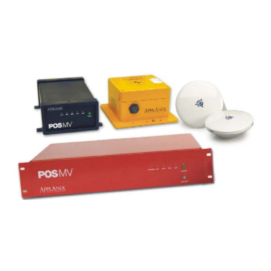
The POS MV product family consists of three models: POS MV 320 - consists of a POS MV V4 PCS and a type 2 IMU. POS MV WaveMaster - consists of a POS MV V4-1 PCS and a type 17 IMU. - Page 29 POS MV V4 User Guide Introduction The POS MV delivers an accurate and comprehensive data set, including: • Geographic position (latitude, longitude and altitude) • Heading • Attitude (roll and pitch) • Vertical displacement (heave) • Velocity • Acceleration •...
- Page 30 POS MV V4 User Guide Introduction With its use of leading-edge technology, POS MV marks a significant breakthrough in the field of aided inertial navigation and precision motion measurement for use in marine applications. The accuracy and stability of measurements delivered by the system remain unaffected by vessel turns, changes of speed, wave-induced motion, or other dynamic manoeuvres.
-
Page 31: Operating Modes
POS MV V4 User Guide Introduction measurements automatically through whichever ports you have selected. Communication between POS MV and the controller program is through a 10/100BaseT Ethernet link: • Data output by POS MV may use the Universal Datagram Protocol... -
Page 32: Subsystems
‘AutoStart’. With AutoStart enabled, the system will transition automatically into navigate mode. Applanix ships the POS MV with AutoStart enabled. Navigate Mode: Navigate Mode is the normal operating mode of POS MV. - Page 33 GNSS signals from the orbiting constellation of satellites. The antennas supplied with the system have excellent phase centre stability. If you use alternative antennas with the POS MV, Applanix cannot guarantee the heading or position performance of the system.
-
Page 34: Gnss Azimuth Measurement Subsystem
POS MV V4 User Guide Introduction GNSS Azimuth Measurement Subsystem GNSS Azimuth Measurement Subsystem (GAMS) is a unique feature of POS MV that allows the system to achieve exceptional accuracy in the measurement of heading. The GAMS subsystem uses two GNSS receivers and antennas to determine a GNSS-based heading that is accurate to ±0.02°... -
Page 35: Table 1: System Performance
POS MV V4 User Guide Introduction Table 1: System Performance Parameter Without GAMS With GAMS Heading 0.2° to 2.0° RMS after POS 0.02° (0.03° for the accuracy: MV achieves full alignment WaveMaster), or better, (depending on the nature of independent of vessel vessel manoeuvres). -
Page 36: Figure 2: Heading Measurement Without Gams
POS MV V4 User Guide Introduction difference in mounting angles between the transducer, the IMU, the vessel and your chosen reference frame. Operation without GAMS Figure 2 and the following paragraphs describe how POS MV computes heading without GAMS. After power-on, and the initialization and self-test routines have finished, the IMU performs a levelling routine to establish a locally level reference frame. - Page 37 POS MV V4 User Guide Introduction 5 to 30 minutes to complete. The time taken to complete this process will depend on the latitude and on the manoeuvres that the vessel performs during the operation. A more accurate and rapid alignment will occur if the vessel performs a number of calibration manoeuvres during the alignment process.
- Page 38 POS MV V4 User Guide Introduction GAMS heading error is largely due to GNSS receiver noise and multipath errors. By blending this information with the IMU data in the Kalman Filter, POS MV can average the GAMS heading error down to a blended heading accuracy of typically 0.02°...
-
Page 39: Figure 3: Heading Measurement With Gams
POS MV V4 User Guide Introduction Figure 3: Heading Measurement with GAMS After alignment, the IMU delivers measurements of multi-beam transducer heading relative to true north. These measurements possess the same accuracy as those of vessel heading defined in the paragraph above. -
Page 40: Functions
2-47, descriptions for instructions to measure the mounting angles of the IMU, multi-beam transducer and ship frames with respect to your chosen reference frame. Functions The Applanix POS MV offers many advanced functions including: • Motion measurement • TrueHeave (software option) •... - Page 41 Analog Interface The analog interface hardware option delivers motion measurements (roll, pitch and heave) for use by external equipment such as an echo-sonar. Contact your Applanix Customer Support representative for the details; refer to page A-1). 1-15 Copyright © Applanix Corporation, 2009...
- Page 42 POS MV V4 User Guide Introduction Position and Velocity Measurement POS MV supplies parameters such as the position, velocity, speed, acceleration and angular rate of the vessel. The system also estimates and displays the accuracy of some of these output parameters.
- Page 43 POS MV V4 User Guide Introduction AutoStart You must first configure the system with the following parameters before it can operate properly when you transition POS MV to its navigate mode: • The lever arm distances including those from the IMU, multi-beam...
- Page 44 POS MV V4 User Guide Introduction post-processed using POSPac to further enhance the quality of seafloor maps generated by multi-beam sonar systems. Contact Applanix for more information on POSPac. Ethernet Real-Time Output High rate data are available from the PCS data port using Universal Datagram Protocol (UDP) broadcasts.
-
Page 45: Output Summary
Event 2 line, it captures the exact time that corresponds to the trigger edge (within a window 1 μs wide). Event records are available for output on the Ethernet data ports. Contact Applanix for advice if you need additional information about the Ethernet group structure. -
Page 46: Controller Software
POS MV V4 User Guide Introduction Controller Software You can use the MV-POSView Controller program to configure POS MV; the controller ships with the POS MV system. For subsequent operation of the POS MV you can use the controller program or you can configure the system to start operating automatically with no further need for operator control. -
Page 47: Installation
Computer System (PCS), the Inertial Measurement Unit (IMU) and the Global Navigation Satellite System (GNSS) antennas should only take a few hours. This section of the POS MV V4 manual explains each stage of the installation. By following these instructions, you can unpack, install and configure the system so that it is ready to operate with minimal delay. -
Page 48: Pos Computer System
POS Computer System Field repair of the PCS is not recommended. If this unit develops a fault or becomes damaged it must be returned to Applanix for repair. Refer to Technical Support and Service on page A-1 for procedures. Consider the following when handling the PCS: •... -
Page 49: Storage
If any damage has occurred, file a claim with the carrier and notify Applanix immediately. Refer to Technical Support and Service on page A-1 for postal address, contact telephone and fax numbers, and e-mail and Web address for Applanix. -
Page 50: Power Requirements
Note: Before installing the POS MV, make certain that adequate mounting provisions exist for all components of the system. Power Requirements Applanix strongly recommends that you arrange to supply electrical power to the POS MV from an Uninterrupted Power Supply (UPS). This is for two reasons: •... -
Page 51: Environmental Requirements
POS MV V4 User Guide Installation GNSS Antennas Both Models Voltage: Supplied by the GNSS receiver via the antenna coaxial cable Both Models Voltage: Supplied by the PCS via the IMU cable Environmental Requirements GNSS Antennas To receive GNSS satellite signals without interruption, the GNSS antennas require a clear view of the sky from horizon to horizon in all directions. -
Page 52: Installation
Important: 1. Equipment shall be installed by qualified personnel. 2. The PCS (POS MV V4) shall be grounded through the ground prong of the power plug; if not, then the safety ground screw shall be used. 3. The PCS (POS MV V4-1) shall be grounded via the safety ground screw. - Page 53 POS MV V4 User Guide Installation The POS MV GNSS antennas may be installed anywhere on the vessel, provided their locations meet the following criteria: • Observe the environmental limitations specified on page 2-5, GNSS Antennas. • Avoid GNSS antenna locations that may experience multipath satellite signals caused by reflections off nearby structures.
-
Page 54: Figure 4: Gnss Antenna
• Secondary antenna to ANT2 port on the PCS Note: POS MV includes two low-loss antenna cables with connectors at each end. These cables are standard length of 15 m (~49 ¼ ft). Applanix can Copyright © Applanix Corporation, 2009... - Page 55 POS MV V4 User Guide Installation supply longer GNSS antenna cables on request, up to a maximum allowable length of 50 m (~164 ft) with a maximum signal loss of eight Decibels (dB). It is not necessary for both cables to be the same length.
-
Page 56: Inertial Measurement Unit
POS MV V4 User Guide Installation 6. Connect the secondary antenna cable to the ANT2 port on the PCS rear panel. Note: You must identify the primary and the secondary antennas clearly. POS MV uses the lever arms distances between your chosen reference point and the primary GNSS antenna to generate a navigation solution. - Page 57 IMU and the PCS. Do not subject the cable to sharp bends or other mechanical stresses. Applanix can supply a longer cable of up to 50 m (~164 ft) in length if necessary. Use suitable clips to support the cable at intervals along its length.
-
Page 58: Figure 5: Typical Imu Mounting Features
POS MV V4 User Guide Installation • Two holes are predrilled in the base to accept 0.25 in (6.35 mm) diameter alignment pins. These holes maintain IMU alignment when the unit is replaced, see Figure 5. Mounting holes accept 0.25 inch diameter bolt... -
Page 59: Pos Computer System - Pos Mv V4
Refer to page 2-38, Installation Parameters for details of these parameters. POS Computer System - POS MV V4 The PCS is the heart of the POS MV V4 systems and is based on an Intel Pentium processor. The PCS footprint is shown in Appendix E. Install the PCS Remove the PCS from its transit case to allow connection and operation. - Page 60 POS MV V4 User Guide Installation Observe the following installation constraints: Do not hang the PCS from the loose panel mounting hardware. Support the PCS weight from underneath while tightening the panel mounting hardware. • Observe the environmental limitations starting on page 7-3.
-
Page 61: Figure 6: Pcs Rear Panel - Pos Mv V4
Type = slow blow, long time lag • Case = 5 mm x 20 mm Figure 6: PCS Rear Panel - POS MV V4 Use Table 2 as a guide when making cable connections to the PCS rear panel. Table 2: Connector/Cable Summary - POS MV V4... - Page 62 POS MV V4 User Guide Installation Table 2: Connector/Cable Summary - POS MV V4 Connector Cable Description • Ethernet interface communicates with a LAN, Straight RJ-45 controlling PC through this 10/100 Base-T through or female port Cross over • Port used to complete initial POS MV...
- Page 63 GNSS antenna female (RG303/U) If the POS MV V4 receives power from an Uninterruptible Power Supply (UPS), make certain that it is operating at the correct voltage; refer to the Power Requirements description on page 2-4 for details. Good grounding practices are essential for proper operation of the POS MV V4 systems.
-
Page 64: Pos Computer System - Pos Mv V4-1
POS Computer System - POS MV V4-1 The PCS is the heart of POS MV V4-1 system and is based on an Intel Pentium processor. The PCS footprint is shown in Appendix E. -
Page 65: Figure 7: Pcs Rear Panel - Pos Mv V4-1
POS MV V4 User Guide Installation Figure 7: PCS Rear Panel - POS MV V4-1 Use Table 3 as a guide when making cable connections to the PCS rear panel. Table 3: Connector/Cable Summary - POS MV V4-1 Connector Port Description Connects to a power converter;... -
Page 66: Interfaces
Interfaces Applanix supplies the necessary cables and adapters for POS MV operation. Customized and additional cables are available and may be procured by contacting Applanix Customer Support; refer to Technical Support and Service on page A-1. -
Page 67: Power Interface
The following paragraphs provide cable and interface details for the active ports on the PCS rear panel, refer to Table 3 on page 2-19 for the POS MV V4-1 and Table 2 on page 2-15 for POS MV V4. Power Interface Power configuration is performed at Applanix prior to delivery. -
Page 68: Imu Interface
Damage to the IMU or the PCS hardware may result. The IMU data/power interface is a multi-pin female circular connector. Contact Applanix for connection details or longer cables; refer to Technical Support and Service on page A-1 for procedures. HYSICAL NTERFACE A double-shielded cable connects the IMU to the PCS. -
Page 69: Table 5: I/O Connector Pin Assignment - Pos Mv V4-1
POS MV V4 User Guide Installation Table 5: I/O Connector Pin Assignment - POS MV V4-1 I/O Cable Signal Signal Mapping I/O Pin Pin Description Type Direction Connector PPS Out 5 V TTL Output (female) Shell PPS Out External PPS In... - Page 70 POS MV V4 User Guide Installation Table 5: I/O Connector Pin Assignment - POS MV V4-1 I/O Cable Signal Signal Mapping I/O Pin Pin Description Type Direction Connector COM 3 TX RS-232 Output DB-9P COM 3 RX RS-232 Input (male)
-
Page 71: Figure 9: I/O Connector Pin Arrangement - Pos Mv V4-1
POS MV V4 User Guide Installation Table 5: I/O Connector Pin Assignment - POS MV V4-1 I/O Cable Signal Signal Mapping I/O Pin Pin Description Type Direction Connector I2C Return I2C +VIN 2 to 4; 12 to17; Reserved 50 to 55 May be used for the TOV pulse output depending on the function assigned to the port. -
Page 72: Com (1) Through Com (5) Interface
Serial cables should not exceed 15 m [~49 ft] in length. To ensure data integrity, use high quality RS-232 cable with its shielding connected through the back shell to ground at both cable ends. Table 5, page 2-23 (POS MV V4- 1) or Table 6 (POS MV V4) provides connector pin assignments and mapping. -
Page 73: Gnss 1 And Gnss 2 Interface
The serial digital port for each GNSS receiver provides access for receiver upgrading of its software. HYSICAL NTERFACE Table 5, page 2-23 (POS MV V4-1) or Table 8 (POS MV V4) provides connector pin assignments and mapping. Table 8: GNSS Connectors Pin Assignment - POS MV V4 Pin Description... -
Page 74: Events Interface
NTERFACE A cable that supports the two events is supplied with the system. Table 5, page 2-23 (POS MV V4-1) or Table 10 (POS MV V4) provides connector pin assignments and mapping. To time tag an event with Universal Time Coordinated (UTC) or GPS Time,... -
Page 75: Table 10: Event Connector Pin Assignment
Event 1 In and Event 2 In are optically isolated digital inputs. Inputs (and their return lines) are un-referenced and are independent of internal POS MV V4 and POS MV V4-1 power supplies and GND. Inputs can be controlled from an external 5V TTL-level source capable of supplying a minimum of 5 - 10 mA of sourcing or sinking current. -
Page 76: Figure 10: Type I Event Generator - I/O Configuration
POS MV V4 User Guide Installation GND reference connected to Isolated Event 1 Signal Return (pin 7). For Event 2, the output must be connected to the Isolated Event 2 (pin 3) with the GND reference connected to Isolated Event 2 Signal Return (pin 8). Outputs from most of the 5 V TTL Logic CMOS devices belong to this group and can directly drive the isolated event inputs. -
Page 77: Figure 11: Type Ii Event Generator - I/O Configuration
POS MV V4 User Guide Installation +5VDC EVENT 1 IN min. 5 mA EVENT 1 IN RETURN 74LS07 EVENT PULSE Figure 11: Type II Event Generator - I/O Configuration +5VDC EVENT 1 IN EVENT 1 IN RETURN 2N2222 EVENT PULSE... -
Page 78: Figure 13: Mechanical Switch Event Generator - I/O Configuration
PCS power supplies or GND. 5. Each isolated Event input must be driven from a separate source. 6. Applanix can provide an events interface box for the event generators (except for Type I and Type II described above). This events interface box produces the proper PCS event input signals from devices that output pulses ranging from 3.3 V to 12 V TTL. -
Page 79: Ethernet Interface
Ensure that Ethernet cables meet the RJ-45 foil shielded Cat5 standard to avoid an impedance mismatch inside the PCS. In addition, the maximum cable length is determined by the Ethernet specification. Table 5, page 2-23 (POS MV V4-1) or Table 11 (POS MV V4) provides connector pin assignments and mapping. 2-33... -
Page 80: Table 11: Ethernet Connector Pin Assignment - Pos Mv V4
POS MV V4 User Guide Installation Table 11: Ethernet Connector Pin Assignment - POS MV V4 Signal Signal Pin Description Type Direction TX + Analog Bidirectional TX - Analog Bidirectional RX + Analog Bidirectional RX - Analog Bidirectional 4, 5, 7, 8... -
Page 81: Analog Interface
NPUT ORMAT The data input to POS MV on the control port is organized into a message structure. Contact Applanix Customer Support, see page A-1, if control commands are generated by software other than MV-POSView. Analog Interface The optional analog interface provides analog outputs of roll, pitch and heading data. -
Page 82: Figure 14: Pps Port Signal Sources - Functional Diagram
NTERFACE A cable must be constructed and installed to couple the 1PPS signals; Table 5, page 2-23 (POS MV V4-1) or Table 2, page 2-15 (POS MV V4) provides connector pin assignments and mapping. The PPS output port is an active circuit. Ensure that an ‘input signal’... -
Page 83: Ant1 And Ant2 Interfaces
I2C Interface The analog interface hardware option delivers motion measurements (roll, pitch and heave) for use by external equipment such as an echo-sonar. Contact your Applanix Customer Support representative for the details; refer to page A-1. Ancillary Equipment Interfaces Auxiliary GNSS Receiver Any of the five COM ports may be used for connecting one or two auxiliary GNSS receivers to the PCS. -
Page 84: Installation Parameters
POS MV V4 User Guide Installation Obtain a cable and connector to suit the particular requirements of the GNSS receiver in use. Refer to Table 5 on page 2-23 for the connector pin assignments of the COM ports. Sonar Any of the five COM ports may be used for connecting the sonar to the PCS. - Page 85 POS MV V4 User Guide Installation • Reference to primary GNSS antenna: Single frequency - measure to an accuracy of ±0.2 m (~±8 in) Dual frequency - (RTK GNSS) measure to an accuracy of ±0.02 m (~±¾ in) • Reference to vessel - measure to the same accuracy as the...
- Page 86 POS MV V4 User Guide Installation POS MV of the relative positions of the IMU, the GNSS antenna, the multi- beam transducer (sensor 1) and the vessel by relating them all to a common reference point that you have defined. It may be convenient for you to define the reference point to be coincident with the IMU for example, in which case the lever arm distances for this relationship will be zero.
-
Page 87: Lever Arm Distances
POS MV V4 User Guide Installation The accuracy with which you measure the mounting angles will affect the accuracy of measurements made by the multi-beam sonar: • Measure the mounting angles to the same degree of accuracy that you require of POS MV. For example, if you require POS MV to deliver roll measurements for multi-beam sonar compensation to an accuracy of 0.02°, then you must measure the mounting angles to an... - Page 88 POS MV V4 User Guide Installation convenient location on the vessel that allows you to measure offset distances in three axes. The reference point must be fixed and rigid relative to the IMU, the GNSS antennas and the multi-beam transducer.
- Page 89 POS MV V4 User Guide Installation Reference to Primary GNSS Lever Arm Measure and record the distance from your reference point to the centre of the primary GNSS antenna. Make these measurements to an accuracy of ±0.2 m (~±8 in) for a single frequency unit and to an accuracy of ±0.02 m (~±¾...
- Page 90 POS MV V4 User Guide Installation Reference to Sensor 1 Lever Arm Sensor 1 is typically a multi-beam transducer. Measure and record the distance from your reference point to the sensing centre of the multi-beam transducer array. Make these measurements to an accuracy of ±0.05 m (~±2 in):...
- Page 91 POS MV V4 User Guide Installation auxiliary GNSS antenna. For a DGNSS or P-Code receiver used as an auxiliary unit, make these measurements to an accuracy of ±0.1 m (~±4 in). For an RTK receiver used as an auxiliary unit, make these measurements to the same accuracy as the Reference to Primary GNSS Lever Arm to prevent a bias in the position output by POS.
- Page 92 POS MV V4 User Guide Installation The vessel centre of rotation is a point of the vessel that experiences only rotations with changes in attitude. Any heave measured at this point arises entirely from vertical movements that affect the whole vessel equally.
-
Page 93: Antenna Separation
POS MV V4 User Guide Installation Antenna Separation The scalar distance measured between the two GNSS antennas. POS MV can calculate this distance automatically during the installation calibration routine, although this will mean the routine will take longer to complete. If you make a manual measurement, record the distance between the antennas to an accuracy of ±5 mm (~¼... - Page 94 POS MV V4 User Guide Installation Tate-Bryant Rotation Sequence Apply the rotation in the following order to bring the two frames of reference into complete alignment: • Heading rotation - apply a right-hand screw rotation θz about the z-axis to align one frame with the other •...
-
Page 95: Figure 15: Right-Hand Orthogonal System
POS MV V4 User Guide Installation Right-Hand Orthogonal System The right-hand orthogonal system defines the following: The x-axis is in the fore-aft direction in the appropriate • reference frame The y-axis is perpendicular to the x-axis and points towards •... - Page 96 POS MV V4 User Guide Installation The examples use the following assumptions: • The IMU is installed so that it has a permanent roll angle of -5° relative to your reference frame. That is, if you consider your reference frame as level, then the port edge of the IMU is lower than the starboard edge.
-
Page 97: Installation Checklist
POS MV V4 User Guide Installation IMU with respect to Reference Frame Measure and record the rotations that you must apply, using the Tate-Bryant sequence explained above, to align your chosen reference frame with the IMU reference frame. Sensor 1 with respect to Reference Frame Sensor 1 is typically a multi-beam transducer. - Page 98 COM port. Connect the IMU data and power cable to the IMU port. (POS MV V4) Connect an electrical supply of nominal voltage 110 Vac at 1.0 A; 240 Vac at 0.25 A, 47 to 63 Hz (voltage range - 90 Vac to 264 Vac) to the 3-pin IEC mains inlet connector on the PCS.
- Page 99 The application of incorrect electrical power to the PCS may result in damage to POS MV system. (POS MV V4) Arrange a clean, stable electrical supply at a nominal voltage 110 Vac at 1.0 A; 240 Vac at 0.25 A, 47 to 63 Hz (voltage range - 90 Vac to 264 Vac) for the PCS.
- Page 100 POS MV V4 User Guide Installation (POS MV V4-1) Arrange a clean, stable electrical supply at a nominal voltage 24 Vdc at 2.5 A (voltage range - 20 Vdc to 34 Vdc) for the PCS. If possible, supply electrical power to the PCS from an uninterruptible power supply.
-
Page 101: Interfaces And Data Formats
POS MV V4 User Guide Interfaces and Data Formats Interfaces and Data Formats This section of the manual describes the data formats for each of the following interface ports on the POS Computer System (PCS) rear panel. Note: Each port has a different format. To avoid operating problems, give careful attention to the structure of each interface. -
Page 102: I2C (Analog) Data
POS MV V4 User Guide Interfaces and Data Formats The MV-POSView Controller program configures the groups transmitted through the display port automatically according to the specific windows that the program has open at any one time. The group structure is therefore user transparent. -
Page 103: Com Ports
POS MV V4 User Guide Interfaces and Data Formats COM Ports The five RS-232 serial ports, COM(1) through COM(5), allow communication between the PCS and external equipment. All the COM ports are assignable for input and/or output. The following identifies the available port assignments: •... -
Page 104: Nmea Data Formats
POS MV V4 User Guide Interfaces and Data Formats NMEA Data Formats The PCS can be configured to use any number of the five COM ports to output data using the National Marine Electronics Association (NMEA) 0183 format at rates up to 50 Hz. POS MV makes ten sentence formats available: 1. -
Page 105: Table 13: $Ingga Sentence Format
POS MV V4 User Guide Interfaces and Data Formats Use the MV-POSView Controller program to set the system to output one or more of these sentences, as well as to set the output frequency of these sentences. Note: System performance may degrade if multiple ports are configured for high rate output simultaneously. - Page 106 POS MV V4 User Guide Interfaces and Data Formats $INGGA,hhmmss.sss,llll.lllll,a,yyyyy.yyyyy,b,t,nn,v.v,xxxxx.xx,M,,,ccc,rrrr*hh<CRLF> Table 13: $INGGA Sentence Format Item Definition Value Units (If Applicable) llll.lllll Latitude 0 to 90 degrees|minutes|decimal minutes 2 fixed digits for degrees 2 fixed digits for minutes 5 digits for decimal minutes...
- Page 107 POS MV V4 User Guide Interfaces and Data Formats $INGGA,hhmmss.sss,llll.lllll,a,yyyyy.yyyyy,b,t,nn,v.v,xxxxx.xx,M,,,ccc,rrrr*hh<CRLF> Table 13: $INGGA Sentence Format Item Definition Value Units (If Applicable) xxxxx.xx Altitude above metres or below mean sea level; a negative value indicates below sea level Units of measure =...
-
Page 108: Table 14: $Inggk Sentence Format
POS MV V4 User Guide Interfaces and Data Formats 2. $INGGK: Time, Position, Position Type and DOP Values The message string is shown below. $INGGK,hhmmss.ss,mmddyy,llll.llllllll,a,yyyyy.yyyyyyyy,b,t,nn,v.v,x.xxx,M*hh<CRLF> Table 14: $INGGK Sentence Format Item Definition Value Units (If Applicable) $INGGK Header $INGGK hhmmss.ss... - Page 109 POS MV V4 User Guide Interfaces and Data Formats $INGGK,hhmmss.ss,mmddyy,llll.llllllll,a,yyyyy.yyyyyyyy,b,t,nn,v.v,x.xxx,M*hh<CRLF> Table 14: $INGGK Sentence Format Item Definition Value Units (If Applicable) GNSS quality 0 = fix not available or invalid indicator 1 = C/A standard GNSS; fix valid 2 = RTK float 3 = RTK fixed 4 = DGNSS mode;...
-
Page 110: Table 15: $Inhdt Sentence Format
POS MV V4 User Guide Interfaces and Data Formats 3. $INHDT: Heading - True Data True vessel heading is in degrees. POS MV supplies information in the following ASCII NMEA 0183 sentence format. $INHDT,xxx.x,T*hh<CRLF> Table 15: $INHDT Sentence Format Item... - Page 111 POS MV V4 User Guide Interfaces and Data Formats $INVTG,xxx.x,T,,M,n.n,N,k.k,K*hh<CRLF> Table 16: $INVTG Sentence Format Item Definition Value Units (If Applicable) Speed in the knots vessel frame Knots Speed in the km/h vessel frame Kilometres per hour Checksum <CRLF> Carriage return <CRLF>...
-
Page 112: Table 17: $Ingst Sentence Format
POS MV V4 User Guide Interfaces and Data Formats $INGST,hhmmss.sss,,smjr.smjr,smnr.smnr,ooo.o,l.l,y.y,a.a *hh<CRLF> Table 17: $INGST Sentence Format Item Definition Value Units (If Applicable) $INGST Header $INGST hhmmss.sss UTC time of hours|minutes|seconds|decimal position seconds 2 fixed digits for hours 2 fixed digits for minutes... -
Page 113: Figure 16: $Ingst Sentence Nomenclature
POS MV V4 User Guide Interfaces and Data Formats $INGST,hhmmss.sss,,smjr.smjr,smnr.smnr,ooo.o,l.l,y.y,a.a *hh<CRLF> Table 17: $INGST Sentence Format Item Definition Value Units (If Applicable) Checksum <CRLF> Carriage return <CRLF> and line feed True North Error ellipse Indicated position Figure 16: $INGST Sentence Nomenclature 3-13 Copyright ©... -
Page 114: Table 18: $Pashr Sentence Format
POS MV V4 User Guide Interfaces and Data Formats 6. $PASHR ($PASHR-TSS): Attitude Data POS MV supplies attitude data information in the following ASCII NMEA sentence format. $PASHR,hhmmss.sss,xxx.xx,T,RRR.RR,PPP.PP,HHH.HH, a.aaa,b.bbb,c.ccc,d,e*hh<CRLF> Table 18: $PASHR Sentence Format Item Definition Value Units (If Applicable) -
Page 115: Table 19: $Prdid Sentence Format
POS MV V4 User Guide Interfaces and Data Formats $PASHR,hhmmss.sss,xxx.xx,T,RRR.RR,PPP.PP,HHH.HH, a.aaa,b.bbb,c.ccc,d,e*hh<CRLF> Table 18: $PASHR Sentence Format Item Definition Value Units (If Applicable) 0 = no aiding Flag - 0, 1, 2 1 = GNSS aiding accuracy 2 = GNSS & GAMS aiding... -
Page 116: Table 20: $Inzda Sentence Format
POS MV V4 User Guide Interfaces and Data Formats $PRDID,PPP.PP,RRR.RR,xxx.xx*hh <CRLF> Table 19: $PRDID Sentence Format Item Definition Value Units (If Applicable) Checksum <CRLF> Carriage return <CRLF> and line feed Note: Commas separate all items. Two attitude data strings are available. The strings are identical except for the definition of roll and pitch angles. -
Page 117: Table 21: $Utc Sentence Format
POS MV V4 User Guide Interfaces and Data Formats $INZDA,hhmmss.ssss,DD,MM,YYYY,,*hh<CRLF> Table 20: $INZDA Sentence Format Item Definition Value Units (If Applicable) Null Null Checksum <CRLF> Carriage return <CRLF> and line feed Note: Commas separate all items. 9. $UTC: Time and Date POS MV supplies UTC time and date information in the following ASCII NMEA sentence format. -
Page 118: Table 22: $Inpps Sentence Format
POS MV V4 User Guide Interfaces and Data Formats Note: Commas separate all items. 10. $INPPS: Time and Offset POS MV supplies UTC time and GPS Time offset information in the following ASCII NMEA sentence format. $INPPS,hhmmss.ssss,d,wwww,uu.uu,pppp,*hh<CRLF> Table 22: $INPPS Sentence Format... -
Page 119: Binary Data Formats
POS MV V4 User Guide Interfaces and Data Formats $INPPS,hhmmss.ssss,d,wwww,uu.uu,pppp,*hh<CRLF> Table 22: $INPPS Sentence Format Item Definition Value Units (If Applicable) First day of week (Sunday) = 0. GPS Time = UTC time + UTC offset. Variable length. Note: Commas separate all items. -
Page 120: Table 23: Tss1 Output Format
POS MV V4 User Guide Interfaces and Data Formats Output String Formats The following descriptions include the update rate for each output format. To achieve these update rates, you must set an appropriate communication speed for the COM port. Note: System performance may degrade if multiple ports are configured for high rate output simultaneously. - Page 121 POS MV V4 User Guide Interfaces and Data Formats :XXAAAASMHHHHQMRRRRSMPPPP<CRLF> Table 23: TSS1 Output Format Field Definition Value Units (If Applicable) AAAA Vertical 0 to +40.96 cm/s 0.0625 cm/s acceleration Space character 20 hex ASCII MHHHH Heave -99 to +99 m...
-
Page 122: Table 24: Simrad 1000 Digital Output Format
POS MV V4 User Guide Interfaces and Data Formats Refer to COM Ports Configuration on page 4-20 for an explanation of these conventions. The Simrad attitude data are a 10-byte message with the following format. Sync format: 90 hex •... - Page 123 POS MV V4 User Guide Interfaces and Data Formats Table 24: Simrad 1000 Digital Output Format Item Byte Value Units (If Applicable) Heave LSB ±327 m 1 cm Heave MSB Heading LSB 0 to 359.99° 0.01° Heading MSB Note: POS MV sends records using the Simrad 1000 format at an update rate from one to 200 Hz;...
-
Page 124: Table 25: Simrad 3000 Digital Output Format
POS MV V4 User Guide Interfaces and Data Formats Heave format: 2’s complement, LSB = 1 cm, heave sense • is user selectable from the MV-POSView Controller program Heading format: LSB = 0.01°, 0 to 359.99°, positive = • clockwise A frame of Simrad digital attitude data, as supplied by the POS MV, has the format shown in Table 25. - Page 125 POS MV V4 User Guide Interfaces and Data Formats The message is a 24-byte data string with the following format. Header: 90 hex • Time tag: double precision float, UTC time in seconds of • the week Roll format: 2’s complement, LSB = 0.01°, roll sense is •...
-
Page 126: Table 26: Tsm 5265 Digital Output Format
POS MV V4 User Guide Interfaces and Data Formats page 4-20 for instructions to do this and for an explanation of the TSS and Tate-Bryant conventions. The time tag attached to the data is Universal Time Coordinated (UTC) time in seconds of the week. For the purposes of this feature, a week begins on Sunday morning so that the first second occurs at 00:00:01 UTC. -
Page 127: Table 27: Atlas Output Format
POS MV V4 User Guide Interfaces and Data Formats 5. Atlas Format The Atlas format consists of a series of fields of 16-bit 2’s complement numbers expressed as two binary-coded digits. POS MV supplies attitude measurements in units of 0.0054931641°... -
Page 128: Table 28: Pps Digital Output Format
POS MV V4 User Guide Interfaces and Data Formats Note: POS MV sends records using the Atlas format at an update rate from one to 200 Hz. The recommended minimum baud rate for use with this format is from 9600 to 19200 baud at 50 Hz. -
Page 129: Gnss Ports
Physical Interface The serial digital port for each GNSS receiver (GNSS1 and GNSS2) provides access for receiver upgrading of its firmware; upgrade kits are available from Applanix. Table 30 lists the factory port settings. 3-29 Copyright © Applanix Corporation, 2009... -
Page 130: Table 30: Gnss1 And 2 Port Settings
POS MV V4 User Guide Interfaces and Data Formats Table 30: GNSS1 and 2 Port Settings Setting Default Value GNSS Output Rate 1 Hz Auto Configuration Enabled Baud Rate 9600 Parity None Data Bits Stop Bits 3-30 Copyright © Applanix Corporation, 2009... -
Page 131: System Configuration
POS MV V4 User Guide System Configuration System Configuration This section of the manual includes instructions on how to power-on, power- off and configure the Position and Orientation System for Marine Vessels (POS MV) after installation. The installation specific parameters described in this section are very important. -
Page 132: Pos Mv Power-On
POS MV Power-On POS MV V4 PCS Power for the POS MV V4 system is applied to the PCS rear panel PWR connector, refer to Figure 17. Two power switches are available on the PCS; a rear panel PWR switch and a front panel POWER switch. Enabling the rear... -
Page 133: Figure 17: Pcs Front And Rear Panels - Pos Mv V4
Figure 17: PCS Front and Rear Panels - POS MV V4 POS MV V4-1 PCS Power for the POS MV V4-1 system is applied to the PCS rear panel PWR connector; refer to Table 3 on page 2-19. The front panel POWER switch (Figure 18) is an alternate action push-and-hold switch;... - Page 134 Both Systems (POS MV V4 and POS MV V4-1) To power-on the POS MV system, perform and observe the following: 1. Ensure PCS rear panel PWR switch is enabled (POS MV V4). 2. Press PCS front panel POWER switch and ensure that: •...
-
Page 135: Initial Power-On Considerations
Initial Power-On Considerations The POS MV AutoStart feature is enabled prior to shipment from Applanix. The system will transition to navigate mode automatically after start-up. Before the system can successfully navigate for first time, the installation parameters measured during the installation procedures need to be entered;... -
Page 136: Mv-Posview Controller Program
POS MV V4 User Guide System Configuration Use the MV-POSView Controller program to enter this information. Save these parameters to NVM if you require the system to use the same configuration after each power-on sequence. POS MV retrieves these details from memory after a power-up or after a reset command. -
Page 137: Mv-Posview Controller - Initial Use
When you install and operate the POS MV for the first time, perform the procedures described in the following paragraphs. PCS IP Address Applanix sets the IP address of the PCS to 129.100.1.231 and the subnet mask to 255.255.0.0. Initially, to communicate with the PCS, you must give the controlling PC a unique address within the same subnet. - Page 138 POS MV V4 User Guide System Configuration IP Addresses IP addresses consist of four sets of numbers separated by full stops (e.g. 129.100.0.220). The first three sets of numbers are the network part of the address and the last set of numbers is the host part.
- Page 139 POS MV V4 User Guide System Configuration b) On the MV-POSView menu bar, select Tools, Connect. c) The tool bar shows the current IP address of the PCS Ethernet connection (this address may not be compatible with your network). Make a written note of this address so that you can change the address of the controlling PC temporarily to a compatible one.
-
Page 140: Figure 19: Posview Pos Internet Address
POS MV V4 User Guide System Configuration Figure 19. The new address must be valid for the network on which you will operate the PCS. Press the OK button. k) The new IP address for the PCS will take effect immediately and a ‘Lost connection with POS’... -
Page 141: Pos Mv Configuration
POS MV V4 User Guide System Configuration POS MV Configuration Once the POS MV components are installed and the physical installation parameters measured, these measurements are then entered in to the MV- POSView Controller program. The PCS stores this data in non-volatile memory for use on subsequent start-ups of POS MV. -
Page 142: Configuration Data
POS MV V4 User Guide System Configuration Set the initial configuration of POS MV by performing the following. a) Connect the PCS and the controlling PC to the 10/100BaseT Ethernet LAN. Both must have compatible IP addresses; if necessary refer to the Changing Address description on page 4-8 for instructions on IP addressing. -
Page 143: Figure 21: Posview Lever Arms & Mounting Angles Tab
POS MV V4 User Guide System Configuration Figure 21: POSView Lever Arms & Mounting Angles Tab Next, select the Sensor Mounting tab (Figure 22) and enter the values for the lever arm distances and mounting angles. Once these values are entered, select the button. -
Page 144: Figure 22: Posview Sensor Mounting Tab
POS MV V4 User Guide System Configuration Figure 22: POSView Sensor Mounting Tab Configuration - Automatic Note: Perform a GNSS Azimuth Measurement Subsystem (GAMS) calibration prior to running this procedure, see Antenna Installation Calibration on page 4-27. Note: The integrated navigation solution should be delivering a RTK solution;... -
Page 145: Figure 23: Calibration Control Screen
POS MV V4 User Guide System Configuration Figure 23: Calibration Control Screen EVER ALIBRATION ELECT Note: The Figure of Merit (FOM) may not reach 100 if the vessel dynamics (speed and rate of turn) are not great enough, the GNSS coverage is not good or the base corrections are not reliably received. - Page 146 POS MV V4 User Guide System Configuration Position Fix check box - not enabled ALIBRATION CTION Last Calibration Action field - indicates the last action performed Stop Calibration button - select to stop the selected calibration action Manual Calibration button - (only use for special situations) select to start the manual calibration procedure;...
- Page 147 POS MV V4 User Guide System Configuration Close button - closes the window without saving or enabling any changes Apply button - enables all window parameter settings, but does not close the window, calibration does not start Time Tags POS attaches time tags to all of its outputs to permit synchronization with data from other sensors or systems.
-
Page 148: Figure 24: Controller Tags, Multipath & Autostart Tab
The User Time Data screen (Figure 25) on the controller shows the status of the user time synchronization; select View, User Time Data. The user's equipment can send message 55 (see POS MV V4 User Interface Control Document [Applanix document control number - PUBS-ICD-000551]) with their own time recovery time and POS will create an internal offset. -
Page 149: Figure 25: User Time Data Screen
POS MV V4 User Guide System Configuration Figure 25: User Time Data Screen AutoStart AutoStart is a feature of POS MV that allows operation in a stand-alone configuration. With AutoStart enabled, POS MV will transition to navigate mode after power-on, without operator intervention. -
Page 150: Figure 26: Posview Input/Output Port Setup
POS MV V4 User Guide System Configuration COM Ports Configuration Select Settings, Input/Output Ports to display the window shown in Figure 26. This window allows you to change the configuration of the five COM ports for use with various applications. The COM Ports description starting on page 3-3 provides port settings and data format information. - Page 151 The analog interface hardware option delivers motion measurements (roll, pitch and heave) for use by an external multi-beam sonar equipment. Contact your Applanix Customer Support representative for the details, see page A-1. Select Settings, Analog Port from the MV-POSView menu bar to display the window shown in Figure 27.
-
Page 152: Figure 27: Posview Analog Port Setup
POS MV V4 User Guide System Configuration The Tate-Bryant or the TSS conventions (each defines the roll angle differently) follow linear or trigonometric relationships; Table 32 provides a comparison between the different definition formulas. • The TSS convention defines roll relative to a locally level frame of reference. - Page 153 POS MV V4 User Guide System Configuration Table 32: Formula Type Definition Analog Formula Digital (RS-232) Formula TSS Linear Roll x Roll roll Pitch x Pitch pitch Heave x Heave heave TSS Trig Roll x 10sin Roll roll Pitch x 10sin Pitch...
- Page 154 POS MV V4 User Guide System Configuration Heave Filter Certain characteristics of the POS MV heave filter can be adjusted to obtain the best compromise between steady-state heave error and the time that the filter takes to settle after abrupt changes in vertical displacement; refer to Figure 28.
- Page 155 POS MV V4 User Guide System Configuration MPORTANT Although you cannot harm any part of the POS MV by changing the heave filter characteristics, inappropriate values for heave bandwidth and damping factor can severely degrade the measurement performance. Do not alter the characteristics of the heave filter unless you are entirely confident that your changes will improve the performance of the system for a given set of survey conditions.
-
Page 156: Figure 29: Posview Gnss Receiver Configuration
POS MV V4 User Guide System Configuration can disable the automatic reconfiguration feature through the GNSS receiver window by selecting Enabled or Disabled in the Auto Configuration pane. Figure 29: POSView GNSS Receiver Configuration Save Settings Changes made to the POS MV parameters will have an immediate effect on system operation. -
Page 157: Initial Gnss Configuration
System Configuration Initial GNSS Configuration Applanix supplies POS MV with two GNSS receiver cards installed in the PCS and optimally configured for use with the system. If either of the GNSS receivers loses its configuration for any reason, the PCS will reconfigure the receiver cards automatically for its own use. - Page 158 POS MV V4 User Guide System Configuration 2. Select View, GAMS Solution from the menu bar to open POS MV GAMS Solution window shown in Figure 30. 3. Transition the system to standby mode by selecting the Standby icon from the controller tool bar.
-
Page 159: Figure 31: Posview Gams Parameters Setup
POS MV V4 User Guide System Configuration • Conversely, set a higher value (approximately 1°) if the most aggressive manoeuvres you can perform are 180° turns followed by a straight run. Figure 31: POSView GAMS Parameters Setup 6. Perform the following in the GAMS Parameter Setup window: a) In most cases, this value is entered as ‘0’. -
Page 160: Figure 32: Posview Gams Installation Wizard
POS MV V4 User Guide System Configuration Figure 32: POSView GAMS Installation Wizard 4-30 Copyright © Applanix Corporation, 2009... - Page 161 POS MV V4 User Guide System Configuration b) In each of the component fields in the Baseline Vector pane, enter ‘0’. Select the Apply and OK buttons. 7. Manually transition POS MV to the navigate mode. This also commands GAMS to begin execution of its on-the-fly (OTF) ambiguity resolution algorithm.
- Page 162 POS MV V4 User Guide System Configuration The Status pane for GAMS now indicates CAL in Progress and this condition lasts for approximately 60 seconds. When POS MV has completed the calibration, the displayed GAMS status becomes CAL Completed. This condition lasts for approximately five seconds and then changes to Online.
-
Page 163: Figure 33: Posview Settings Menu, Status And Attitude Panes
POS MV V4 User Guide System Configuration completed the calibration, the displayed GAMS status becomes CAL Completed. This condition lasts for approximately five seconds and then changes to Online. See Options starting with step 13. PTIONS 13. Suspend calibration while in progress: Select Settings, GAMS Calibration Control, Suspend. - Page 164 POS MV V4 User Guide System Configuration 14. Stop calibration while in progress: Select Settings, GAMS Calibration Control, Stop. The displayed GAMS status then becomes Ready Offline. The system cancels the partially completed calibration process. 15. Save calibration data: Select Settings, Save Settings. Wait until the MV-POSView Controller program displays the Settings Saved message panel.
- Page 165 POS MV V4 User Guide System Configuration Refer to the Operation with GAMS topic on page 5-18 for a description of how GAMS uses the GAMS installation parameters to aid the On-the-Fly (OTF) ambiguity search. Installation Parameter Correction The surveyed antenna baseline vector may include the following errors: •...
-
Page 166: Power-Off
POS MV V4 User Guide System Configuration 2. If you can identify a heading offset then enter this value in the Heading Correction field of the GAMS Parameter Setup window, see Figure 31 on page 4-29. Select the to install the new OK button correction value. -
Page 167: Save Changes
POS MV V4 User Guide System Configuration Save Changes Powering-off the PCS before the MV-POSView displays the confirmation message panel may corrupt the settings held in NVM. Whenever changes are made to the POS MV installation parameters or its configuration, they must be saved to NVM in order to retain them for the next power-on sequence. -
Page 168: Pos Mv Power-Off
POS MV Power-Off POS MV V4 PCS Power for the POS MV V4 system is applied to the PCS rear panel PWR connector, refer to Figure 34. Two power switches are available on the PCS; a rear panel PWR switch and a front panel POWER switch. Refer to the POS MV Power-On description on page 4-2 for more information. -
Page 169: Figure 35: Pcs Front Panel - Pos Mv V4-1
2. Press and hold the PCS front panel POWER switch until front panel POWER light starts flashing. 3. Set PCS rear panel PWR switch to off (POS MV V4). Leave the POS MV powered-on to reduce the electrical and thermal stresses that occur when the system is powered-off and powered-on. -
Page 170: Save Settings
POS MV V4 User Guide System Configuration Save Settings Cycling power while saving may result in lost settings. Save the POS MV parameters after any modification, otherwise changes will be lost when the POS MV power is cycled (powered-down and up). Each time POS MV is powered up, the settings default to the last saved values. -
Page 171: Password Protection
Note: Occasionally a change is made in the Ethernet interface that affects the format of configuration data. The effects of the change are described in the release notes accompanying the firmware upgrade or contact an Applanix Customer Support representative for additional information; refer to page A-1 for contact details. - Page 172 POS MV V4 User Guide System Configuration • Settings, Installation, POS IP Address menu selection - POS Internet Address window • Settings, Save Settings menu selection Each of the above windows has an icon in the lower left corner. They are either all locked (password protected) or all unlocked (not protected or the user has logged in).
-
Page 173: Figure 36: Posview Controller Password Protection
System Configuration • Reset the password to the default setting (pcsPasswd) by: Acquire an authorization code, from Applanix Customer Support, for Option 10 of the POS Config utility (contained on the installation CD); refer to page A-1 for details Start the POS Config utility and select the left box (10 DPW... -
Page 174: System Operation
POS MV V4 User Guide System Operation System Operation This section describes how to use the MV-POSView Controller program to operate the POS MV. To perform the instructions in this section: • The Position and Orientation System for Marine Vessels (POS MV) controller program (MV-POSView) must be installed on the controlling Personal Computer (PC). -
Page 175: Mv-Posview Controller Program
POS MV V4 User Guide System Operation • Password Protection starting on page 4-41 • Software Installation starting on page D-1 MV-POSView Controller Program Modes of Operation The controller program operates in one of two modes: • Monitor mode - the controller program displays all the PCS data broadcast over the Ethernet display port but cannot change any of the PCS settings. -
Page 176: Monitoring Pos Mv
POS MV V4 User Guide System Operation from the drop-down field. The controller monitors or connects to the IP address displayed on the controller tool bar. Monitoring POS MV Main Window Regions Figure 37 shows the main window of the MV-POSView Controller. The... -
Page 177: Pos Mv Status Region
POS MV V4 User Guide System Operation Connecting - the controller is attempting to connect to the control port of the specified IP address Monitor - the controller is receiving broadcast data from the specified IP address Waiting - the controller cannot communicate with the... - Page 178 If the Inertial Measurement Unit (IMU) status field shows anything except OK, check the Fault Detection window described in Faults and Messages on page 5-11. Contact Applanix for advice if necessary. Nav Status - displays the source and quality of the GNSS sensors and the resulting mode of the navigation solution.
- Page 179 POS MV V4 User Guide System Operation Navigator is loosely coupled using the auxiliary Aux. DGNSS GNSS position data in DGNSS mode Navigator is loosely coupled using the auxiliary Aux. P Code GNSS position data in P-CODE mode Aux. Float RTK Navigator is loosely coupled using the auxiliary...
- Page 180 POS MV V4 User Guide System Operation Dynamics Pane Displays vessel dynamics (angular rates in degrees per second, and accelerations in m/s ) in their longitudinal, lateral and downward components. Accuracy Pane There are five coloured lights, one adjacent to the Attitude, Heading, Position, Velocity and real-time Heave labels.
-
Page 181: Figure 38: Posview User Parameter Accuracy
POS MV V4 User Guide System Operation Figure 38: POSView User Parameter Accuracy In addition, POS MV estimates the accuracy of the data contained in the Attitude, Position and Velocity panes. These estimations reflect the confidence boundaries on the displayed parameters; they vary according... -
Page 182: Sensor Navigation Data
POS MV V4 User Guide System Operation Speed Pane Displays the current speed in nautical miles per hour (knots) and the direction of the velocity vector (Track) in degrees. When the vessel is travelling in the forward direction, the direction should be similar to the Heading displayed in the Attitude pane. -
Page 183: Figure 39: Posview Navigation Data At Sensors
POS MV V4 User Guide System Operation Figure 39: POSView Navigation Data at Sensors Attitude Pane Displays the angles of roll, pitch and heading of the sensor using the sensor frame of reference. POS MV uses degrees to display the attitude measurements and their estimated boundaries of accuracy. -
Page 184: Faults And Messages
POS MV V4 User Guide System Operation Dynamics Pane Displays the angular rates and linear accelerations of the sensor in the longitudinal and vertical directions. POS MV uses degrees per second or to display the dynamics and their estimated boundaries of accuracy. -
Page 185: Figure 40: Posview Fault Detection
POS MV V4 User Guide System Operation Figure 40: POSView Fault Detection 5-12 Copyright © Applanix Corporation, 2009... -
Page 186: Figure 41: Posview Message Log
Investigate persistent communication failures with the IMU, the most likely cause being a faulty data cable or connector. Never open the IMU; if you suspect the IMU is faulty, contact Applanix for return instructions. Refer to Technical Support and Service on page A-1 for procedures. -
Page 187: Data Logging
POS MV V4 User Guide System Operation Data Logging POS MV can log mission data externally to a PC. Ethernet Logging High rate logging using the Transmission Control Protocol (TCP) connection to the PCS data port logs mission data through the Ethernet LAN port to a disk on a PC running the MV-POSView Controller program. -
Page 188: Ethernet Real-Time Output
POS MV V4 User Guide System Operation opened; these files have the same name except that the extension is incremented by one. Logging commands are accessed from the MV- POSView menu bar. Ethernet Logging is intended for data logging or a delayed processing application where data loss cannot be tolerated. -
Page 189: Figure 42: Posview Data Logging Control
Output Rate field (all) - sets the data rate to the internal memory device or to the Ethernet; other groups are logged at the rate at which they are generated, refer to the POS MV V4 User Interface Control Document (ICD) - Page 190 POS MV V4 User Guide System Operation File Size Control field (Ethernet Logging Control) - file size is selectable; unlimited (1file), 64 MB or 128 MB; the file name extensions are the same for all three cases Command Buttons Start Logging button (Ethernet Logging Control) - starts logging data;...
-
Page 191: Operation With Gams
POS MV V4 User Guide System Operation Operation with GAMS Normal Operation If POS MV has valid installation parameters stored in NVM then it is ready to operate with GAMS heading aiding. a) Follow the instructions in the Power-On topic on page 4-1 to power- on the PCS. -
Page 192: Figure 43: Posview Gams Solution And Status Pane
POS MV V4 User Guide System Operation tracked satellites but does not process the observables from the GNSS receivers. GAMS status displays Not Ready. Figure 43: POSView GAMS Solution and Status Pane 3. Following the successful completion of coarse levelling, the POS Mode transitions to Degraded Navigation status. - Page 193 POS MV V4 User Guide System Operation the time that it takes to fix ambiguities from as long as 20 minutes to as short as two minutes, depending on the satellite geometry. 5. Once GAMS has resolved the carrier phase ambiguities, the GAMS status displays Ready Online to indicate that GAMS is ready to provide heading aiding data to the POS MV Kalman Filter.
- Page 194 POS MV V4 User Guide System Operation satellite if the corresponding tracking SNR ratio in both receivers is greater than 30 dB. The POS MV Kalman Filter rejects GAMS heading aiding data computed from any marginal observables. • The POS MV Kalman Filter rejects the GAMS heading aiding data as being inconsistent with the inertial navigator heading.
-
Page 195: Abnormal Behaviour
POS MV V4 User Guide System Operation Abnormal Behaviour Abnormal behaviour that occurs after a period of normal operation is symptomatic of environmental anomalies such as multipath errors, GNSS signal masking, or unexpected changes in IMU or GNSS antenna geometry. - Page 196 POS MV V4 User Guide System Operation satellites may occur in either/both GNSS receivers if trees, buildings or a bridge partially masks the satellite signal paths. If, for example, the vessel has sailed into a harbour where large ships are moored then their hulls may generate multipath reflections.
- Page 197 POS MV V4 User Guide System Operation 2. Cause - Incorrect Heading Resolution - POS MV has computed a heading that is incorrect in spite of the displayed heading accuracy. This may occur if the POS MV Kalman Filter processes highly inaccurate GNSS data during the heading alignment.
-
Page 198: Repeatedly Rejected Carrier Phase Ambiguities
POS MV V4 User Guide System Operation Obvious Incorrect Heading Symptom The displayed GAMS status is Online and the displayed POS MV Heading accuracy is less than 0.15°. However, the displayed POS MV heading is clearly in error by several degrees. -
Page 199: Installation Parameters
POS MV V4 User Guide System Operation either/both GNSS receivers due, possibly, to satellites being at a low elevation. POS MV will continue indefinitely to try to resolve these carrier phase ambiguities. However, if either GNSS antenna has moved by more than a few centimetres with respect to the IMU, GAMS will never be able to resolve ambiguities until you have completed another calibration. -
Page 200: Figure 44: Posview Gams Parameters Setup
POS MV V4 User Guide System Operation Figure 44: POSView GAMS Parameters Setup GAMS uses the installation parameters to aid the OTF search algorithm. Please note the following: • If the antenna separation and the surveyed antenna baseline vector installation parameters are zero, then the GAMS OTF search algorithm runs completely unaided. -
Page 201: Stand-Alone Operation
POS MV V4 User Guide System Operation Uses the antenna separation to aid the OTF carrier phase ambiguity search. You can force GAMS to operate in this mode by clearing the GAMS installation parameters and then entering an antenna separation distance. - Page 202 POS MV V4 User Guide System Operation configuration, the heave filter parameters and the data groups that you selected for output on the display, and real-time and logging data ports. Once the system is initialized, it will begin to output data across the enabled ports.
-
Page 203: Trueheave Operation
POS MV V4 User Guide TrueHeave Operation TrueHeave Operation Overview TrueHeave provides an estimate of vessel heave during conditions that often defeat traditional real-time heave filters. The POS MV TrueHeave solution uses algorithms that provide a zero phase response across the range of 0.0 to 0.2 Hz (30 to 5 s). -
Page 204: Configuration Requirements
Data Output The TrueHeave solution is provided at the Ethernet interface, LAN port. Details of the output message format are provided in the POS MV V4 User Interface Control Document (Applanix document control number - PUBS-ICD- 000551). This delayed output is provided by the Group 111 heave data message which provides the TrueHeave output, the equivalent of the real- time heave solution and the applicable Time of Validity (TOV) signal. -
Page 205: Trueheave Procedure
POS MV V4 User Guide TrueHeave Operation Figure 46: POSView Heave Data TrueHeave Procedure Use the following procedure to enable the TrueHeave feature prior to its first use. 1. Initialize POS MV ensuring that all pre-set user accuracy values are acceptable. -
Page 206: Figure 47: Posview Status And Accuracy Panes
Following the survey, the TrueHeave data may be analysed offline by third party post-processing software. Contact Applanix for a list of software packages which currently provide support for TrueHeave, refer to page A-1. Copyright © Applanix Corporation, 2009... -
Page 207: Specifications
POS MV V4 User Guide Specifications Specifications POS MV 320 Main Specifications (with Differential Corrections) Roll, Pitch accuracy: 0.02° (1 sigma with GNSS or DGNSS) 0.01° (1 sigma with RTK) Heave Accuracy: 5 cm or 5% (whichever is greater) for periods of 20 s... - Page 208 432 mm X 89 mm X 17.00 in X 3.50 in X 356 mm 14.05 in (2U high) PCS (POS MV V4-1): 281 mm X 165 mm X 11.06 in X 6.50 in X 3.54 in 90 mm 187 mm ∅ X 53 mm 7.4 in ∅...
- Page 209 IMU (WaveMaster & 3.6 kg 7.9 lb (international) WaveMaster RM): PCS (POS MV V4): 5 kg 11.0 lb (international) PCS (POS MV V4-1): 3.0 kg 6.6 lb (international) GNSS Antenna: <0.5 kg <1.1 lb (international) Power IMU: Power provided by PCS Nominal - PCS 110 Vac at 1.0 A;...
- Page 210 POS MV V4 User Guide Specifications Humidity IMU (320) 10 - 80% RH, Ingress Protection of 65 IMU (WaveMaster & 0 - 100% RH, Ingress Protection of 66 WaveMaster RM): PCS: 10 - 80% RH, non-condensing GNSS Antenna: 0 - 100% RH Shock &...
-
Page 211: Tools And Diagnostics
POS MV V4 User Guide Tools and Diagnostics Tools and Diagnostics The Position and Orientation System for Marine Vessels (POS MV) provides a diagnostics function to help solve some of the problems that may arise when connecting the system within an integrated suite of survey equipment. -
Page 212: Gnss Data
POS MV V4 User Guide Tools and Diagnostics feature, verify that you cannot attribute the cause to faults in cables or connectors. GNSS Data Select V from the MV-POSView menu bar to view the GNSS GNSS D iew, Data window shown in Figure 48. -
Page 213: Diagnostics
POS MV V4 User Guide Tools and Diagnostics and indicates its location in the sky, with the centre of the display directly overhead. From this display, a person can deduce if a satellite signal is being blocked. The bottom of the window displays a list of the satellites in solution and includes details of their Signal-to-Noise Ratios (SNR) at the important L1 frequency (L1 SNR). -
Page 214: Figure 49: Posview Binary/Analog Diagnostics
POS MV V4 User Guide Tools and Diagnostics Note: The Analog tab only appears if the analog output option is installed. 2. Select the appropriate tab and enter the diagnostic values for the displayed parameters in the Operator Input pane. -
Page 215: Display Diagnostics
Important: 1. Equipment shall be serviced only by qualified personnel. 2. The PCS (POS MV V4) shall be grounded through the ground prong of the power plug; if not, then the safety ground screw shall be used. 3. The PCS (POS MV V4-1) shall be grounded via the safety ground screw. -
Page 216: Inertial Measurement Unit
POS MV V4 User Guide Tools and Diagnostics Inertial Measurement Unit contains sensitive expensive solid-state accelerometer and gyro components. Permanent damage to these components will result if handled roughly. MPORTANT Unauthorised opening of the IMU housing will void the warranty. The IMU is a sealed unit that contains no user serviceable parts and does not require internal maintenance. -
Page 217: Pos Computer System
POS MV V4 User Guide Tools and Diagnostics • When operating in very cold conditions, use an appropriate method to remove any ice accumulation from the antennas. POS Computer System If you protect the PCS from moisture and dust in its mounting location, the unit will require very little regular maintenance. -
Page 218: Fault Identification
Important: 1. Equipment shall be serviced only by qualified personnel. 2. The PCS (POS MV V4) shall be grounded through the ground prong of the power plug; if not, then the safety ground screw shall be used. 3. The PCS (POS MV V4-1) shall be grounded via the safety ground screw. -
Page 219: Component Description
POS MV V4 User Guide Fault Identification By planning and conducting regular maintenance procedures, described in the Regular Maintenance description starting on page 8-5, the POS MV will continue to provide a high standard of service and performance. If you suspect a fault condition on the POS MV, follow the instructions in this section of the manual to identify the cause. -
Page 220: Inertial Measurement Unit
POS MV V4 User Guide Fault Identification Inertial Measurement Unit contains sensitive expensive solid-state accelerometer and gyro components. Permanent damage to these components will result if handled roughly. The IMU includes an orthogonal array comprising three accelerometers and three gyros. The accelerometers sense translational acceleration along one of three axis (x, y, and z) and the gyros sense angular rate around each axis. -
Page 221: Fault Identification
POS MV V4 User Guide Fault Identification The PCS contains a computer module, an interface module, two GNSS receivers, and power supplies for the internal electronics and the remote IMU. Constructed of rugged, industrial grade components, the PCS should be handled with care to minimize risk of damage. -
Page 222: Front Panel Indicators
POS MV V4 User Guide Fault Identification The following paragraphs describe both types of failure indications. Front Panel Indicators The lights on the PCS front panel display status information about the PCS system, the IMU, the one pulse per second signal and the LAN connection. - Page 223 POS MV V4 User Guide Fault Identification A solid red indication while all the other lights behave normally indicates a fault in PCS. If a fault occurs, do not power-off PCS. Refer to Fault Detection window of controller program; see Figure 51 on page 9-9.
-
Page 224: Fault Detection
If you suspect that the system has developed a fault, note the condition of the indicators on the Fault Detection window. If necessary, contact Applanix for advice, refer to Technical Support and Service on page A-1 for procedures. General Tab The Primary GNSS pane, Figure 51, shows the status of the primary GNSS receiver and any faults reported by it. - Page 225 POS MV V4 User Guide Fault Identification secondary GNSS antenna and its cable as a possible cause of persistent data gaps. Data gaps experienced by both GNSS receivers simultaneously are likely to occur if nearby buildings or structures block the satellite signals (this is not a system fault).
-
Page 226: Figure 51: Posview Fault Detection
POS MV V4 User Guide Fault Identification Figure 51: POSView Fault Detection The IMU pane reports the status of the IMU, with additional information appearing on the IMU tab shown in Figure 52. There is also an additional field Copyright © Applanix Corporation, 2009... -
Page 227: Figure 52: Posview Fault Detection - Imu And Gnss Corr. Tabs
POS MV V4 User Guide Fault Identification that appears at the bottom left-hand side of each Fault Detection tab to show the number of bad data frames received from the IMU. An occurrence of several consecutive bad IMU frames will cause the POS MV to reinitialize and start coarse levelling. -
Page 228: Message Log
IMU Tab The IMU Status pane, Figure 52, identifies the raw status bits from the IMU. If any of these bits have a red light please contact Applanix Customer Support representative for assistance, refer to page A-1. GNSS Corr. Tab The In Use pane, Figure 52, shows the types of corrections that the navigation algorithm may use. -
Page 229: Table 34: Message Log Entries
POS MV V4 User Guide Fault Identification Receiver topic on page 4-25 and Figure 29 on page 4-26. The automatic reconfiguration logic checks for expected messages from the GNSS receiver, and will send a configuration command to the receiver if the expected messages are not present. - Page 230 POS MV V4 User Guide Fault Identification Message Text Description *GNSS not available for alignment POS MV failed to receive GNSS data for > 60 s GNSS available for alignment Flag reset *GNSS data gap detected Gap in GNSS data; short periods...
- Page 231 POS MV V4 User Guide Fault Identification Message Text Description Incorrect GNSS datum parameters Flag reset cleared Position/velocity fix error Positions and velocities reported by the IMU and the GNSS are inconsistent; likely cause is an incorrect entry of GNSS lever arms in...
- Page 232 POS MV V4 User Guide Fault Identification Message Text Description GNSS position failure cleared Flag reset Auxiliary GNSS position failure The GNSS receiver is not configured properly Auxiliary GNSS position failure Flag reset cleared *GNSS position measurement Position reported between IMU and rejected GNSS are inconsistent;...
- Page 233 POS MV V4 User Guide Fault Identification IMU Messages - Message Log IMU X accelerometer failure cleared Flag reset IMU Y accelerometer failure IMU diagnostics indicate failure of Y accelerometer channel IMU Y accelerometer failure cleared Flag reset IMU Z accelerometer failure...
- Page 234 POS MV V4 User Guide Fault Identification IMU Messages - Message Log IMU failure IMU status test failure set by IMU sensor IMU failure cleared Flag reset IMU warning One of the IMU bias estimates is out of range IMU warning cleared...
-
Page 235: Status Warning Messages
POS MV V4 User Guide Fault Identification IMU Messages - Message Log Z gyro bias estimate out of range The Kalman Filter’s estimate of the Z gyro bias is outside the allowable range of 20 deg/hr Z gyro bias estimate error cleared... - Page 236 POS MV V4 User Guide Fault Identification Simultaneously, it increments a counter that keeps track of the number of bad IMU frames. The Fault Detection window shows the count of Bad IMU Frames in its bottom left-hand corner. • An occurrence of several consecutive bad IMU frames will cause POS MV to reinitialize and start coarse levelling.
- Page 237 POS MV V4 User Guide Fault Identification GNSS The GNSS subsystem can experience a permanent loss of satellites, or a breakdown of communication between the GNSS receiver and the PCS. Permanent Loss of Satellites POS MV provides continuous information on the status of the GNSS receivers.
- Page 238 Faults in the GNSS subsystem are more likely to arise from damaged antenna cabling or a receiver failure. If examination of the GNSS antenna installation reveals damage to a cable, replace the cable. If none of the above actions resolves the problem, contact Applanix for advice. Loss of Communications...
- Page 239 POS MV V4 User Guide Fault Identification GNSS If proper operation is not restored within a minute, select Tools, Reset GNSS from the controller menu bar. The GNSS receiver is reset to the factory defaults. This action takes a couple of minutes.
- Page 240 POS MV V4 User Guide Fault Identification GAMS The above diagnosis assumes that the PCS continues to receive messages from the secondary GNSS receiver. Select View, GAMS Solution to see the GAMS status. GAMS Ambiguity Resolution Failures If there is a GAMS ambiguity resolution failure, the controller Status pane indicates Not ready in the GAMS field.
- Page 241 4. If the ambiguity resolution problem persists, contact Applanix for further instructions. Refer to Technical Support and Service on page A-1 for procedures.
-
Page 242: Remove And Replace Procedures
POS MV V4 User Guide Fault Identification Remove and Replace Procedures The following paragraphs explain how to remove and replace the various components and subassemblies of the POS MV system. ELECTRICAL HAZARD Mains electrical voltages can cause death or serious injury by electric shock. -
Page 243: Inertial Measurement Unit
POS MV V4 User Guide Fault Identification Figure 55: PCS Rear Panel - POS MV V4-1 ELECTRICAL HAZARD The PCS employs double pole / neutral fusing on the power receptacle. Each of the two RoHS compliant fuses are rated at: •... - Page 244 POS MV V4 User Guide Fault Identification If you suspect a fault condition with the IMU please return it to Applanix for service and repair. To remove or replace the IMU complete this procedure. Tools • Set of metric open-end or combination wrenches appropriate to...
-
Page 245: Gnss Antenna
Any time a repaired or new IMU is installed the calibration procedure, starting on page 2-38, should be followed. Contact Applanix Customer Support for additional information, refer to page A-1 for instructions. 1. Same location: a) Place IMU in installed position noting orientation. - Page 246 POS MV V4 User Guide Fault Identification • Waterproof spray • Sharp knife or scalpel • Set of SAE open-end or combination wrenches appropriate to remove or secure GNSS antenna Remove 1. Observe PCS front panel power-off procedures (starting on page 4- 36).
-
Page 247: Imu Cable
POS MV V4 User Guide Fault Identification e) Replace power cable to PCS rear panel (starting page 9-26). Observe PCS front panel power-on procedures (starting on page 4-1). 2. New location - Follow installation instructions for GNSS System on page 2-6. -
Page 248: Gnss Antenna Cable
POS MV V4 User Guide Fault Identification Replace 1. Connect IMU power and data cable at both IMU (Figure 82 on page E-1) and PCS (Figure 87 on page E-4). Protect free ends of cable from damage or contamination. 2. Replace power cable to PCS rear panel (starting page 9-26). -
Page 249: Pos Computer System
There are no user replaceable parts inside. Service shall be performed by trained and qualified personnel. If you suspect a fault condition with the PCS contact Applanix Customer Support, refer to page A-1 for instructions. To remove or replace the PCS complete this procedure. -
Page 250: Troubleshooting
Replace power cable to PCS rear panel (starting page 9-26). d) Observe PCS front panel power-on procedures (starting on page 4-1). 2. New location - Follow installation instructions for POS MV V4-1 on page 2-18 and POS MV V4 on page 2-13. Troubleshooting Note: If the POS MV system fails to operate when you first try to use it after installation, check that you have installed and configured the system correctly. -
Page 251: Total System Failure
POS MV V4 User Guide Fault Identification Refer to this subsection if the system develops a fault after a period of normal and successful operation, or if you experience some problems during the initial integration of POS MV into the survey suite. -
Page 252: Initialization Failure
6. If failure still exists, system may have experienced a board failure. Substitute working PCS for failed unit. Return the failed PCS to Applanix for repair. Provide a report of your findings with the returned PCS, refer to Technical Support and Service on page A-1. -
Page 253: Gnss Not Available
If necessary, adjust installation to make base plate of IMU as close to horizontal as possible. 5. If problem still exists, contact Applanix for instructions to return POS MV system for evaluation and repair. GNSS Not Available... - Page 254 2. Select Diagnostics, Primary GNSS from controller menu bar and check that messages are being received, see Figure 59. If no, fault may be in GNSS receiver or in communications between GNSS and PCS. Please contact Applanix Customer Support, see page A-1. Copyright © Applanix Corporation, 2009 9-37...
-
Page 255: Figure 59: Posview Primary Gnss Diagnostics
POS MV V4 User Guide Fault Identification Figure 59: POSView Primary GNSS Diagnostics b) Insufficient Satellites Follow the instructions below to identify a problem caused by insufficient satellite signals: 1. From controller main window select View, GAMS Solution and note how many satellites appear in SVs in Solution field, see Figure 60. -
Page 256: Gams Not Ready
Use low-loss cable to replace defective cables. Ensure cable connectors are waterproofed. 5. If problem persists, contact Applanix for advice. GAMS Not Ready After the POS MV system is installed, the GNSS Azimuth Measurement Subsystem (GAMS) requires calibration. -
Page 257: Serial Communications Problem
POS MV V4 User Guide Fault Identification ambiguities. Wait for satellite constellation to improve or move to a location that has better satellite visibility. 2. If number of SVs tracked does not increase or if PDOP remains too high, problem may be GNSS antenna installation. Examine GNSS antennas, cables and connectors for damage or degradation. -
Page 258: Figure 60: Posview Input/Output Port Setup
POS MV V4 User Guide Fault Identification Figure 60: POSView Input/Output Port Setup Note: Dynamically configurable COM ports add great flexibility, but can also cause problems if inadvertently reassigned. To check the output functions (NMEA and Binary) perform the following steps: 1. -
Page 259: Figure 61: Posview Nmea & Binary Output Diagnostic
POS MV V4 User Guide Fault Identification output to unused COM port. If communications restored, note defective COM port for future reference. Figure 61: POSView NMEA & Binary Output Diagnostic 4. Check that baud rate is sufficient to transmit data selected. -
Page 260: Ethernet Communications Problem
POS MV V4 User Guide Fault Identification 2. Check Bytes Received field. If no bytes received, may indicate PCS hardware interface problem; try another COM port. Reassign Base or Aux GNSS input to unused COM port. If communications restored, note defective COM port for future reference. -
Page 261: Figure 63: (1 Of 2) Ethernet Communications Failure
POS MV V4 User Guide Fault Identification 63 and 64 provide troubleshooting procedures to identify the causes of Ethernet communications failures. Ethernet Communications Failure (Broadcast) Check SYSTEM LED on PCS front panel Refer to Total SYSTEM LED SYSTEM LED Reboot the PCS... -
Page 262: Contact Applanix
POS MV V4 User Guide Fault Identification Check LAN Tx LED Reboot PC and LAN Tx LED restart Controller flashes? program Check communication between PC and Reboot the PCS Check Ethernet Check LAN Tx LED cable and connectors Problem with TCP... - Page 263 APPENDICES Copyright © Applanix Corporation, 2009...
-
Page 264: How To Reach Customer Support
How to Reach Customer Support For technical support on POS regarding installation or operation, contact Applanix customer support at the numbers listed on our Web site. On the home page, select Support. If voice communication is required, select the Contact Support link. For general inquiries, please visit our Web site or call (905) 709-4600. -
Page 265: Returns
New cases are available - please contact your Customer Support Representative for details. Address shipping cartons to the address listed on the packing list shipped with the system. Please DO NOT ship any POS components to Applanix without an RMA number. Copyright © Applanix Corporation, 2009... -
Page 266: Theory Of Operation
POS MV V4 User Guide Theory of Operation Appendix B Theory of Operation This appendix provides a simplified explanation of the POS MV theory of operation. The explanation includes some details on each of the main techniques that the system uses to compute an integrated navigation solution. -
Page 267: Inertial Navigation
POS MV V4 User Guide Theory of Operation How the position measurements of a free inertial rror ources: navigation system would degrade with time caused by unavoidable errors in the sensing subsystems. POS MV uses a Kalman Filter to compensate for... - Page 268 POS MV V4 User Guide Theory of Operation To implement dead reckoning an INS contains sensitive components that include: • Accelerometers to sense the specific forces of gravity, plus the forces that accelerate the INS with respect to the Earth.
- Page 269 POS MV V4 User Guide Theory of Operation forces and movements, even when the INS is stationary relative to the Earth: Any object on the surface of the Earth experiences the force due to gravity. It also has an angular rate with respect to the inertial frame of reference frame because the Earth rotates about is north-south axis at 15°/hour.
- Page 270 POS MV V4 User Guide Theory of Operation The INS must also subtract the 15°/hour Earth rotation rate from the sensed angular rates to obtain the angular rate of the INS relative to the Earth. After it has performed these functions, the INS integrates the corrected accelerations and angular rates to compute changes in velocity, position, attitude and heading relative to the Earth.
- Page 271 POS MV V4 User Guide Theory of Operation As the vessel moves northwards, the gyro aligned with the lateral axis senses two rotations: 1. The varying short-term rotations about the pitch axis as the bow pitches up and down with the dynamic action of the vessel.
-
Page 272: Figure 65: Example Of Ins Navigation On A Spherical Earth
POS MV V4 User Guide Theory of Operation Figure 65: Example of INS Navigation on a Spherical Earth In Figure 65, the vessel that supports the INS has no applied angles of roll or pitch, and moves along a fixed northerly heading. - Page 273 POS MV V4 User Guide Theory of Operation Inertial Navigation Frames of Reference This appendix refers to a number of different frames of reference: • Inertial frame • Earth frame • Geographic navigation frame • Body frame • IMU body frame For clarity, the following subsections define each of these reference frames as they apply throughout this appendix.
- Page 274 POS MV V4 User Guide Theory of Operation x-axis coincides with the intersection of the Greenwich meridian and the equator. The Earth frame rotates relative to the inertial frame at a nominal 15°/hr (or, more accurately, 15.04107°/hr). c) Geographic Navigation Frame The geographic navigation frame is a locally level frame of reference.
- Page 275 POS MV V4 User Guide Theory of Operation INS Platform An INS platform is one that has its accelerometers mounted on a mechanically gimballed platform. The platform is stabilized so that it always remains level relative to the local geographic navigation frame.
-
Page 276: Figure 66: Gimballed Ins Platform Structure
POS MV V4 User Guide Theory of Operation Angular resolver Outer gimbal Z-axis Z-axis Middle gimbal X-axis Y-axis X-axis G=Gyro A=Accelerometer Inner gimbal Y-axis Figure 66: Gimballed INS Platform Structure • A servomotor in each axis receives the amplified signals from its complementary gyro and rotates the gimbals axis to correct for the measured rate of rotation. - Page 277 POS MV V4 User Guide Theory of Operation To remove this apparent rotation, the control system makes the platform locally level by adding to the respective feedback signals, reference signals that cause the three gimbals axis to rotate at the Earth rate plus the transport rate.
- Page 278 POS MV V4 User Guide Theory of Operation therefore moves and rotates with the vessel. This is the inertial navigator mechanization used by POS MV. The accelerometers sense specific forces with respect to the inertial frame. These are resolved in the IMU body frame defined by the orthogonal accelerometer and gyro arrangement.
-
Page 279: Figure 67: Strap-Down Ins Generic Architecture
POS MV V4 User Guide Theory of Operation Together, the inertial sensor assembly and the inertial sensor processor comprise the Inertial Measurement Unit (IMU). In POS MV, the IMU is a separate self-contained unit that interfaces to the PCS through a data interface cable. -
Page 280: Heave Filter
POS MV V4 User Guide Theory of Operation Generally, the housing of the INS (the IMU in POS MV) is assumed to be aligned with the inertial sensor frame. With the inertial sensor installed so that its x, y and z axis coincide with the forward, starboard and down directions of the vessel hull respectively, the INS will measure the vessel roll, pitch and heading directly. -
Page 281: Figure 68: Heave Filter Architecture
POS MV V4 User Guide Theory of Operation Filter settling time describes the time required for a transient in the heave filter to settle to a negligible level. The filter has a transient behaviour that is stimulated by sudden changes in the filter input. This occurs when you power- on POS MV and when the vessel experiences abrupt changes in vertical displacement. - Page 282 POS MV V4 User Guide Theory of Operation If the IMU is located close to the bow of the vessel then a significant induced heave can occur as the vessel climbs its own bow wave and pitches upwards. Steady state heave error describes the error in measured heave after the filter transients have decayed.
- Page 283 POS MV V4 User Guide Theory of Operation The damping ratio defines the transient characteristics of the heave filter and affects the steady state heave error. The largest recommended value for the damping ratio is 0.707, which causes the heave filter to be ‘critically damped’.
- Page 284 POS MV V4 User Guide Theory of Operation • Significant heave amplitudes caused by the response of the survey vessel to the sea state. You can determine empirically the correct combination of parameters for a particular survey vessel during trials. The following are guidelines for selecting appropriate values: 3.
- Page 285 POS MV V4 User Guide Theory of Operation Since the dynamics of a large vessel will not significantly excite the transient behaviour of the filter, configure the heave filter to achieve a small percentage steady state error at the expense of a long settling time.
-
Page 286: Figure 69: Percentage Steady State Error With Heave Bandwidth
POS MV V4 User Guide Theory of Operation Figure 69 shows a plot of the steady state heave error as a percentage of heave amplitude against heave frequency for four heave bandwidths at the default damping ratio of 0.707. Figure 69: Percentage Steady State Error with Heave Bandwidth B-21 Copyright ©... -
Page 287: Figure 70: Percentage Steady State Error With Damping Ratio
POS MV V4 User Guide Theory of Operation Figure 70 shows a plot of steady state heave error as a percentage of heave amplitude against heave frequency for four damping ratios at the default corner heave bandwidth of 20 seconds. -
Page 288: Figure 71: Heave Filter Transient Behaviour With Heave Bandwidth
POS MV V4 User Guide Theory of Operation Figure 71 shows a plot of the heave filter response against time for four heave bandwidths at the default damping ratio 0.707. The filter settling time is for the impulse response to settle to 20% of the impulse magnitude. -
Page 289: Gnss Azimuth Measurement Subsystem
POS MV V4 User Guide Theory of Operation Figure 72 shows a plot of the heave filter response against time for four damping ratios at the default heave bandwidth of 20 seconds. The filter settling time is for the impulse response to settle to 20% of the impulse magnitude. - Page 290 POS MV V4 User Guide Theory of Operation Dynamic heading alignment delivers its best performance when the measurement unit experiences rapid changes of direction and varying forces of acceleration. Drift will begin to appear in the heading measurements when these dynamic manoeuvres cease and the vessel follows a steady course and speed.
-
Page 291: Heading Measurements
POS MV V4 User Guide Theory of Operation heading error over time and delivers blended measurements to an accuracy of between 0.02° and 0.1° RMS. Heading Measurements Heading measurements calculated by GAMS provide aiding data to the Kalman Filter to improve the heading estimate made by the strap-down navigator. -
Page 292: Figure 73: Geographic Antenna Baseline Vector
POS MV V4 User Guide Theory of Operation topic on page B-32 explains the process of carrier phase differential GNSS measurement. Antenna 2 Ф = tan Antenna 1 Figure 73: Geographic Antenna Baseline Vector POS MV computes a carrier phase differential position solution in geographic co-ordinates of Antenna 2 with respect to Antenna 1. -
Page 293: Figure 74: Baseline Comparison
POS MV V4 User Guide Theory of Operation Because the geographical antenna baseline vector is referenced to true north, it varies as the vessel changes course. However, the heading aiding data required by POS MV is the heading of the antenna baseline referenced to the x-axis of the IMU. -
Page 294: Baseline Measurement
POS MV V4 User Guide Theory of Operation r Δ = surveyed antenna baseline vector - the vector that joins the two GNSS antennas; because the IMU and the GNSS antennas are mounted rigidly on the vessel, this vector remains fixed Note: The example shown in Figure 74 is greatly simplified. - Page 295 POS MV V4 User Guide Theory of Operation GAMS uses an On-the-Fly (OTF) ambiguity resolution algorithm to resolve the carrier phase ambiguities. On-the-fly implies that the algorithm resolves the phase ambiguities while the antennas are moving. The OTF algorithm uses carrier phase measurements from five or more satellites to estimate and, eventually, to identify a set of integer phase ambiguities for each satellite being tracked by both receivers.
-
Page 296: Figure 75: Imu And Gnss Antenna Geometry
POS MV V4 User Guide Theory of Operation During normal operation, GAMS measures this vector resolved in the geographic or North-East-Down frame (the geographic antenna baseline vector) by using a carrier phase differential GNSS algorithm. Antenna A Antenna B IMU body... -
Page 297: Carrier Phase Differential Position
POS MV V4 User Guide Theory of Operation Both methods have advantages and disadvantages: • Direct measurement of the parameters using precision survey techniques provides the best heading accuracy and allows POS MV to deliver full operational performance immediately. However, it also... - Page 298 POS MV V4 User Guide Theory of Operation Using this method, the differential position computed by GAMS for the two antennas has an accuracy of between two and 10 millimetres, depending on the local multipath environment. The heading data supplied can therefore exhibit accuracy of the order 0.1°...
-
Page 299: Figure 76: Carrier Phase Cycle Measurement
POS MV V4 User Guide Theory of Operation approximately one hundred cycles by knowing the satellite pseudo-range, but there remains some uncertainty in its precise determination. Predicted position from satellite pseudo-range Measured phase Number of cycles in transmission path Feasible positions... -
Page 300: Figure 77: Feasible Position Solutions From One Satellite
POS MV V4 User Guide Theory of Operation of points where the lines intersect. For this to be effective, the satellites must be spaced with respect to each other so that the lines intersect at a reasonably wide angle. 19 cm... -
Page 301: Figure 79: Feasible Position Solutions From Three Satellites
POS MV V4 User Guide Theory of Operation Figure 79 shows how the range of feasible position solutions reduces still further when three satellites are used to resolve the carrier phase ambiguities. Feasible positions Figure 79: Feasible Position Solutions from Three Satellites In practice, the operation is more complex than the simple explanation above. - Page 302 POS MV V4 User Guide Theory of Operation while the antennas are moving and uses the following information to reach a resolution more rapidly: • Antenna baseline length - the distance between the two GNSS antennas. You can measure this distance with a tape measure to the required accuracy of 5 mm ( in).
-
Page 303: Alignment
POS MV V4 User Guide Theory of Operation Alignment Alignment is the process by which an INS determines the down and the north directions. It does this by sensing the gravity and Earth angular rate vectors to obtain a levelled and aligned platform. -
Page 304: Figure 80: Horizontal Acceleration Error In A Tilted Platform
POS MV V4 User Guide Theory of Operation During a stationary alignment, the velocity reference is zero. Tilt estimates are then computed and applied as feedback signals to the gimbal servomotors in a INS platform, or as corrections to the sensor-to-navigation DCM in a strap- down INS. - Page 305 POS MV V4 User Guide Theory of Operation Earth rate about the east axis causing the platform to tilt away from the level at a constant rate. This slowly increasing platform tilt causes a sensed horizontal acceleration in the north direction due to gravity coupling as shown in Figure 80. This...
-
Page 306: Error Sources
POS MV V4 User Guide Theory of Operation The alignment algorithm must filter these random disturbances in the acceleration signal. Therefore, a heading alignment will take longer to complete, typically from 10 to 30 minutes depending on latitude. Error Sources Once the heading alignment is complete, the INS can begin to navigate free Inertially. -
Page 307: Aided Inertial Navigation
POS MV V4 User Guide Theory of Operation • Gyro drift -This appears as a constant output from a gyro when there is no angular rate of rotation present. The gyros used in POS MV exhibit drift rates of between 1° and 5° per hour. - Page 308 POS MV V4 User Guide Theory of Operation solution. It does this by using a complementary blending algorithm to combine inertial navigation data with aiding data from another source. In POS MV, the aiding data comes from the integral GNSS receivers. The...
- Page 309 POS MV V4 User Guide Theory of Operation Schuler Oscillations Schuler oscillations appear as regular oscillations about a mean position in the output of a free inertial navigator. You can also see them on the output from a gyrocompass. These oscillations have a period of 84.4 minutes, which is the theoretical period of a...
- Page 310 POS MV V4 User Guide Theory of Operation the quality of differential correction information supplied). However, the DGNSS position solution includes short-term errors of several metres amplitude that appear as ‘noise’ on the position solution. 3. Calculating the difference between the INS position and the DGNSS position, and then passing this difference through a low-pass filter can determine a good estimate of the INS position error.
-
Page 311: Figure 81: Example Of Complementary Navigation Sensor Blending
POS MV V4 User Guide Theory of Operation DGPS INS position error GPS position error INS position error 1 nmi INS - GPS position difference INS- Low - pass filter 1 nmi 20 m Blended North position Filtered INS - GPS... - Page 312 POS MV V4 User Guide Theory of Operation The magnitude of Schuler oscillations in the inertial navigator depends on the quality of platform alignment. Similarly, the rate at which the position error grows depends partly on the quality of alignment and partly on the magnitude of gyro bias.
-
Page 313: Training
In support of this philosophy, Applanix has developed a comprehensive training program for all personnel who may be involved with POS MV. -
Page 314: Software Installation
Appendix D Software Installation Applanix supplies a copy of the MV-POSView Controller software, for use with a PC based Microsoft Windows™ environment, with each POS MV system. This program is used to configure the POS MV once the system components have been installed and connected. -
Page 315: Supplied Software
POS MV system setup (e.g. enabling the Analog Output software option). Pricing and enabling passwords are available from Applanix Customer Support. Hardware and Software Requirements Make certain the controlling PC meets or exceeds the requirements outlined in Table 37. -
Page 316: Mv-Posview Controller Program
Microsoft Windows™ 2000 or XP installed on your PC before you can install and use the controller program. Note: Applanix recommends the removal of previous versions of the POS Controller. Keeping previous versions may result in user confusion and program instability. -
Page 317: Firmware Upgrade
1. Contact Applanix for an authorization code. Also, S/N of PCS is required. 2. Copy upgrade file to PC. Upgrade file is available from Applanix or may be downloaded from Internet site. Upgrade file is larger than two MB and may take a considerable time to download. - Page 318 PCS and then continue with upgrade procedure. 4. A dialogue panel appears and lists product identification and serial number. Write these details down carefully and contact Applanix. 5. In Loader program, type authorization code into its text field and continue with upgrade.
-
Page 319: Drawings
POS MV V4 User Guide Drawings Appendix E Drawings Figure 82: IMU Type 17 Footprint Figure 83: IMU Type 2 Footprint Copyright © Applanix Corporation, 2009... -
Page 320: Figure 84: Imu Type 2 Base Plate Footprint
POS MV V4 User Guide Drawings Figure 84: IMU Type 2 Base Plate Footprint Copyright © Applanix Corporation, 2009... - Page 321 POS MV V4 User Guide Drawings Figure 85: Zephyr Model 1 GPS Antenna Footprint 9.37 CM Figure 86: Zephyr Model 2 GNSS Antenna Footprint Copyright © Applanix Corporation, 2009...
-
Page 322: Figure 87: Pcs Footprint - Pos Mv V4-1
POS MV V4 User Guide Drawings Figure 87: PCS Footprint – POS MV V4-1 Copyright © Applanix Corporation, 2009... -
Page 323: Figure 88: Pcs Footprint - Pos Mv V4
POS MV V4 User Guide Drawings Figure 88: PCS Footprint - POS MV V4 Copyright © Applanix Corporation, 2009... -
Page 324: Figure 89: Power Cord - Pos Mv V4
POS MV V4 User Guide Drawings Figure 89: Power Cord - POS MV V4 Copyright © Applanix Corporation, 2009... -
Page 325: Patch Test
POS MV V4 User Guide Patch Test Appendix F Patch Test This appendix suggests a simple procedure for performing a patch test to remove any residual errors in the POS MV mount angle configuration. You should perform a patch test before you use POS MV data for survey purposes. -
Page 326: Figure 90: Ideal Survey Calibration Area
POS MV V4 User Guide Patch Test 2. Ideally, the survey calibration area should also include a readily identifiable target object at a fixed position on the seabed. This could be a rock, a wreck or any other relatively small structure. - Page 327 POS MV V4 User Guide Patch Test • Gyrocompass heading • Pitch measurement Calibration Roll Complete the gyrocompass calibration routine and remove any offset that may exist. 1. Sail a line to survey the flat region of the test area (A to B of Figure 90 on page F-2).
-
Page 328: Figure 91: Correct Roll Calibration
POS MV V4 User Guide Patch Test Figure 91: Correct Roll Calibration Figure 92: Incorrect Roll Calibration Position Time Delay 1. Complete a sound velocity profile for the multi-beam sonar and correct any errors that may exist. 2. Set a vessel speed of 4 knots and sail a straight line that crosses the flat and the sloping regions of the test area (line A-C in Figure 90 on page F-2). - Page 329 POS MV V4 User Guide Patch Test 6. Finally, repeat the survey lines to verify that you have removed all offsets successfully. Gyrocompass Heading a) Harbour Calibration Ideally, you should perform the gyrocompass calibration while the vessel is in a harbour: 1.
-
Page 330: Survey Procedure
POS MV V4 User Guide Patch Test 1. Sail a straight course while making a calibration survey chart of the seabed. Observe the position of a target object on the chart which, ideally, should occur at about the halfway point of the survey line. -
Page 331: Ip68 Connector Handling Instructions
POS MV V4 User Guide IP68 Connector Handling Instructions Appendix G IP68 Connector Handling Instructions Handling Instructions • The connector should not be exposed to long term heat or sunshine. • If this occurs, and the connectors are very dry, soak in fresh water before use. -
Page 332: Pos-Gnss Timing
POS MV V4 User Guide POS-GNSS Timing Appendix H POS-GNSS Timing Background Global Navigation Satellite System (GNSS) time is a continuous measurement of time from an epoch started on January 6, 1980 at midnight (0 hours 0 minutes 0 seconds) Universal Time Coordinated (UTC). GPS Time is often stated in a number of weeks and seconds from this GPS Time epoch. - Page 333 POS MV V4 User Guide POS-GNSS Timing • GNSS, Global Navigation Satellite System time, is the atomic time scale implemented by the atomic clocks in the GNSS ground control stations and the GNSS satellites. • TAI, Temps Atomique International, is the international atomic time scale based on a continuous counting of the International System of Units (SI) second.
- Page 334 POS MV V4 User Guide POS-GNSS Timing GNSS to TAI to UTC Date UTC Offset Date Offset (sec) (sec) Jan 1, 1996 Jan 1, 1996 Jul 1, 1997 Jul 1, 1997 Jan 1, 1999 Jan 1, 1999 Jan 1, 2006...
- Page 335 POS MV V4 User Guide POS-GNSS Timing If the position is unknown, the receiver can find its own position and solve for time by tracking four or more GNSS satellites. This is called the dynamic mode, and is the mode used in moving platform applications.
- Page 336 POS MV V4 User Guide POS-GNSS Timing Time Message The 1PPS signal provides an accurate time mark, but is ambiguous unless coupled with a time stamp. Most timing systems specify a time message that is transmitted (usually over a serial data port) that gives the date and time of day for each occurrence of the 1PPS signal.
- Page 337 POS MV V4 User Guide POS-GNSS Timing 1PPS Timing For external timing purposes, the PCS outputs a 1PPS signal that is available at the PPS OUT connector on the POS Computer System (PCS) back panel. The PPS signal (1 ms) is an active low TTL strobe with the falling edge coincident with the exact GNSS second;...
- Page 338 POS MV V4 User Guide POS-GNSS Timing Time and Distance Tags POS is capable of simultaneously making Time and Distance tag events. These tags can be used to identify the start and/or end of data collection, and to synchronize POS data with data from other sensors or systems.
- Page 339 (reference points). Baseline Vector X, Y and Z components of the displacement from the Primary to secondary GNSS antenna phase centre. The baseline vector is resolved in the Vehicle body frame. Glossary-1 Copyright © Applanix Corporation, 2009...
- Page 340 (bits). A ninth bit may be used in the memory circuits as a parity bit for error checking. The term was originally coined to mean the smallest addressable group of bits in a computer (has not always been eight). Glossary-2 Copyright © Applanix Corporation, 2009...
- Page 341 Standard terms for the GNSS application are: GDOP-Geometric Dilution of Precision (three position coordinates plus clock offset in the solution); PDOP-Position Dilution of Precision (three Glossary-3 Copyright © Applanix Corporation, 2009...
- Page 342 GPS Time Highly accurate time system with units of Weeks and Seconds. GPS Time is offset from UTC time by an integer number of seconds. Glossary-4 Copyright © Applanix Corporation, 2009...
- Page 343 0.06479891 gram. The legal definition of the pound in the United Kingdom and Canada are the same as in the United States, and were unified to their current value in 1960. Glossary-5 Copyright © Applanix Corporation, 2009...
- Page 344 Time of Validity defines the exact time at which a particular set of data are current. TTL Level Signal TTL Level Signals are DC signals interpreted in a discrete fashion. A signal below 0.8V is interpreted as a LOW, and a signal above 3.3V is Glossary-6 Copyright © Applanix Corporation, 2009...
- Page 345 In contrast, TCP/IP messages are directed at particular computer. Coordinated Universal Time is a precise atomic time system, offset from GPS Time by an integer number of seconds. Also known as Greenwich Mean Time (GMT). Glossary-7 Copyright © Applanix Corporation, 2009...
- Page 346 Auxiliary GNSS Receiver, 2-38 COM Port Settings, 3-3 Binary Formats, 3-19 COM Ports Binary String Formats default configuration, 2-27 Atlas, 3-27 Component Descriptions, 9-2 Simrad 1000, 3-21 GNSS antennas, 9-3 Simrad 3000, 3-23 IMU, 9-3 Index-1 Copyright © Applanix Corporation, 2009...
- Page 347 5-11 position pane, 5-9 Connector Summary mPOS, 2-19 velocity pane, 5-10 rack mount, 2-15 wander angle field, 5-11 software requirements, D-3 Control Port, 2-35 speed pane, 5-9 Controller, 4-6 accuracy pane, 5-7 status pane Index-2 Copyright © Applanix Corporation, 2009...
- Page 348 Fault Identification, 9-1 Display Port, 2-35 FDIR, 1-16, 5-13 Echo-Sonar, 2-39 Front Panel Indicators, 4-4 Environmental Functions GNSS antenna, 2-5 POS MV V4, 1-14 IMU, 2-5 Galvanic Corrosion, 2-5 PCS, 2-6 GAMS, 4-27 abnormal behaviour, 5-22 Ethernet control port, 3-1...
- Page 349 GNSS lever arm, 2-44 IMU Status Light, 4-5, 9-6 heave lever arm, 2-46 IMU Subsystem, 1-7 IMU lever arm, 2-43 Inertial/GNSS Integration sensor 1 lever arm, 2-45 loosely coupled, 1-3 sensor 2 lever arm, 2-45 Index-4 Copyright © Applanix Corporation, 2009...
- Page 350 PPS ports, 2-36 wrt to reference frame - special power cable, E-6 IMU, 2-52 sensor 1, 2-52 Interfaces POS MV V4, 1-19 sensor 2, 2-53 Navigate Mode, 1-17, 4-5, 4-6, 4- IP Address 19, 4-31, 5-5, 5-18, 9-6, 9-40 changing, 4-9...
- Page 351 POS Config Utility, 4-43 POSConfig, D-2 POS Timing, H-5 POSLoader, D-2 Power, 2-4 both systems requirements, 1-20 power-off, 4-39 Sonar, 2-39 power-on, 4-4 Specifications, 7-1 GNSS antenna, 2-4 Standby Mode, 1-6, 4-6, 4-19 IMU, 2-4 Storage, 2-3 Index-6 Copyright © Applanix Corporation, 2009...
- Page 352 H-2 Upgrade GNSS, H-1 primary GNSS software, 2-16, 2-20 leap second, H-2 secondary GNSS software, 2- local, H-1 17, 2-20 tags, 4-17 UPS, 2-17 user, H-5 User Time Data, 4-18 user time data, 4-18 Index-7 Copyright © Applanix Corporation, 2009...
Need help?
Do you have a question about the POS MV 320 and is the answer not in the manual?
Questions and answers