Table of Contents
Advertisement
Quick Links
Advertisement
Table of Contents

Related Manuals for SKF 2340-00000108


Summary of Contents for SKF 2340-00000108
- Page 1 Operating Instructions Pressure Sensor for Lubrication Systems Part Numbers 2340-00000108 and 2340-00000118 Created on: 15.07.2021 Document no.: 951-181-028-EN Version: Read these instructions before installation or start-up of the product and keep them readily available for later consultation!
-
Page 2: Masthead
Training www.skf.com/lubrication We conduct detailed training in order to enable maximum safety and efficiency. We recommend taking advantage of this Berlin Plant training. For further information, contact your authorized SKF Motzener Strasse 35/37 dealer or the manufacturer. 12277 Berlin Germany Tel. -
Page 3: Table Of Contents
14. Spare parts and accessories ........... 20 Table of contents 14.1 Pressure sensor assy ............20 14.2 Pressure sensor assy ............20 Masthead ..................... 2 14.3 M12 coupling socket, 5-pin, A-coded, 90° ....20 Table of contents ................3 Safety alerts, visual presentation, and layout ........ 4 1. -
Page 4: Safety Alerts, Visual Presentation, And Layout
1. Instruction steps: These indicate a chronological sequence Safety alerts, visual of instruction steps. The numbers of the steps are in bold and are followed by a period. If a new activity follows, the presentation, and layout numbering starts again at “1.” –... -
Page 5: Safety Instructions
Unauthorized conversions and modifications may result in SKF accessories. Do not make any changes to the pressure unforeseeable impacts on safety and functionality. Therefore, sensor and do not use it other than as intended. In the case of... -
Page 6: Initial Commissioning / Daily Start-Up
monitoring devices, e.g. pressure gauges, MIN/MAX markings or • Use to supply, convey, or store hazardous substances and oil inspection glasses, must be clearly visible. Observe mixtures as defined in the CLP Regulation (EC 1272/2008) or prescriptions regarding the installation position. GHS with acute oral, dermal, or inhalation toxicity or Undertake drilling only at non-critical, non-load bearing parts substances and mixtures that are marked with hazard... -
Page 7: Lubricants
Solid lubricants may only be used after prior consultation with make the selection in consultation with the supplier of the SKF. When solid lubricants are used in lubrication systems, the lubricant. If you have no or little experience in selecting following rules generally apply: lubricants for lubrication systems, please contact us. -
Page 8: Overview, Functional Description
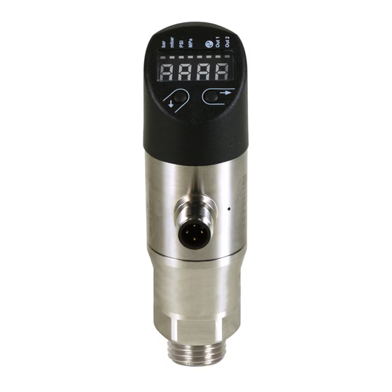
Table 2 3. Overview, functional Button function description <Content> 3.1 Display and control elements Scroll from menu 1 to menu 5, Press briefly then back to the display Fig. 1 Quickly increase a parameter Press and hold value Press briefly Select the menu item in a menu ... -
Page 9: Output Functions
Hysteresis function: The hysteresis maintains stability in the Table 3 switching of the outputs, even when the system pressure Adjustable parameters fluctuates around the setpoint. When the system pressure is rising, the output is switched when the relevant switching point <Content>... -
Page 10: Adjustable Delay
Fig. 3 Table 4 First menu level <Content> Menu 1 and Setting the switching points Menu 3 Setting of the values at which the SP 1 / SP 2 switching points 1 and 2 respectively FH 1 / FH 2 are activated. -
Page 11: Io-Link Interface
Table 5 Table 5 Second menu level Second menu level <Content> <Content> Menu 5/3 and Setting of the OFF delay Menu 5/15 Access protection Menu 5/5 Setting of the value for the OFF delay codE Setting of the password for access dr 1 / dr 2 after the switch-off point 1 or 2 is protection of the menu... - Page 12 Diagnostic capabilities Table 8 The pressure sensors have additional diagnostic capabilities that Error Codes can transmit information both via the IO-Link mode and, in part, via the display (operating hours and pressure peaks). <Content> 0x8030 Parameter value out of range •...
- Page 13 Parameter data The parameter data of the pressure sensor correspond to the Smart Sensor Profile (V1.0). Table 10 Parameter data Index Subindex Object Name Single Value Default Comments 0x02 0x00 System Commands 0x81: Delete Min/Max Value 0x82: res 0xA0: Set0 0x03 0x00 Data Storage Index...
- Page 14 Table 10 Parameter data Index Subindex Object Name Single Value Default Comments 0x03 SwitchPoint 0x0000: No Hysteresis Hysteresis 2 0x93 0x00 SwitchPoint Type 1 0x00: PNP Output 0x01: NPN Output 0x97 0x00 SwitchPoint Type 2 0x00: PNP Output 0x01: NPN Output 0x02: 0...10 V Output 0x03: 4...20 mA Output 0x50...
-
Page 15: Technical Data
4. Technical data Table 12 Technical data for pressure sensor 2340-00000108 Electrical data Mechanical data Operating voltage U 18…30 V DC Quick coupling connection M12 connector, 4-pin, A-coded Output voltage ≤ 150 mA Housing material PE, stainless steel (1.4301) Interface IO-Link V1.1... -
Page 16: Delivery, Returns, Storage
(for air bleed). • The installation must not place any mechanical stress on the pressure port, as that could cause the characteristic curve to Mounting dimensions of pressure sensor 2340-00000108 shift. This especially applies in the case of very small pressure ranges. -
Page 17: Installation Of G1/4" Adapter And M12 Socket
Fig. 6 Fig. 8 Mounting dimensions of G1/4" adapter for pressure sensor 2340-00000108 Fig. 7 Installation of G1/4" adapter and M12 socket 6.4 Aligning and rotating the display The display screen may need to be aligned, depending on the installation location and position of the pressure sensor. -
Page 18: Electrical Connection
7. First start-up The products described do not require any special procedure for initial start-up. 8. Operation SKF products operate automatically to the greatest possible extent. Basically, activities during standard operation are limited to: • Regular function checks • Regular checks for contamination or damage Display and connection enclosure 9. -
Page 19: Basics
10.1 Basics 11. Faults, causes, and Cleaning should be carried out in accordance with the operator's remedies own company rules, and cleaning agents and devices and the personal protective equipment to be used should likewise be Faults and malfunctions can be identified and remedied selected in accordance with those rules. -
Page 20: Spare Parts And Accessories
Accessories are used to extend, supplement the functional range or to assemble the product. Table 15 14.1 Pressure sensor assy Designation Pcs. Item number Figure Pressure sensor assy 2340-00000108 Including separate adapter G1/4 to EN 2852 and M12 coupling socket, 5-pin, A-coded 90° Table 16 14.2 Pressure sensor assy Designation Pcs. Item number... - Page 21 Notes...
- Page 22 ® SKF is a registered trademark of the SKF Group. ™ eLube is a trademark of the SKF Group. © SKF Group 2021 Reprint or reproduction of the contents of this information - even in part - is permitted only with SKF's prior written consent.
Need help?
Do you have a question about the 2340-00000108 and is the answer not in the manual?
Questions and answers