
Subscribe to Our Youtube Channel
Related Manuals for SKF CMSS 60


Summary of Contents for SKF CMSS 60
- Page 1 Eddy Probe Systems Technical Manual Part number: CMSS 31075800 Revision G October 2008...
-
Page 3: Table Of Contents
Table of contents Description Page Description Page Section 2 – Typical eddy probe arrangement SKF Reliability Systems Limited Warranty ......... v plans Service information .................Back Typical eddy probe arrangement plans ..........2-1 Section 1 – General information Radial shaft vibration probes ............2-3 Introduction ..................1-1... -
Page 4: Description
Table of contents Description Page Description Page Section 5 Optional equipment Section 3 – Probe installation Introduction ..................5-1 Normal motion ...................3-8 CMSS 920 High Pressure Feedthrough .........5-1 Setting gap electrically ..............3-8 Documentation...................3-8 CMSS 30112000 Series Cable Packing Gland Assembly ....5-2 CMSS 30837800 1/2”... -
Page 5: Skf Reliability Systems Limited Warranty
TWO-YEAR WARRANTY Product sold by SKF, even if such claim is based on tort (including negligence or strict liability), breach of contract, Products warranted for two (2) years by SKF are as follows: or any other legal theory. - Page 6 SKF’s sole judgment, been subjected to accident, abuse, warranty. misapplication, improper mounting or remounting, improper lubrication, improper repair or alteration, or maintenance, neglect, excessive operating conditions or for ® SKF, MARLIN, Microlog and Multilog are registered trademarks of the SKF Group. CM-F0001 (Revision P, 12-07) Limited Warranty...
-
Page 7: Section 1 - General Information
Extension • 5 mm CMSS 61/CMSS 900/CMSS 606 Series Probe Driver System length cables • 8 mm CMSS 60/CMSS 900/CMSS 600 Series CMSS 60 CMSS 900 CMSS 600 5 meters • 5 mm CMSS 65/CMSS 958/CMSS 665/CMSS 665P CMSS 60... -
Page 8: Introduction To Manual
Table 1-2. Probe compatibility. Probe CMSS 60 CMSS 61 CMSS 62 CMSS 65 CMSS 68 3/8”-24 1/4”-28 1”-12 1/4”-28 3/8”-24 Case thread (M10-1) (M8-1) (Not available) (M8-1) (M10-1) Tip diameter 8 mm 5 mm 19 mm 5 mm 8 mm... -
Page 9: Reshipment Procedure
Selecting an eddy probe system Reshipment procedure If the probe system and/or accessories must be reshipped, A wide variety of SKF systems are offered to meet the use the original shipping container and packing materials. requirements of virtually any application. Probe range is If the original packing materials are not available, the limited largely by the probe’s diameter. -
Page 10: Some Eddy Probe Options
Recommended when the cable is not protected by conduit characteristics as the shaft. The SKF CMSS 601 Series (such as inside a machine). Available on probe cables and Static Calibrator and the driver trim control, permit extension cables. - Page 11 (refer to Table 1-1). “Super tough” eddy current probe systems are thoroughly The larger tip diameter (8 mm) of the CMSS 68 SKF Eddy field tested and proven, with thousands of units installed. Current Probe is used for large diameter shafts as well as long range axial position (thrust) measurements.
-
Page 12: Operating Considerations
The type of metal of the observed surface (target material) affects the eddy current probe’s sensitivity. SKF probes are normally factory-calibrated for 4140 Steel (either factory or user can calibrate for other metals). If your target material is not 4140 Steel, the probe must... -
Page 13: Preinstallation Checklist
Pre-installation checklist Ready-to-use • Physical condition Use this section as a guide for eddy probe installation. • Cable kinked or crushed • Connector threads Make sure no other part of the system, including additional • Center pins of connector amplifiers, filters, and readout devices establish any •... - Page 14 Section 1 – General information...
-
Page 15: Description
Section 2 Typical eddy probe arrangement plans Typical eddy probe arrangement plans Figures 2-1 through 2-6 depicts sample typical eddy probe arrangements. Illustrations courtesy of API Standard 670. Item Description Item Description Input shaft coupling end Y radial vibration probe, 45° left of TDC Axial position probe (instrument Output shaft (instrument manufacturer ID data) - Page 16 Typical eddy probe arrangement plans Item Description Axial position probe (instrument manufacturer ID data) Item Description Axial position probe (instrument manufacturer ID data) Outboard end Y radial vibration probe, 45° left of TDC Inboard end radial vibration probe, 45° left of (instrument manufacturer ID data) TDC (instrument manufacturer ID data) Outboard end X radial vibration...
-
Page 17: Radial Shaft Vibration Probes
Radial shaft vibration probes Referenced such that when viewed from the driver end of the machine train, the Y (vertical) probe is on the left side of the vertical center, and the X (horizontal) probe is on the right side of the vertical center regardless of the direction of shaft rotation. -
Page 18: Bearing Housing Mounting
Bearing housing mounting CMSS 911 Assembly (Typical) 1/2” Flex Conduit “Sealtite” or Equivalent (Typical) 3/4”–1/2” Reduction Thermocouple Typical Bushing (Typical) Wire CMSS 911 Extension (Use As Required) Rotation Radial Bearing Thrust Collar Thrust Bearing Figure 2-10. End view. Figure 2-11. Side view. Notes: Notes: Drill and tap housing for 3/4”... -
Page 19: Axial Probe Installation
1/2" Conduit Hub down the machine, install spare probes Calibrate probe, cable and driver and record final response curves for primary as well as spare probes. The SKF CMSS 601 Series Static Calibrator may be used. Recommended Working Range Minimum Try to observe the thrust collar with one probe and the Thickness is 3/8”... - Page 20 Axial probe installation Axial Probe Axial Probe Phasor Probe Figure 2-13. Notes: Set sealing adapter tight in housing before pulling lead wires through. Probe lead wires must be secured against internal whipping and rubbing. Identify probe leads prior to installation. Use tag numbers as required.
-
Page 21: Section 3 - Probe Installation
See Figure 3-2. Cable Customer ID Customer Heat Shrink Figure 3-1. Typical SKF Eddy Probe. Compressor Compressor Inboard Bearing Inboard Bearing Probe tip The tip is placed in proximity to observed surface. -
Page 22: Mounting The Probe
(approximately: -8 Vdc for CMSS 61 and Probes can be mounted by threading it through a hole CMSS 65; -10 Vdc for CMSS 60 and CMSS 68; -9 Vdc for in an existing part of a machine, such as the casing, or CMSS 62). -
Page 23: Cmss 904 Probe Holder
CMSS 904 Probe Holder 1. Cut threaded extension of stinger (part 2) to desired length, deburr, and chase threads using a 1/4–28 or 3/8–24 tap. The CMSS 904 Probe Holder provides a rigid mount with provision for external gap adjustment. Conduit may be 2a. - Page 24 CMSS 911 Probe Holder with Housing/Dual Sensor Holder with Housing The CMSS 911 Probe Holder (Figure 3-7) with Housing offers an 4.44” (113mm) adjustable probe mount with a variety of penetration depths. The integral 3.50” (89mm) housing protects the probe cable exit and permits easy access for probe adjustment without machine disassembly.
-
Page 25: Cmss 911 Dual Sensor Holder
(28 mm to 60 mm) 1. Cut thread extension part 7 or (part 11) to desired 0.75” to 2.00” CMSS 912-3 3/8-24 CMSS 60/CMSS 68 (19 mm to 51 mm) length if necessary, deburr, and chase threads using a 0.95” to 5.00”... - Page 26 Installation instructions for CMSS 912 Dual Axial Probe Adapter 1. Prepare the mounting surface as C L of Shaft Bearing shown in Figure 3-11. 2. Cut threaded extension (Part 2) Figure 3-12 to desired length, deburr, and chase the threads with 1/2"...
-
Page 27: Cmss 903 Series Mounting Brackets
They eliminate the chore of making special (8mm) brackets or fixtures for each installation. They also help insure that every SKF Eddy Probe will continue to deliver all 0.88” (22mm) the accuracy built into it … year after year. -
Page 28: Installation Instructions For Cmss 903 Series Mounting
Eddy Probe Holder Holder material If the monitor system is not near the machinery, use a CMSS 60 or CMSS 68 CMSS 903-1 Aluminum voltmeter to set the gap. CMSS 61 or CMSS 65 CMSS 903-2... -
Page 29: Cables And Connections
Cables and Cable Radius (R) = 2 Inches (50.8mm) Minimum connections Coax CMSS 665 Displacement The probe and driver are always Probe Driver interconnected with the CMSS 900 or CMSS 958 Extension Cable which (To Clamp) is specifically manufactured to have Maximum Length the proper electrical characteristics. -
Page 30: Probe Mounting Don'ts
Table 3-3. Component compatibility. Eddy probe Driver (material) Extension cable Shim Stock (For Gap Adjustment) CMSS 60 CMSS 600 (Aluminum) CMSS 900 CMSS 61 CMSS 606 (Aluminum) CMSS 900 Button CMSS 62... -
Page 31: Section 4 - Driver Installation
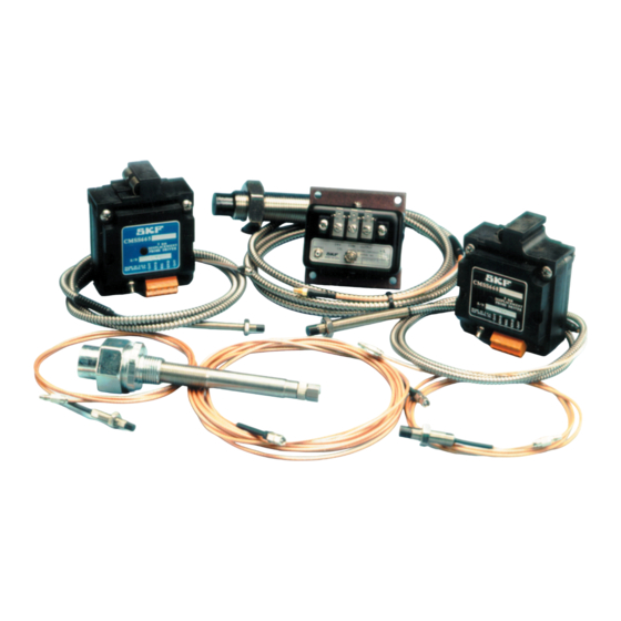
This section explains how to install SKF Eddy Probe Drivers (electrical and mechanical). Figure 4-1 shows typical SKF Eddy Probe Drivers have a power supply rejection ratio drivers. -
Page 32: Power Requirements
All the power requirements are usually supplied Gap (mils) from installed instrumentation or may be Figure 4-2. Effects of power supply voltage on linearity. supplied using SKF DIN-rail mounted power supply model CMSS 31123300. This power supply is rated at 0.175 amperes. To Monitor System... -
Page 33: Mounting (Mechanical)
Figure 4-4. Electrical and signal connections for probe drivers (CMSS 665, environments. CMSS 665P, CMSS 668 and CMSS 668P). Mounting (Mechanical) SKF drivers can be directly mounted on any stable surface like a wall or panel, through the 3.00” 3.00”... -
Page 34: Isolation Plate For Cmss 600, Cmss 606 And Cmss 620-2
• IEC 529, IP66 (European Standard) Weatherproof housings for protection from adverse environmental conditions SKF Condition Monitoring product line offers three types of housings to provide protection from adverse environmental conditions for DIN-rail mountable eddy probe drivers. Water resistant housing... -
Page 35: Weatherproof Housings For Din-Rail Mount Drivers
• CMSS 31092200 Weatherproof housing for maximum six drivers Table 4-2. Weatherproof housing dimensions. • CMSS 31092300 Weatherproof housing for maximum ten drivers SKF model Box size Mounting Clamp style Hinge style Area classification — (Stainless steel, clamp number A x B x C... - Page 36 The drivers can be mounted inside the housing on ordinary steel “Type C DIN-rails” available from SKF. There are 1.31” (33mm) two sizes, 9” (225 mm) and 15” (375 mm) lengths. Use part number CMSS 31093101 and CMSS 31093100 respectively.
-
Page 37: Explosion-Proof Housings For Din-Rail Mount Drivers
Explosion-proof housings for Explosion-proof housing DIN-rail mount drivers dimensions Explosion-proof housings 7.875" (197mm) • Explosion-proof and dust-tight housings 6.375" (159mm) • Class I, Group C and D • Class II, Groups E, F, and G 7.875" (197mm) • Class III, 6.375"... -
Page 38: Explosion-Proof Housings Dimensions
The drivers can be mounted inside the housing on ordinary Figure 4-16 shows the minimum clearances needed to steel “Type C DIN-rails” which is available from almost any install the drivers in explosion-proof housings. These electrical supply outlet. clearances allow for the cables and for the “swing” involved in snapping the driver clip into the DIN-rail. -
Page 39: Section 5 Optional Equipment
(31.8mm) (38.1mm) 3/4" (19.0mm) NPT Both Ends Armor Optional Armor Optional This section explains some of the options used with SKF Eddy Probe Systems. Cable 1 High Pressure End Length CMSS 920 High Pressure Cable 2/3 High Pressure End Length... -
Page 40: Cmss 30112000 Series Cable Packing Gland Assembly
CMSS 30112000 Series Cable Packing Gland Assembly Low Pressure (LP) High Pressure (HP) The CMSS 30112000 Series Cable Packing Gland Assembly offers a splash-proof cable exit from the machine case. They are available in 1 or 2 cable exit versions and Machine Case with either a 1/2”... -
Page 41: Cmss 30837800 1/2" (12.7 Mm) Or 3/4" (19 Mm) Npt
CMSS 30837800 1/2” (12.7 mm) or 3/4” (19 mm) NPT Probe Adapter The probe adapter is used to mount a probe with a 1/4–28 or 3/8–24 thread in a machine case which will accept the 1/2” (12.7 mm) or 3/4” (19 mm) NPT fitting. Conduit or a junction box may be mounted on the exterior side of the adapter. - Page 42 Section 5 – Optional equipment...
-
Page 43: Section 6 Maintenance
CMSS 60, CMSS 61, CMSS 65, or CMSS 68 Series Eddy Probes. The CMSS 601-1 measures the gap Periodic/preventative in milli-inches (mil) and the CMSS 601-2 and CMSS 601-8 measures in micrometers. -
Page 44: Procedure
CMSS 958 Extension Cable and connect the extension cable to the appropriate probe driver (CMSS 600 Driver for CMSS 60 Series Probes, CMSS 606 Driver for CMSS 61 Series Probes, CMSS 665 Driver for CMSS 65 Series Probes, CMSS 668 Driver for CMSS 68 Series Probes). -
Page 45: Cmss 601-8 Field Calibrator Set-Up Procedure
Screw the appropriate disc-shaped probe adapter D, onto the probe E. There is one disk adapter for the CMSS 60/CMSS 65 Probes and one for the CMSS 61/ CMSS 68 Probes. Insert probe tip carefully through center hole in magnet F, until adapter clamps to magnet. -
Page 46: Calibration Procedure
Calibration procedure If slight adjustment of the slope is necessary to calibrate to a particular shaft material, the CALIB (calibrate) Slowly adjust the micrometer dial, first increasing and control on the eddy probe driver unit provides a ±10% then decreasing from the 40 mil (1 mm) starting gap, adjustment for sensitivity. -
Page 47: Probe Gap Voltage Test Setup
Repairs • To gap a CMSS 68-xxx-xx-xx-10 Probe, use a CMSS 958-xx-040 Extension Cable and a CMSS 668 Eddy current probes produced by SKF are not normally Driver. repairable except for the end connector. • To gap a probe at 40 mils (1.0 mm), adjust the probe for Caution: Do not repair probe cables or extension cables by a -8.00 volt reading on the digital voltmeter. - Page 48 SKF reserves the right to alter any part of this publication without prior notice.
Need help?
Do you have a question about the CMSS 60 and is the answer not in the manual?
Questions and answers