
Related Manuals for ROBEL ROGRIND E3 13.49HSK


Summary of Contents for ROBEL ROGRIND E3 13.49HSK
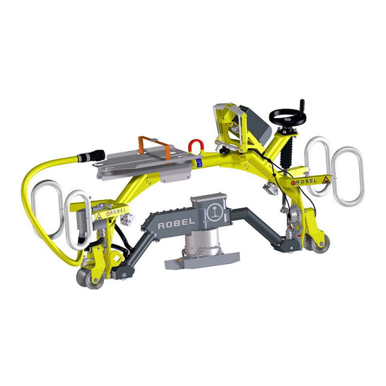
- Page 1 Content OPERATING MANUAL ROGRIND E 13.49HSK Model 3 Hybrid Rail Head Profile Grinding Machine 13.49 Vers. 3...
- Page 2 Translation of Original Operating Manual Status: 27.07.2022 Version: V1 © 2022 ROBEL Bahnbaumaschinen GmbH These operating instructions were produced in accordance with the current state of technology at the time of printing. The right to change on the basis of further developments is reserved.
-
Page 3: Table Of Contents
Content Content General ....................7 About these instructions........7 General Regulations.......... 7 Intended Audience for this Operating Manual ... 8 Liability Exclusions..........8 Copyright ............9 Acceptance, Equipment and Operating Licence ..9 Validity of these instructions ........ - Page 4 Content Description of machine ................23 Overview ............23 Control elements..........25 4.2.1 Dead man’s brake ............25 4.2.2 Control system (PLC) ..........26 4.2.3 Tilt adjustment handwheel ......... 27 4.2.4 Grinding depth infeed ..........27 4.2.5 Track width adjustment ..........
- Page 5 Content Putting the machine into operation ..............37 Re-railing ............. 37 6.1.1 Preparing the machine ..........41 6.1.2 Place the machine on the track........41 6.1.3 Mounting the outrigger..........44 6.1.4 Retracting the handles ..........45 6.1.5 Adjusting the track width of the outrigger....46 Checking the machine ........
- Page 6 Content Maintenance .................... 82 Maintenance schedule ........83 Changing the abrasive ........84 8.2.1 Preparing the machine ..........84 8.2.2 Moving into change position ........85 8.2.3 Changing the abrasive ..........90 Servicing the dead man’s brake ......93 Lubrication ........
-
Page 7: General
ROBEL Bahnbaumaschinen GmbH together with its customer service organizations are however happy to provide further advice, training or other consultative services. Further details and conditions can be obtained separately. -
Page 8: Intended Audience For This Operating Manual
1. General Intended Audience for this Operating Manual This operating manual contains important information for the intended use of the product described therein. The manual has been written exclusively for technically quali- fied personnel. Qualified personnel in this context are: •... -
Page 9: Copyright
Specific characteristics and particular attributes of the ma- chine are the intellectual property of ROBEL Bahnbaumaschi- nen GmbH. The copyright on its use remains with ROBEL Bahnbaumaschinen GmbH. It may not be reproduced either in full or in part, published or otherwise exploited for competitive purposes, whether for payment or not. -
Page 10: Safety
2. Safety Safety Designated use The rail head profile grinding machine 13.49HSK Model 3 is designed and manufactured for the grinding of rails with a high degree of contour accuracy. The machine is designed and constructed solely for the accu- rate manual grinding of weld joints, running surfaces, rail head gauge corners and rail head sides of steel rails with a Vignole profile without the use of cooling lubricants. -
Page 11: Conventions Of Layout
2. Safety Conventions of layout This operating manual uses the following warning phrases and symbols to ensure the personal safety and physical integrity of the user and to protect the assets of the operator from dam- age: DANGER Indicates that non-observance of the instruc- tions results in death or severe injury of the operator. -
Page 12: Design Changes, Original Parts
2. Safety Structure of the warnings The warnings are structured as follows: SIGNAL WORD Type and source of danger! Possible consequences when ignoring the danger. ► Measure to avoid the danger. Design changes, original parts The manufacturer accepts no liability for unauthorised modifi- cations to components and attachments to the product. -
Page 13: Safety Regulations
2. Safety Safety regulations The handling requirements necessary for the protection of life, health, property and the environment must be ensured as a matter of priority. ► Before using the device, make sure you can prove that all personnel affected have been made aware of the following relevant regulations and provisions: statutory safety regulations •... -
Page 14: Personal Protective Equipment
2. Safety Personal Protective Equipment Use the approved PPE during the operation and maintenance of the product. ► Wear protective gloves. ► Wear steel-capped work shoes. ► Wear a protective helmet. ► Wear suitable hearing protection for high- frequency noise. ►... -
Page 15: Instructions For Particular Types Of Hazards
2. Safety Instructions for particular types of hazards Danger due to manual If the permissible per-person lifting weight is exceeded when handling lifting or carrying, there is a risk of injuring muscles, tendons, joints or bones. ► Prior to transportation, ensure that the pathway is free of obstructions or trip hazards. - Page 16 2. Safety Danger due to unergonomic With some activities there is a risk of injuring muscles, ten- operation dons, joints or bones if the necessary caution is not exercised with the controls. An example is starting the engine by means of the reversing starter.
- Page 17 2. Safety Dangers from heat Risk of injury from touching hot parts. ► Do not touch hot parts. ► Prior to work on heated parts, switch off the machine allow to cool down for at least 30 minutes. Fire hazard ►...
-
Page 18: Accident Prevention
2. Safety 2.10 Accident prevention The accident prevention regulations of the Civil Engineering association also find application in these operating instructions and are to be carefully read and adhered to. ► Always observe the general and internal accident preven- tion regulations. ►... -
Page 19: First Aid
2. Safety 2.11 First Aid Please ensure the following to be able to provide First Aid in an emergency: ► Make sure that the First Aid kit is in proper condition, com- plete and clean at all times. ► Consult the medical service or doctor at your office regard- ing First Aid measures and appropriate equipment. -
Page 20: Technical Data
3. Technical data Technical data Drive Electric motor (synchronous motor) Nominal voltage 56 V Nominal current 60 A Rated power 3 kW Energy supply The machine can be operated with the following energy sources: • ROPOWER Hybrid Drive Unit 70.02 •... -
Page 21: Abrasives
3. Technical data Abrasives Bonded grit abrasives for rail head widths up to 120 mm. These abrasive discs must be ordered separately. Cup wheel Outer diameter 150 mm Inner diameter 55 mm Height 60 mm Maximum permissible speed 6,350 rpm Weight 2.5 kg Plunging depth... -
Page 22: Operating Conditions
3. Technical data Operating conditions Temperature range operation -10°C to 40°C Temperature range transport -20°C to 50°C Temperature range storage -20°C to 50°C 3.10 Brake test Brake tests have been carried out. Slope angle Braking distance 4.00 degrees Rail wet: 5 m 4.00 degrees Rail dry: 4 m 13.49 Vers. -
Page 23: Description Of Machine
4. Description of machine Description of machine Overview The practical design offers the following features: Powerful drive motor • possibilities of energy supply • ROPOWER Hybrid Drive Unit 70.02 – ROPOWER Power supply 70.03 – ROBATTERY 71.02 (2,300 Wh) – PLC for simple operation •... - Page 24 4. Description of machine Support roller with battery powered lighting (option: re- chargeable battery) Fig. 2: Support roller of extension arm (Option „Reflector“) Clamp screw Support roller Extension arm Handle A special version of the supporting roller mount can be ordered which enables the attachment of rear lights.
-
Page 25: Control Elements
4. Description of machine Control elements 4.2.1 Dead man’s brake WARNING Risk of accidents! An unbraked machine can reach high speeds on inclines. It can result in collisions with peo- ple and rail vehicles. ► Always test the function of the dead man’s brake before using the machine. -
Page 26: Control System (Plc)
4. Description of machine 4.2.2 Control system (PLC) Fig. 4: Control system (PLC) Display Button „4“ Button „Enter“ Button „ESC“ Button „3“ Brightness sensor LED green/red Button “2“ Motor stop button Button „1“ The PLC is used to control every electrical feature. The PLC is starting as soon as electrical power is provided. -
Page 27: Tilt Adjustment Handwheel
4. Description of machine 4.2.3 Tilt adjustment handwheel Fig. 5: Tilt adjustment handwheel Turn the handwheel clockwise to tilt the swivel frame to • the right as seen from the user’s standpoint. Turn the handwheel anticlockwise to tilt the swivel frame •... -
Page 28: Track Width Adjustment
4. Description of machine 4.2.5 Track width adjustment Fig. 7: Support roller of extension arm (Option „Reflector“) Clamp screw Support roller Extension arm Handle The support roller can be moved along the axis of the outrigger. 4.2.6 Motor stop button The machine is equipped with an motor stop button. - Page 29 4. Description of machine 4.2.7 Holder for battery or converter With the help of a lashing strap, the battery or the converter is securely fastened to the holder. Fig. 9: Holder with battery Fig. 10: Holder with converter 13.49 Vers. 3...
-
Page 30: Safety Device
4. Description of machine Safety device Guard plates are attached to both sides of the grinding spindle. Fig. 11: Guard plates Accessory (available to order) Cup wheels Fig. 12: Ø 150 mm 4.4.1 Extension set for battery or mains operation he extension set contains all the adapter cables required to operate the machine with a battery or a converter. -
Page 31: Signs And Labels
4. Description of machine Signs and labels 4.5.1 Signs and labels used Fig. 13: Label "Instructed person- Fig. 14: Label "Observe operating nel only" instruction" Fig. 15: Label "Grinding Wheel diameter = 150 mm, MAX RPM = 5500 and Direction of rotation " Fig. - Page 32 4. Description of machine Fig. 20: Label "Crushing hazard" Fig. 21: Label "EN 13977" Fig. 22: Label "Lift here" Fig. 23: Label "High Voltage" Fig. 24: Label "Logo of manufac- Weight and lift Fig. 25: Label " turer" with two person "...
-
Page 33: Position On The Machine
4. Description of machine 4.5.2 Position on the machine Right side Fig. 26: Right side Label “Crushing hazard” Label “Logo of manufacturer” Label “EN13977” Identification plate Label “High Voltage” Label “Lift here” Label “Instructed personnel only” Label “Observe operating instructions” Label “Wear protective gloves”... -
Page 34: Work Place
4. Description of machine L eft Side Fig. 27: Left side Label “Lift here” Label “Logo of manufacturer” Label “Crushing hazard” Work place The guide handle is for guiding the machine along the rail. Ide- ally, the user should stand between the rails of the permanent way holding the guide handle with both hands, or where nec- essary, with one hand on the guide handle and the other on the handwheel to adjust the tilt. -
Page 35: Structure Gauge
4. Description of machine Structure gauge While the rails are being processed, a violation of the structure gauge in accordance with DIN EN 15277-2 cannot be excluded, because the user may have to stand beside the track to carry out side grinding as described in chap. 4.6. Fig. - Page 36 4. Description of machine Fig. 29: Structural gauge (left) 13.49 Vers. 3...
-
Page 37: Operating Conditions
5. Operating conditions Operating conditions Operating WARNING Risk to life from electric shocks! Exposure to very strong sunshine can heat the apparatus to well over +70°C. If as a result the outer casing becomes distorted, electrical safety may well be compromised. ►... - Page 38 5. Operating conditions Abrasives NOTICE Risk of damage! Abrasives become unusable when they become damp or come in contact with grease and oil. ► Store the abrasives in a dry place, making sure they do not come in contact with moisture, oil or grease. 1.
-
Page 39: Transport
5. Operating conditions Transport WARNING Risk of injury! The machine is too heavy for one person alone. An injury to the muscles, bones or ten- dons may result, particularly those in the back and shoulders. ► Always transport the machine with suita- ble equipment, e.g. -
Page 40: Retracting The Handles
5. Operating conditions NOTICE Risk of loosing the disc Transporting the machine without the abrasive (2) mounted, the grinding stone flange (1) may fall out and can be lost. ► Transport the machine with mounted abrasive only. Fig. 31: Abrasive dismantled Grinding stone flange Abrasive 5.3.1 Retracting the handles... -
Page 41: Putting The Machine Into Operation
6. Putting the machine into operation Putting the machine into operation Re-railing 6.1.1 Preparing the machine NOTICE Risk of damaging the abrasives! If the abrasive is outside the protective hood it can be easily damaged when being put on to the rail. ►... - Page 42 6. Putting the machine into operation Dismantle the outrigger 1. Loosen clamping screw (3). 2. Remove the outrigger (1) from the socket (4). Fig. 33: Plug in outrigger Outrigger Stop Clamping screw Socket 3. Put the swivel frame into a vertical position using the tilt adjustment handwheel.
-
Page 43: Place The Machine On The Track
6. Putting the machine into operation 6.1.2 Place the machine on the track WARNING Risk of injury! The machine is too heavy for one person alone. An injury to the muscles, bones or ten- dons may result, particularly those in the back and shoulders. -
Page 44: Mounting The Outrigger
6. Putting the machine into operation 6.1.3 Mounting the outrigger. 1. Ensure that the clamping screw (3) is not protruding, else the outrigger cannot be inserted. 2. Insert the outrigger (1) into the socket (4) and push in up to the stop (2). -
Page 45: Retracting The Handles
6. Putting the machine into operation Fig. 38: Engage fastener 3. Fasten clamping screw (1) clockwise by hand. 4. Perform small movements (“toggle”) of the star knob (1) during final tightening so that the contact surfaces (2) are aligned and can build up grip without residual play The outrigger has been mounted. -
Page 46: Adjusting The Track Width Of The Outrigger
6. Putting the machine into operation 6.1.5 Adjusting the track width of the outrigger Fig. 40: Support roller of extension arm (Option „Reflector“) Clamping screw Support roller Outrigger Handle 1. Loosen clamping screw (1). 2. Slide the support roller (2) along the outrigger (3) with the aid of the handle (4). - Page 47 6. Putting the machine into operation 6.1.6 Mount battery or converter The holder for the battery or converter consists of two alumini- um shells that are mounted on the machine. With the help of a lashing strap, the battery or the converter is securely fastened to the holder.
-
Page 48: Checking The Machine
6. Putting the machine into operation Checking the machine 6.2.1 Grinding spindle and abrasive WARNING Risk of injury! Abrasives whose use-by date has expired or abrasives with dents or cracks can burst dur- ing operation! Fragments can fly everywhere and cause serious injuries. ►... -
Page 49: Electric Motor
6. Putting the machine into operation 6.2.2 Electric motor WARNING Risk to life from electric shocks! Defective or loose cable connections and ca- ble connections that are not properly plugged in can cause fatal electric shocks if they are touched. ►... - Page 50 6. Putting the machine into operation Fig. 44: Close the bracket Fig. 45: Bracket closed Fig. 46: Close the lock 13.49 Vers. 3...
- Page 51 6. Putting the machine into operation Fig. 47: Connector locked Use adapter cable when used with ROBATTERY 72.02. 13.49 Vers. 3...
- Page 52 6. Putting the machine into operation NOTICE Risk of damage! If the cable is left dangling over the rail, it might be rolled over during work. ► Thread the power supply cable through one of the carry- ing handles, see pictures below. Fig.
-
Page 53: Dead Man's Brake
6. Putting the machine into operation 6.2.3 Dead man’s brake The machine must not be braked while the dead man’s brake lever is not actuated. WARNING Risk of accident! An unbraked machine can reach high speeds on inclines. It can result in collisions with peo- ple and rail vehicles. -
Page 54: Starting The Plc
6. Putting the machine into operation Starting the PLC 1. Connect the machine to the energy source used. Connect the machine to the Hybrid Drive Unit and start the • Hybrid Drive Unit Mount the converter on the bracket and establish electrical •... -
Page 55: Operating The Plc
6. Putting the machine into operation Operating the PLC Main menu Fig. 51: Main menu Display of actual Infeed depth of abrasive Display of actual voltage ‘switch symbol’ button ‘Zeroing’ button ‘Illumination’ button Button function Switch symbol Switch the motor on/off (Switching on needs confirmation with "Enter"... -
Page 56: Switch On Illumination
6. Putting the machine into operation 6.5.1 Switch on illumination There are two laps on the machine, one at the front (left) and one at the back (right). Both lamps are switched with the but- ton "1" (with lamp symbol) on the PLC. Initial condition: both lamps are switched off, the lamp symbol is highlighted in grey (see following picture) Fig. - Page 57 6. Putting the machine into operation 6.5.2 Feinschliffprogramm Während der Schleifbearbeitung nutzt sich das Schleifmittel ab. Dieser Verschleiß muss beim Feinschliff ausgeglichen wer- den. 5. Die Taste mit dem Zustellsymbol drücken. Abb. 53: Zustelltiefe 0,25 Die Zustelltiefe ist auf den Wert „0,25“ eingestellt. 6.
-
Page 58: Setting The Zero Point
6. Putting the machine into operation 6.5.3 Setting the zero point There are two operating modes: Standard When the mode "Standard" is activated, the infeed depth can be moved up and down with the ‘Retract’ and ‘Infeed’ buttons. Controlled depth When the mode "Controlled depth"... - Page 59 6. Putting the machine into operation Call up the ‘settings’ Menu 1. Press the ‘ESC’ button. The following menu appears. Fig. 54: Display „Grindingstone change position” 2. Press both soft keys under the outer keys ("1" and "4", marked "X" in the picture) simultaneously. The "Settings"...
-
Page 60: Stepper Manually
6. Putting the machine into operation 6.6.1 Stepper manually This option is needed in case the infeed drive is blocked and the movement of the infeed drive shall be possible without the restriction of software end-stops. Fig. 56: "Stepper manually" 1. -
Page 61: Put Into Service
6. Putting the machine into operation 6.6.2 Put into service This option can only be accessed by start-up engineers (ROBEL staff), the message "No authority for the next step" appears. Fig. 57: Message „No authority“ 6.6.3 Debugging Use this option in order to get additional status information for error tracking. - Page 62 6. Putting the machine into operation Fig. 59: Debugging-information for Stepper Command Response PLC Approval Down Depth stop Tool change Use this menu in order to check whether the signals of operat- ing buttons or sensors are reaching the PLC or not. The following gives an example, how the debugging procedure is meant to be carried out.
- Page 63 6. Putting the machine into operation If the button is working, the circle before “Down” will be green, see following screen: Fig. 60: Button “Down” pressed and registered The button is working properly. In the right column “Response”, the circle before “Down” is also highlighted green.
-
Page 64: Service
6. Putting the machine into operation 6.6.4 Service In this menu the operating hours and the remaining time until the next service is displayed. Figures in red and with “-“ indicate that maintenance has been exceeded. Fig. 61: Service Information Reset service interval 1. - Page 65 6. Putting the machine into operation Reset to factory settings 1. Press the soft key below “Factory settings”. A query appears as to whether the factory settings are definitely to be reinstated. Fig. 62: Confirm with ENTER 2. Press “Enter”. The factory settings of the PLC are reinstated.
-
Page 66: Brightness
6. Putting the machine into operation 6.6.5 Brightness Fig. 63: Brightness level 1. Set the desired brightness using the "-" and "+" keys. 2. Select the "Automatic brightness" option (symbol "A" at bottom right of picture). Fig. 64: Option: Automatic brightness The brightness is adjusted automatically by the bright- ness sensor on the PLC. -
Page 67: Date/Hour
6. Putting the machine into operation 6.6.6 Date/Hour The following screen appears: Fig. 65: Date and time 1. In order to change the settings, press the characters "CDDC" (code). 13.49 Vers. 3... - Page 68 6. Putting the machine into operation The following screen appears: Fig. 66: Date and time settings Date Time Central European summer time Mexican summer time North American summer time Operating hours Total Current Set date, time and choose a summer time according to the time zone.
-
Page 69: Country Settings
6. Putting the machine into operation 6.6.7 Country settings Fig. 67: Country settings 1. Use the arrow keys to select the desired country setting. 2. Press the "Enter" key. The country setting is set. 6.6.8 Contact Fig. 68: Contact information manufacturer 13.49 Vers. -
Page 70: Starting The Motor
6. Putting the machine into operation Starting the motor WARNING Risk of accident! Risk of catching or abrasion if the abrasive is touched while the motor is starting. ► Do not reach into the danger zone. ► Be aware that the abrasive starts turning as soon as the motor starts (even during the starting process). -
Page 71: Test Run
6. Putting the machine into operation Test run CAUTION Risk of injury! If the operator pulls the guide handle towards himself when guiding the machine, it may tip over. Risk of bruises and skin abrasion. ► Do not apply a force that rotates the ma- chine in the direction away from the out- rigger (see blue arrow in figure below). - Page 72 6. Putting the machine into operation 5. If the abrasive is not running properly, stop the motor im- mediately (emergency stop button). The machine may only be used if the abrasive is run- ning perfectly (no wobbling, no non-circular running, no scraping noises).
-
Page 73: Working With The Machine
6. Putting the machine into operation Working with the machine 6.9.1 General Information on the grinding process The weight of the machine is already putting a significant amount of grinding pressure on the abrasive. If additional load is put on the machine or the infeed depth is too much, this will result in a reduction of spindle RPM and several warn- ings appear on the PLC screen. -
Page 74: Grinding Vignole Rails
6. Putting the machine into operation 6.9.2 Grinding Vignole rails The machine is tailored to the required grinding pressure through its self-weight. During the grinding of the sides of the rail head the machine is pulled on to the rail by the guide discs, thus generating the required grinding pressure. - Page 75 6. Putting the machine into operation Fig. 72: Grinding infeed button ‘Retract’ button ‘Infeed’ button In the standard mode the infeed is adjusted via the buttons (1) and (2). Coarse grinding (warm) 1. Deactivate the dead man’s brake (pull the dead man’s handle in the direction of the handle).
-
Page 76: Evaluate The Grinding Pattern
6. Putting the machine into operation 2. Lower the abrasive with the electric height adjustment ex- tremely carefully and slowly until the first sparks appear when the motor is running. 3. Set the zero point and activate “controlled depth” mode (see chap. -
Page 77: Switching Off The Engine
6. Putting the machine into operation 6.10 Switching off the engine Do not stop the engine of the grinding ma- chine with the motor stop button. Using this button will also stop the Honda engine of the Hybrid Drive Unit 70.02. Use the motor stop button only in an emer- gency. -
Page 78: Unrailing The Machine
6. Putting the machine into operation 6.11 Unrailing the machine 6.11.1 Preparing the machine 1. Put the swivel frame into a vertical position using the tilt adjustment handwheel. Separate connectors 2. Disconnect the machine from the energy source used, refer to chapter 6.2.2 (in reverse order): Stop the Hybrid Drive Unit and disconnect electrical con- •... -
Page 79: Dismantling The Outrigger
6. Putting the machine into operation Pull out the carrying handles 4. Turn the star knobs counter-clockwise. Fig. 76: Pull out carrying handles (image shows ergonomically opti- mized handles) Star knobs Carrying handles 5. Pull out the carrying handles so that you can comfortably stand between them. -
Page 80: Lifting The Machine Off The Rail
6. Putting the machine into operation 6.11.3 Lifting the machine off the rail WARNING Risk of injury! The machine is too heavy for one person alone. An injury to the muscles, bones or ten- dons may result, particularly those in the back and shoulders. -
Page 81: Connecting The Electric Motor
7. Connecting the electric motor Connecting the electric motor WARNING Risk to life from electric shocks! Machine parts can carry a lethal voltage through exposed or damaged cables and elec- trical components. ► Ensure that the machine is shut down properly to prevent damage to the electri- cal parts or the whole machine. -
Page 82: Maintenance
8. Maintenance Maintenance WARNING Risk to life from electric s hock a nd u ncon- trolled starting! The machine can start at any moment, if a button is accidentally pressed during mainte- nance work. ► Before commencing all maintenance work, switch off the machine, disconnect the power supply and secure against acci- dental restarting. -
Page 83: Maintenance Schedule
8. Maintenance Maintenance schedule 1. To determine the service intervals, evaluate the operating hours counter. Interval C omponent Maintenance work Each time Dead man’s Service and check function, see chap. 6.2.3 before com- brake missioning Initially after Pivot bearing Lubricate, see chap. 8.4.1 20 operating (2x) hours, then:... -
Page 84: Changing The Abrasive
8. Maintenance Changing the abrasive 8.2.1 Preparing the machine The machine is equipped with an M20 mount to accept abra- sives with M20 thread. 1. Store the grinding machine on a clean, level and smooth surface and secure to prevent falling over. On a level surface 2. -
Page 85: Moving Into Change Position
8. Maintenance 8.2.2 Moving into change position If the travel measurement of the infeed drive is not referenced, follow the referencing pro- cedure described in chapter 6.6.1. 1. Make sure that the abrasive can travel without obstruction full way up and down. 2. - Page 86 8. Maintenance Fig. 81: Message“ Drive the stone with the Button UP to the Top posi- tion“ 5. Make sure that the abrasive is in the fully retracted posi- tion: the rim of the fan propeller must be visible through the orifice on the side oft he spindle housing (see arrow in the following figure).
- Page 87 8. Maintenance Rim of fan propeller visible 1. If the rim of the fan propeller is visible, confirm by pressing “Enter”. 2. Follow the procedure for changing the abrasive as de- scribed in chapter 8.2.3. Rim of fan propeller 1. If the automatic homing procedure was not successful, not visible.
- Page 88 8. Maintenance L oud rattle, no movement Very likely the spindle drive is blocked. possible 1. Press the “No” button or the “High Power” button. Fig. 84: Option „High Power“ For approx. 20 seconds, increased torque is available for the spindle drive. The option “High Power” is high- lighted in green.
- Page 89 8. Maintenance 7. Lift up spark protection. Fig. 85: Lift up spark protection (both sides) 8. Follow the procedure for changing the abrasive as de- scribed in chapter 8.2.3. If it is still not possible to move the abrasive despite the option “High Power” is activated, follow the procedure to manually unblock the spindle as described in chapter 9.3.
-
Page 90: Changing The Abrasive
8. Maintenance 8.2.3 Changing the abrasive WARNING Risk of severe injury! Risk of severe injury of hand and fingers if abrasive starts to rotate unintentionally. ► Stop engine of Hybrid Drive Unit and dis- connect cable before changing the abra- sive. - Page 91 8. Maintenance Fig. 87: Swivel frame at 90° 4. Turn the abrasive by hand into the proper position: A notch in the rim of the fan propeller must be visible (dark). Fig. 88: Rim of fan propeller visible (left) and notch visible (right) 5.
- Page 92 8. Maintenance 6. Unscrew the abrasive with a SW30 spanner. Fig. 90: Unscrew the abrasive 7. Pull off the abrasive (2), making sure to retain the disc (1). Fig. 91: Pull off abrasive 8. Check the new abrasive (visual inspection), insert the abra- sive and slide the disc on to the shaft.
-
Page 93: Servicing The Dead Man's Brake
8. Maintenance Servicing the dead man’s brake 1. Oil the Bowden cables and maintain smooth running. 2. Check the pins that engage the orifices in the wheels and the orifices in the rolls. Carry out brake test 1. Try to push the machine along the rail while the dead man’s brake is not actuated. -
Page 94: Gear Wheels
8. Maintenance 8.4.2 Gear wheels 1. Clean teeth from grinding dust before greasing the gear wheels. Gear wheels operator’s side Fig. 94: Lubrication point gear wheels swivel mechanism (operator’s side) Lubrication point 1 Lubrication point 2 Gear wheels front side Fig. -
Page 95: Grinding Spindle Infeed
8. Maintenance 8.4.3 Grinding spindle infeed NOTICE Risk of damage! The electric motor will be damaged if these lubrication points are greased too generously. ► Only pump the grease gun a half stroke! 1. Lubricate the grinding spindle every 100 operating hours. Fig. -
Page 96: Grinding Spindle
8. Maintenance 8.4.5 Grinding spindle Re-grease the grinding spindle every 50 operating hours. 1. Using the “infeed” button, drive abrasive to the tool change position (fully retracted, see chap. 8.2.2.) 2. Move abrasive even further up by hand. Fig. 98: Remove Hexagon screw Allen screw Allen key Rotation lock... - Page 97 8. Maintenance 5. Use a spray can (high performance, temperature resistant lubricant, e. g. CRC MULTILUBE PRO high performance ad- hesive lubricant 32697-AA). At a 45° angle, spray for ap- prox. 1 second down to the grinding spindle. Fig. 100: Lubricate grinding spindle 6.
-
Page 98: Cleaning And Care
8. Maintenance Cleaning and care NOTICE Risk of damage The use of solvents, aggressive or combustible cleaning agents can result in damage. The use of high-pressure washers can result in damage caused by water getting into the motor and articulated joints of the machine. -
Page 99: Troubleshooting
Voltage of super capacitors is duce load on spindle switched off) lower than 38,0V ► Switch off motor of Hybrid Volt >59.0V Voltage of super capacitors is Drive Unit 70.02 immediately, higher than 59.0V charge controller defective, contact ROBEL service. 13.49 Vers. 3... -
Page 100: Display Remains Dark
3. Check if ribbon cable is properly connected. If the display remains dark, it is very likely that either the display or the PLC main board is defective. 4. Change defective parts or contact ROBEL after-sales ser- vice. 9.2.2 LED is not illuminated If the LED is not illuminated, the PLC is not supplied with volt- age. -
Page 101: Unblock Infeed Drive
9. Troubleshooting Unblock infeed drive If the drive of the infeed is not responding to the actuating but- tons or when a loud rattle can be heard, the drive is blocked. This might be the case if - e.g. during maintenance work on the infeed drive –... -
Page 102: Check Chain Tension
9. Troubleshooting 9.3.2 Check chain tension 1. Press sideways against the chain (see arrow) Fig. 102: Check chain tension The chain tension is correct if it is possible to shift the chain about 1 mm. 2. If the chain is too tight, adjust chain tension. 9.3.3 Adjust chain tension 1. -
Page 103: Perform A Reference Run On The Depth Infeed
9. Troubleshooting 5. Ensure that the drive is not blocked, unblock if necessary. 6. Clean cover plate and O-ring groove, insert a new O-ring. 7. Replace cover and tighten screws. 8. Perform a reference run on the depth infeed. 9. Put the machine into service again. 9.3.4 Perform a reference run on the depth infeed 1. -
Page 104: Environmental Protection And Disposal
10. Environmental protection and disposal Environmental protection and disposal 10.1 Environmental protection While working on or with the product, comply with the legal • regulations for waste prevention and proper recycling/ dis- posal and also follow the environmental laws applicable in the user country. -
Page 105: Appendix
11. Appendix Appendix EC Declaration of Conformity Fig. 104: EC Declaration of Conformity 13.49 Vers. 3...
Need help?
Do you have a question about the ROGRIND E3 13.49HSK and is the answer not in the manual?
Questions and answers