Table of Contents
Advertisement
Quick Links
Advertisement
Table of Contents

Related Manuals for Storz NPU 408000 01


Summary of Contents for Storz NPU 408000 01
- Page 1 Instruction Manual Navigation Panel Unit NPU 408000 01...
-
Page 2: Important Information
KARL STORZ instruments Thank you for your expression of confidence in the KARL STORZ brand name. Like all of our other products, this product is the result of years of experience and great care in manufacture. You and your organization have decided in favor of a modern, high-quality item of equipment from KARL STORZ. -
Page 3: Illustrated Description
Illustrated Description... -
Page 4: Controls, Displays, Connectors And Their Uses
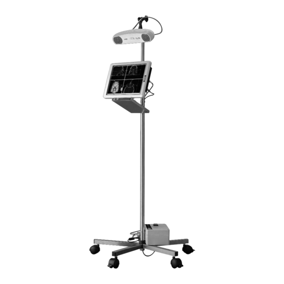
Controls, Displays, Connectors And Their Uses Handle screw for securing the jointed arm Camera Camera lenses NPU panel Docking adaptor Button for opening the CD drawer CD/DVD drive Stand bar with cable channel Stand base Power switch for turning the electronics box on and off Electronics box VGA connection for external monitor Connection for camera cable... -
Page 5: Table Of Contents
Locking the KARL STORZ NPU panel on the docking adaptor Removing the NPU panel on the docking adaptor Routing the cable of the KARL STORZ NPU panel to the electronics box Connecting the cable to the docking adaptor Connecting the cable on the electronics box... - Page 6 Starting the software Loading the planning data Starting the navigation Preparing the patient and the instruments Using sterile drapes to cover the KARL STORZ NPU Preparing the probe Preparing the patient tracker Securing the patient tracker to the patient Preparing the operating pen and/or mouse...
- Page 7 Standard compliance Directive compliance Directive compliance Disposal Disposal Cleaning agents and disinfectants Cleaning agents and disinfectants Electromagnetic compatibility (EMC) information for KARL STORZ NPU S\system Electromagnetic compatibility (EMC) information for KARL STORZ NPU S\system System Shipping Shipping Return Policy Return Policy...
-
Page 8: Intended Use
• The KARL STORZ NPU system must never be used if there are clinical or medical reasons which prevent this. • The KARL STORZ NPU system may only be used if the operation could also be performed in the conventional manner. • The KARL STORZ NPU system must not be used on patients with Creutzfeldt-Jakob disease. -
Page 9: User Qualification
• MDD 93/42/EEC: Annex I Clause 13.6.c) User qualification The user of the KARL STORZ NPU system as well as the surgical nurses and other staff must have received authorized training on the safe and effective use of the system from the manufacturer and distributor in order to be allowed to use the KARL STORZ NPU system on... -
Page 10: Symbols And Hazard Information
Safety Instructions It is expected that the user of the KARL STORZ NPU systems has read and understood all the instructions for conduct in the event of an emergency before planning to use and while using the KARL STORZ NPU system on patients. The user will find information on obligatory routine inspections and preventive inspection work in the chapter on ‘Maintenance’... - Page 11 WARNING: Never touch the lateral connector sockets of the tablet PC and the patient simultaneously. WARNING: In case of emergency, switch the KARL STORZ NPU system off immediately and pull it away from the patient and staff. CAUTION: Absolutely no liquids whatsoever, e.g. water, cleaning agents and disinfectants, must be allowed to enter into the interior of the KARL STORZ NPU system.
- Page 12 Safety Instructions The manufacturer’s identification plate displays the following information: Observe the instruction manual. Environmental protection information (WEEE): At the end of its service life, this product must not be disposed of with normal domestic waste, but must instead be delivered to a collection point for the recycling of electrical and electronic equipment.
-
Page 13: Unpacking
Check for missing items and evidence of shipping damage. It may be the case that damage only becomes apparent during connection or commissioning. File any complaints immediately with KARL STORZ or the supplier. Basic equipment KARL STORZ NPU panel system with following components:... -
Page 14: Visualizing Radiological Image Data With A Ct
Before producing a CT view of a patient and setting a date for treatment, it must be checked whether the exported image data is compatible with the KARL STORZ NPU system and can be read in correctly. The requirements for successful export of the data are described below and must be made available to the radiologist. - Page 15 Installation and Operating Instructions Visualizing radiological image data with a CT The KARL STORZ NPU system works successfully with the following settings: • Patient positioning: Axial to the occlusion plane • Matrix size: 512 × 512 pixels • Interslice gap: 1 mm •...
-
Page 16: Installation And Operating Instructions
Installation and Operating Instructions Installation and operating instructions Securing the electronics box to the stand WARNING:: If the electronics box has been dropped, the system must no longer be used. Service must be informed. Damage to the electronics box can result in injury to persons and damage to the system. -
Page 17: Securing The Camera To The Stand
CAUTION: Never use force to insert the plug into the socket. When connecting the camera, ensure that the red markings and the shape of the plug and socket agree. The navigation camera of the KARL STORZ NPU system is directly connected with the electronics box. The gray Lemo plug is inserted into the camera. -
Page 18: Locking The Karl Storz Npu Panel On The Docking Adaptor
WARNING: If the KARL STORZ NPU panel has been dropped, the system must not be used. Service must be informed. Damage to the KARL STORZ NPU panel can result in injury to persons and damage to the system. The system should be lined up properly for the locking lever toward the top of the rear of the panel to go through the hole at the top of the docking adaptor. -
Page 19: Routing The Cable Of The Karl Storz Npu Panel To The Electronics Box
Installation and Operating Instructions Routing the cable of the KARL STORZ NPU panel to the electronics box Both the cables for the power supply and image transmission are routed through the cable channel on the side of the stand which runs downwards until they emerge at the bottom of the stand. -
Page 20: Connecting The Cable On The Electronics Box
The cable for image transmission (Lemo plug with blue marking) is inserted into the left slot marked with a blue ring. Moving the KARL STORZ NPU system to the place of use CAUTION: Only move the system in the transport position. To this end, the stand must be completely retracted as there is otherwise a risk that the system may fall over. -
Page 21: Power Supply
Installation and Operating Instructions Move the KARL STORZ NPU system by grasping the middle column and pushing or pulling it into the desired position. Only move the KARL STORZ NPU system using the middle column. Under no circumstances should you push or pull the panel ENT system or other components. -
Page 22: Carrying Out Planning With The Npu System
Starting the planning software Once you have started the KARL STORZ NPU system, a menu with buttons appears on the panel PC. Select the button ‘ENT Navigation’. The following steps must be performed to prepare for the operation:... -
Page 23: Reading In Patient Data
Installation and Operating Instructions Reading in patient data Inserting a data medium into the DVD-ROM drive The DVD-ROM drive is located on the bottom of the docking adaptor. Open the DVD-ROM drive by pressing the button on the front of the CD drawer. Place the data CD or DVD from the radiologist into the drive and close the CD drawer. -
Page 24: Selecting The Patient
Installation and Operating Instructions Selecting the patient Select the patient to be treated from the patient names displayed. The selected patient name is highlighted blue and the associated data is shown on the right-hand side. If no data medium has been inserted, a window will appear requesting that you insert the CD or DVD. -
Page 25: Positioning Of Landmarks For Patient Registration
Installation and Operating Instructions Depending on the size of the model and the settings on the CT, these three steps may take a few moments. The three standard views and the surface model are subsequently visualized. The standard views are shown as an overview. This means the enlargement of the view has been set so that the data can be seen in full. -
Page 26: Adding And Moving Landmarks In The 3D Surface Model
Installation and Operating Instructions Prominent points on the patient should be selected as landmarks. Bony areas directly below the skin are particularly suitable, e.g. the arches of the eyes or corner of the teeth in the maxilla. The landmarks must be near to or surrounding the area of the intervention. NOTE:: The distance between the individual landmarks should be at least 4 cm. -
Page 27: Adding And Moving Landmarks In The 2D Ct Sectional Views
Installation and Operating Instructions In order to move landmarks, the landmark must be touched using the mouse or operating pen. The landmark turns yellow upon selection. The mark can then be moved to the new desired position by holding the mouse button down. NOTE: We recommend firstly positioning all four landmarks before these are moved individually. -
Page 28: Deleting The Added And Positioned Landmarks
Installation and Operating Instructions Deleting the added and positioned landmarks Landmarks can be deleted using the ‘Delete Marker’ button. Adapting the visualization of patient data Selecting the content of the window The view shown in the respective windows can be changed by clicking on the View button in the tool bar which is positioned at the top right in all the windows. - Page 29 Installation and Operating Instructions The list of possible views is shown in a dialog window. The following views are available: • CT data as axial slices • CT data as coronal slices • CT data as sagittal slices • 3D surface model The right and left side of the patient are marked with an R or L (which is plotted in the data) when the axial and coronal slices are visualized.
-
Page 30: Enlarging, Reducing And Moving The Slice Views
Installation and Operating Instructions Enlarging, reducing and moving the slice views The views can be enlarged or reduced using the two magnifying glass buttons (plus and minus) at the top right of the windows showing slice views of the radiological data. Enlarging or reducing one slice view causes the other slice views to be enlarged or reduced to the same extent. -
Page 31: Softening The Slice View
Installation and Operating Instructions Softening the slice view As standard, the slice views show the raw data which have step-shaped artifacts due to the finite resolution of the CT views. This step effect can be reduced by switching the filter on (button to the right at the edge of the slice view window). -
Page 32: Setting The Contrast/Brightness
Installation and Operating Instructions Setting the Windows/Levels The windows and levels of the CT images can be modified using the 3 slide bars in the right lower corner of the screen. Upper bar: Levels Lower bar: Windows Using the length measurement tool WARNING: The accuracy of the length measurement tool depends largely on the dimensional accuracy of the imaging system with which the slice views have been created. -
Page 33: Enlarging, Reducing, Rotating And Moving The 3D Visualization
Installation and Operating Instructions Then touch another point in the same view using the operating pen. The distance measured is then plotted in the relevant view. The measured length is displayed in an information window. Once you have made a note of the length, press ‘OK’. The information window and the orange markings now disappear from the views. -
Page 34: Saving And Ending The Planning
Once planning is complete, the planning software can be exited using the ‘EXIT’ button. The data is then automatically saved. The KARL STORZ NPU system can also be switched off after planning and only inserted into the docking adaptor on the stand immediately prior to the intervention. -
Page 35: Starting The Software
Patients can only be treated using the KARL STORZ NPU system if the landmarks for this patient have already been defined. Once the patient data has been uploaded, it is saved to the system under the local data. -
Page 36: Starting The Navigation
Installation and Operating Instructions Starting the navigation Once the landmarks have been positioned, you can switch to the navigation mode by clicking on the ‘Surgery’ button in the upper bar. If planning data has already been loaded with positioned landmarks, you can switch directly to the navigation mode. -
Page 37: Preparing The Patient And The Instruments
Pull a sterile drape (e.g. 3M Large Towel Drape) over the KARL STORZ NPU panel component so as to allow sterile operation during the treatment. The drape can be optionally secured using sterile adhesive tape. -
Page 38: Securing The Patient Tracker To The Patient
Under no circumstances should the tracker be placed at an angle. Preparing the operating pen and/or mouse Thanks to the convenient finger-touch functionality of the KARL STORZ NPU panel, the use of the operating pen is not necessary. The operating pen may be used in pre-planning purposes only. -
Page 39: Setting Up The Npu System
Installation and Operating Instructions Setting up the NPU system The NPU system must be set up so that both individual cameras of the navigation camera have an unobstructed view of the patient tracker and the navigated instrument during the entire instrument registration, patient registration and navigation. -
Page 40: Probe And Optional Instrument Registration
Installation and Operating Instructions WARNING: When switching instruments, the new instrument must have registration performed, even if it had been previously registered. When switching from an instrument to the probe, the probe does not need registration performed again. The precise geometry of the instrument used is checked during instrument registration. The need to perform instrument registration is signalized by the message ‘Please set probe onto registration point’... -
Page 41: Patient Registration
The need to perform patient registration is signalized by the red color of the ‘Patient Registration’ status display. The steps to be performed by the surgeon are shown in the information window on the KARL STORZ NPU. WARNING: Following patient registration, ensure that the patient tracker does not slip. -
Page 42: Correcting The Registration
Installation and Operating Instructions The red circle at the tip of the probe represents registration tolerance. Correcting the registration If the registration was not sufficiently accurate, the probe turns orange and the landmarks must be touched again with the probe. The following message appears on the screen: ‘Please check anatomy and retouch landmarks’. -
Page 43: Checking And Confirming The Patient Registration
Installation and Operating Instructions Checking and confirming the patient registration If there is sufficient agreement between the defined and the touched landmarks, the probe in the 2D views will appear green. In the 3D view, the probe will be shown in lifelike colors. The surgeon must check the patient registration and confirm if registration is correct and precise. -
Page 44: Deleting The Patient Registration
Installation and Operating Instructions With correct probe and patient registration, the tip of the probe visualized in the radiological image data must also come into contact with the touched anatomical structure. NOTE: Confirmation serves to change the color of the 3D model from reddish to gray and the probe from orange to gray;... -
Page 45: Visualizing Successful Patient Registration
1. The ‘Patient Registration’ status display changes from red to green 2. The color of the 3D patient model changes from a reddish color to gray 3. The information window on the KARL STORZ NPU is dynamically hidden. Using and positioning the probe If probe and patient registration have been successfully completed, the probe is then shown in all views. - Page 46 Installation and Operating Instructions Visualizing the probe in the 2D and 3D views of the radiological image data In the 2D view, the orthogonal slices (axial, sagittal and coronal) follow the actual position of the tip of the probe. The probe is shown in the 2D image data. In the 3D view, the patient model with the current position of the probe is shown three- dimensionally.
- Page 47 (or probe) still on the relevant structure for three seconds. The screenshot is confirmed once you have heard the click of a camera. The KARL STORZ NPU system creates a new ‘screenshot patient directory’ for each navigation process. This can be exported to CD at the end of navigation.
- Page 48 Installation and Operating Instructions Exporting and deleting the planning data Exporting the planning data To export the planning data press the ‘CD’ or ‘Network’ button in the start menu. To export to a CD, place a blank CD in the CD drive. On the left, select the desired patient data record which you wish to export.
- Page 49 CD appears on the right-hand side of the patient administration. Now select the name of the patient whose data you wish to delete from the KARL STORZ NPU and whose name must be the same as the name of the patient saved on the CD from the left side of the patient administration.
- Page 50 Installation and Operating Instructions If this button does not appear blue and cannot be actuated, an incorrect CD has been placed in the drive. Change the CD or export the data to an unwritten CD prior to deletion.
- Page 51 STORZ employees, the ENT Navigation System Components must be cleaned and sterilized prior to shipment. Follow the cleaning and sterilization instructions to fully reprocess the instruments prior to placing them in the shipping case. KARL STORZ reserves the right to return contaminated instruments.
- Page 52 Cleaning Brushes CAUTION: Always use the appropriate brush for cleaning (See table 2 below). Using the wrong cleaning brush may result in damage to the instrument. WARNING: KARL STORZ brushes are provided non-sterile, single-use, and must be discarded after each use.
- Page 53 Cleaning, Disinfection Sterilization and Care Table 2. Soft Bristle Cleaning Brushes Suggested Use Cleaning Brush Navigation Probe Patient Tracker Tool-Tracker Navigated Suction Tubes 40800110 4080086 40800120 40800140, 40800150, 40800160 Cleaning Brush 27652/3 Cleaning Brush, Short 11275CS/10 Cleaning Brush, Tapered 11275CL2/10 Cleaning Brush, Medium 27650B/3 /3 = Three brushes come in one pack /10 = Ten brushes come in one pack.
- Page 54 Cleaning, Disinfection Sterilization and Care ENT Navigation System Components and Accessories: Headband with Patient Tracker Navigated Suction Tube with Tool Tracker (optional) Navigation Probe Pre-Cleaning Preparation: 1. Immediately after a procedure, at the point of use (i.e. operating room), detach the Patient Tracker from the Headband by unscrewing the locking screw and removing the Patient Tracker.
- Page 55 Cleaning, Disinfection Sterilization and Care Manual Cleaning Instructions for Instruments: CAUTION: WEAR PROTECTIVE GLOVES, CLOTHING, AND A FACE MASK FOR CLEANING OF CONTAMINATED INSTRUMENTS. 1. Fully disassemble the components as described below. All components should remain disassembled throughout the entire reprocessing process. CAUTION: The glass reflector spheres on the ENT Navigation System components must not be removed under any circumstances.
- Page 56 Cleaning, Disinfection Sterilization and Care 4. Wipe the components with a soft cloth or sponge to remove any residual soils. 5. While immersed, clean the components using the appropriate brush as follows: CAUTION: The brush cannot be used to brush the surface of the glass spheres. Damage to the sphere will cause the instruments to fail pre-registration.
- Page 57 Cleaning, Disinfection Sterilization and Care d. Insert the medium cleaning brush (P/N 27650B/3) into the proximal end of the Navigated Suction Tube and push and twist in until the brush reaches the tapered junction to the smaller lumen. Remove the brush when complete. CAUTION: The brush will not fit in the smaller lumen.
- Page 58 WARNING: Follow the cleaning instructions in this manual to thoroughly clean all of the ENT Navigation System components prior to sterilization. WARNING: KARL STORZ recommends that, in order to assure sterility, all instruments should be sterilized while disassembled. The instruments should only be reassembled once in a sterile field.
- Page 59 Fuse Replacement Replacing the fuses on the electronics box Switch off and unplug the KARL STORZ NPU system. Remove the power fuse holder using a screwdriver or other tool. CAUTION: Only use fuses of the correct rating. Line fuse 2x T3,15 AL250V Insert new fuses.
- Page 60 Description of the Unit Technical data KARL STORZ NPU system System components Mobile treatment and planning system. Tracked instruments and patient trackers are available as accessories. Space requirements: 0.6 m x 0.6 m Operating conditions: -10° C – 40° C, 30% bis 70% rel. humidity Storage conditions: -10°...
- Page 61 Description of the Unit List of compatible units and products Compatibility information The KARL STORZ NPU system can be operated in combination with various units and products provided that the information on risks given in this instruction manual is observed. The possible Instruments...
- Page 62 NPU system should be compatible with all available CTs and MRIs. The compatibility of the CT and optional MRI must be validated in clinical practice prior to using the KARL STORZ NPU for the first time. To do this, a test image must be successfully imported into the KARL STORZ NPU.
- Page 63 On expiry of the warranty period, we would ask that arrangements be made with your KARL STORZ NPU system representative for carrying out maintenance work. Special service agreements are available for such cases. We therefore recommend keeping a medical product logbook for the KARL STORZ NPU system...
- Page 64 Maintenance Directive compliance This medical device belongs to Class I This medical device bears the CE mark in accordance with the Medical Device Directive (MDD) 93/42/EEC. A code number after the CE mark indicates the responsible notified body. Disposal To dispose of these medical devices, no special measures are necessary. National laws and regulations must be observed.
- Page 65 93/42/EEC. These limits are designed to provide reasonable protection against the typical electromagnetic interference to be expected in a medical environment. KARL STORZ NPU-Panel 408000 20 is a Group 1 unit (as per CISPR 11). Group 1 contains all the ‘equipment and systems which generate or use RF energy only for their internal functioning’.
- Page 66 Guidance and manufacturer’s declaration – electromagnetic emissions The KARL STORZ NPU-Panel 408000 20 is intended for use in the electromagnetic environment specified below. The customer or user of the KARL STORZ NPU-Panel 408000 20 should ensure that it is used in such an environment.
- Page 67 Guidance and manufacturer’s declaration–electromagnetic immunity The KARL STORZ NPU-Panel 408000 20 is intended for use in the electromagnetic environment specified below. The customer or user of the KARL STORZ NPU-Panel 408000 20 should ensure that it is used in such an environment. Immunity test...
- Page 68 The KARL STORZ NPU-Panel 408000 20 is intended for use in the electromagnetic environment specified below. The customer or user of the POWER UNIT S2 control unit 20722020-1 should ensure that it is used in such an environment.
- Page 69 Recommended separation distances between portable and mobile RF communications equipment and the 481C Miniature Light Source The KARL STORZ NPU-Panel 408000 20 is intended for use in an electromagnetic environment in which radiated RF disturbances are controlled. The customer or user of the unit can help prevent electromagnetic interference by maintaining a minimum distance between portable and mobile RF communications equipment (transmitters) and the unit as recommended below, according to the maximum output power of the communications equipment.
- Page 70 (1) Customer name and number, as it appears on the invoice; (2) the telephone number and the person to contact; (3) the applicable P.O. number; (4) the Karl Storz catalog number and, if applicable, the serial number for each product; and, (5) the reason for the return. KSEA reserves the right to refuse or return any products sent back to KSEA without prior authorization of its Customer Support Department.
- Page 71 All repairs carry a 90 day warranty. Exchange products carry the applicable Karl Storz product warranty. If the damaged product is not returned within thirty (30) days of receipt of the replacement product, Customer will be invoiced for the full list price of the replacement. KSEA reserves the right to refuse or return any product sent back without prior authorization of KSEA’s Customer Support Department.
- Page 72 (lost profits), or from any other cause, whatsoever, in connection with or arising from the purchase, sale, lease, rental, installation or use of such Karl Storz products, even if Customer has been advised of the possibility of such damages. SOME JURISDICTIONS DO NOT ALLOW EXCLUSIONS AND DISCLAIMERS OF CERTAIN WARRANTIES OR LIMITATIONS OF LIABILITY, SO THE LIMITATIONS AND/OR EXCLUSIONS, SET FORTH IN THESE TERMS AND CONDITIONS, MAY NOT APPLY.
- Page 73 (i) the purchase, lease or other acquisition of products does not constitute a transfer of the Software, (ii) the Software is the property of KARL STORZ or the applicable third party, (iii) Customer neither owns nor acquires any interest in any copyright, patent or other intellectual property right in or to the Software...
- Page 74 KARL STORZ SE & Co. KG Dr.-Karl-Storz-Straße 34 78532 Tuttlingen Postfach 230 78503 Tuttlingen Germany Telefon: +49 (0) 7461 708-0 Telefax: +49 (0) 7461 708-105 Email: info karlstorz.com Web: www.karlstorz.com...
Need help?
Do you have a question about the NPU 408000 01 and is the answer not in the manual?
Questions and answers