Table of Contents
Advertisement
Quick Links
Advertisement
Table of Contents

Subscribe to Our Youtube Channel
Related Manuals for Storz UG110


Summary of Contents for Storz UG110
- Page 1 Instructions for use COR equipment cart series...
- Page 2 11-2020 Copyright © All product illustrations, product descriptions, and texts are the intellectual property of KARL STORZ SE & Co. KG. Their use and reproduction by third parties require the express approval of KARL STORZ SE & Co. KG. All rights reserved.
-
Page 3: Table Of Contents
Table of contents Table of contents 1 General information............................ 5 Read the instructions for use ........................ 5 Scope................................ 5 Description of warning messages...................... 5 2 Normal use.............................. 7 Intended use ............................. 7 Indications.............................. 7 Contraindications............................ 7 Target user populations .......................... 7 Patient groups............................ 7 3 Safety ................................ 8 Serious incidents ............................ 8 Correct handling ............................ 8 Correct reprocessing .......................... 8 Dangers from electrical current......................... 8... - Page 4 Table of contents Symbols employed .......................... 25 4.5.1 Symbols on the packaging ...................... 25 4.5.2 Symbols on the product ...................... 26 Ambient conditions .......................... 26 System description .......................... 27 4.7.1 Definition............................ 27 4.7.2 Application area........................... 27 4.7.3 Combination with non-medical products .................. 27 4.7.4 Permissible system load......................
-
Page 5: General Information
It is recommended to check the suitability of the products for the planned procedure prior to use. 1.2 Scope This instruction manual is valid for: Product Article number Equipment cart, narrow, small UG110 Equipment cart, narrow, high UG120 Equipment cart, wide, high UG220 LC equipment cart UG230... - Page 6 General information WARNING WARNING Designates a possible imminent risk. If this is not avoided, it could lead to death or serious injuries. CAUTION CAUTION Designates a possible imminent risk. If this is not avoided, it could lead to minor injuries. ATTENTION ...
-
Page 7: Normal Use
Normal use 2 Normal use 2.1 Intended use Transport system for devices and accessories. – Duration of use: Short-term; continuous use for ≤ 30 days – Invasiveness level: Non-invasive; equipment carts do not come into direct contact with the patient during use 2.2 Indications Based on their intended purpose, equipment carts are not designed for use on people. -
Page 8: Safety
IEC standards. Use either the power cord supplied by KARL STORZ or a power cord which has the same properties and which bears a national mark of conformity. -
Page 9: Damage Due To Ingress Of Liquid In Electrical Components
Do not touch the patient and the non-medical electrical devices at the same time. Have servicing carried out by KARL STORZ or a company authorized by KARL STORZ. Failure to observe this will void the guarantee. Always pull out the mains plug before carrying out any cleaning and maintenance work. -
Page 10: Failure Of Devices
Safety 3.7 Failure of devices The components of the product may fail during use. Have replacement products ready for each application or plan for an alternative surgical technique. Instructions for use • COR equipment cart series • KXH353_EN_V1.0_11-2020_IFU_CE-MDR... -
Page 11: Product Description
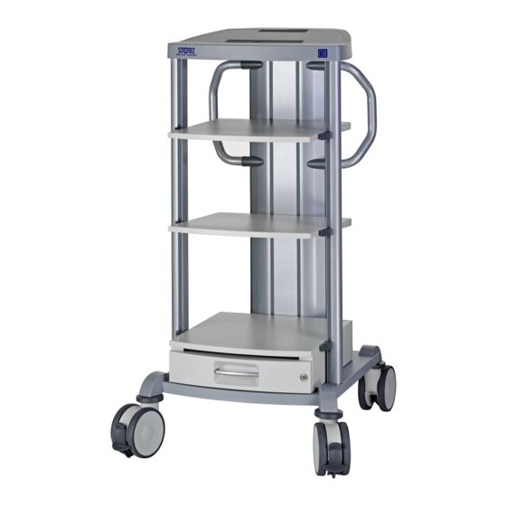
Product description 4 Product description 4.1 Description of operation 4.1.1 Equipment cart The central power supply to the equipment cart is supplied via the energy boom. In the energy boom with a power supply, the power lines of the electrical devices placed on the cart are connected to the isolation transformer and the potential equalization lines are connected to the potential equalization rail. - Page 12 Product description 4.2.1.1 Configuration examples Equipment cart, wide, high (UG220) Equipment cart, narrow, small (UG110) LC equipment cart (UG230) Equipment cart, narrow, high (UG120) Instructions for use • COR equipment cart series • KXH353_EN_V1.0_11-2020_IFU_CE-MDR...
-
Page 13: Boom Package
Product description 4.2.2 Boom package Energy boom Side boom, left Transport handles Side boom, right 4.2.3 Base module Base Locking brake Impact protection Double swivel castor 4.2.4 Cover The cover consists of the following components: – Frame with main power switch on right –... -
Page 14: Isolation Transformer
Product description 4.2.5 Isolation transformer Fuse holder for device fuses Potential equalization connector Connection for main power switch Power input connector Connection for earth leakage monitor Allen key IEC connector sockets Connection bridge 4.2.6 Earth leakage monitor Control and display element Test plug Evaluation element Connector for isolation transformer... -
Page 15: Holders For Monitors And Navigation Cameras
Product description 4.2.7 Holders for monitors and navigation cameras Monitor swivel arm (UG540) Fastening on the equipment cart Holding arm Swivel arm Holder 4.2.7.1 Holder models Monitor holding arm (UG520) Monitor holder (UG500) Monitor holding arm (UG510) Monitor holder adaptor (UG501) Monitor swivel arm, navigation camera (UG530) Instructions for use •... -
Page 16: Possible Combinations
Product description 4.3 Possible combinations The COR equipment cart can be combined with the following components, depending on the size and version. 4.3.1 Shelf 4.3.2 Drawer unit Drawer units come in two different sizes depending on the cart version. The number of drawers can be individually defined and depends on the boom length. -
Page 17: Holders For Endoscopes
Product description 4.3.4 Holders for endoscopes Flexible endoscopes (29005IFH) Double videoendoscope (13991DET) Videoendoscope (13991ET) 4.3.5 Equipment rails Equipment rail, short (UG607) Equipment rail, long (UG608) Instructions for use • COR equipment cart series • KXH353_EN_V1.0_11-2020_IFU_CE-MDR... -
Page 18: Holders For Special Applications
Product description 4.3.6 Holders for special applications Footswitch holder for one-pedal Multifunctional holder, long (UG623L) footswitch (29005EFH) Adaptor plates for CO bottle holder, Cable manager (UG619) twin (UG627) bottle holder (UG609) Tube clip (UG631) IV pole (UG616/UG625) Bracket (UG630) IV pole, height adjustable (UG617/ Footswitch holder for two-pedal UG626) footswitch (29005DFH) -
Page 19: Counterweights
COR service cover, narrow/wide (UG628/UG629) Camera holder (UG622) 4.3.7 Counterweights Counterweight plate (UG614) Additional weight (UG615) 4.4 Technical data 4.4.1 Equipment cart Designation UG110 UG120 UG210 UG220 UG230 Dimensions 660 x 1,265 660 x 1,474 840 x 1,265 840 x 1,265... -
Page 20: Boom Package
Product description 4.4.2 Boom package Designation UG040 UG041 UG050 UG051 UG055 UG052 Energy boom 580 x 992 x 130 mm 580 x 1,154 x 130 mm (W x H x D) Weight 23.5 kg 25.5 kg 22.5 kg Side boom 55 x 992 x 45 mm 55 x 1,154 x 45 mm (W x H x D) Power connec-... -
Page 21: Shelf
Product description 4.4.6 Shelf Designation UG603 UG604 Dimensions 450 x 25 x 510 mm 630 x 25 x 510 mm (W x H x D) Weight 4.5 kg 5 kg Max. load 60 kg 60 kg for shelf Equipment cart Narrow Wide 4.4.7 Holders for monitor and navigation camera Designation UG500 UG501... -
Page 22: Pull-Out Elements
Product description Designation UG617 UG618 UG619 UG622 Dimensions 1,200 – Ø 65 x 35 mm Ø 31.7 x 29 mm (W x H x D) 1,800 mm Weight 1.7 kg 0.15 kg 0.3 kg 0.03 kg Max. load 2 bottle hooks, 0.5 kg 5 kg each Application Infusion Videoendoscope Cable Camera plug... -
Page 23: Equipment Rails
Product description 4.4.11 Equipment rails Designation UG607 UG608 Dimensions 10 x 25 x 170 mm 10 x 25 x 300 mm (W x H x D) Weight 0.22 kg 0.32 kg Max. load 5 kg 5 kg 4.4.12 Counterweights Designation UG614 UG615 Dimensions 356 x 6 x 478 mm 290 x 6 x 478 mm (W x H x D) Weight... -
Page 24: Earth Leakage Monitor
Product description Designation UG300 UG310 Fuse type F20A-H ESKA 1038.631 (420020) T20A-H ESKA (option) 1038.331 (440020) F10A-H ESKA 1038.627 (420010) T10A-H ESKA (option) 1038.327 (440010) 10.3 x 38 mm 5 x 20 mm x (option) The fine-wire fuses must be labeled with UL/CSA approvals for the American market and with VDE/EN approvals for the European market. -
Page 25: Symbols Employed
Product description 4.5 Symbols employed 4.5.1 Symbols on the packaging Symbol Meaning Medical device Air pressure limit Humidity limit Keep dry Fragile, handle with care Manufacturer Date of manufacture Article no. Serial number Batch code Number of products in the product packaging In accordance with US federal law (21 CFR 801.109), this product may only be sold to or on prescription from a licensed physician. -
Page 26: Symbols On The Product
Product description Symbol Meaning Keep away from sunlight Do not use if package is damaged. Consult instructions for use 4.5.2 Symbols on the product Symbol Meaning Separate collection of electrical and electronic devices. Do not dispose of in household refuse. CE conformity mark With this mark, the manufacturer declares the compliance of the prod- ucts with the applicable regulation (EU) 2017/745. -
Page 27: System Description
Product description Storage/transport conditions (without electronic equipment) Temperature -20 °C ... +60 °C Relative humidity 5 – 95% Air pressure min. 700 – 1,060 hPa Operating conditions Temperature 0 °C ... +40 °C Relative humidity 30 – 75% Air pressure min. 700 – 1,060 hPa 4.7 System description This chapter describes the requirements for medical electrical systems according to IEC 60601-1: Medical electrical equipment, section 16. -
Page 28: Multiple Socket Outlets
4.7.6 Installation of the ME system The ME system must be set up and installed by qualified personnel who have been authorized by KARL STORZ. Persons who have been commissioned with assembly by the operator or the responsible organizations are solely responsible for their actions. -
Page 29: Maintenance
Product description 4.7.8 Maintenance Required maintenance work can be found in the instructions for use of the system components. When a video trolley is used, inspect the supply line for mechanical damage before each use of the system and arrange for a replacement to be carried out by a specialist if damage is detected. -
Page 30: Preparation
(Art. no. 96206915EN) and in the assembly video at http://www.karlstorz.com. A video on how to attach a monitor swivel arm to a COR equipment cart can also be found on the KARL STORZ website. KARL STORZ recommends that two persons assemble the cart. Please follow the assembly instructions and the assembly video. -
Page 31: Loading The Product
Preparation Securing options for bases Securing options for rail bases 5.4 Loading the product The center of gravity of the equipment cart changes as it is loaded. Load the shelves and drawers of the equipment cart from the bottom up. Load the monitor holding arms last. -
Page 32: Connecting The Product
Preparation Position the monitors in the direction of travel. Push in all pull-out elements (drawers, keyboard shelves and sliding tray holders). Lock all drawers. Release the locking brakes on the double swivel castors by pushing the brake lever upwards with your foot. Move the equipment cart by holding the handles or both side booms at the same time. -
Page 33: Connecting The Earth Leakage Monitor
Preparation Check that all supply lines and connecting cables are secure. Switch on the isolation transformer (ON = I) or plug in the power switch jumper plug (ST1). ð Voltage is present at the output. The devices can be switched on. 5.9 Connecting the earth leakage monitor Control and display element Power... - Page 34 Preparation Remove the test plug. ð The “Power on” LED lights up and signals the operational readiness of the earth leakage monitor. The system test has been performed successfully. ð The “Isolation” LED lights up. The system test has not been performed successfully. To continue testing the system, unplug one device after the other.
-
Page 35: Disassembly
Disassembly 6 Disassembly 6.1 Disconnecting the product from the power supply In the case of devices that store data, save the data. Switch off the power switches of the devices on the equipment cart. Switch off the central power switch of the equipment cart. Pull the plug of the power line out of the grounded socket. -
Page 36: Maintenance, Servicing, Repairs, And Disposal
Shut down the product. Have the deficiencies repaired by persons authorized by KARL STORZ. Regardless of the national accident prevention regulations and testing intervals for medical devices, for this device safety checks must be performed as repeat inspections according to IEC 62353 and recorded by a qualified electrician at least once a year. -
Page 37: Visual Inspection
Document the results of the safety test. 7.4 Repairing the product Repair work may only be performed by KARL STORZ or by a company authorized by KARL STORZ. The interventions described in this instruction manual are exempt from this rule. Please contact your local KARL STORZ subsidiary or authorized dealer (see the list of subsidiaries). - Page 38 Maintenance, servicing, repairs, and disposal Article Article number Monitor holder UG500 Monitor holding arm UG510 Monitor holding arm, long UG520 Swivel arm for navigation camera UG530 Monitor swivel arm UG540 IV pole UG616 IV pole, height adjustable UG617 Instructions for use • COR equipment cart series • KXH353_EN_V1.0_11-2020_IFU_CE-MDR...
-
Page 39: Accessories And Spare Parts
Accessories and spare parts 8 Accessories and spare parts 8.1 Accessories Article Order no. Power cord, length 100 cm UG700 Special power cord 15 A, length 100 cm UG700U Connecting cable, length 100 cm UG702 Power cord, US 15 A, length 500 cm UG709 Power cord, US 20 A, 500 cm UG710 Power cord, China, length 500 cm UG711... - Page 40 Accessories and spare parts Article Order no. COR, T-slot rubber profile for side boom ET21-1020 COR, cover for equipment rail ET21-1021 6-way terminal strip, long cable ET21-1022 6-way terminal strip, short cable ET21-1023 COR, assembly set ET21-1024 COR, screw set ET21-1025 COR, key for drawer ET21-1026...
- Page 41 Accessories and spare parts Article Order no. COR, accessories kit for UG500, UG510, ET71-SZ-B-001 UG520 COR, accessories kit for UG500, UG510, ET71-SZ-B-001 UG520 COR, accessories kit for navigation camera ET71-SZ-B-003 arm UG530 COR, cable conduit for UG500 ET71-SZ-B-004 COR, accessories kit for monitor holder ET71-SZ-B-005 UG501 Instructions for use •...
-
Page 42: Electromagnetic Compatibility
Electromagnetic compatibility 9 Electromagnetic compatibility 9.1 Table 1 – Compliance level for immunity tests Guidelines and manufacturer’s declaration – electromagnetic immunity The product is intended for use in the electromagnetic environment specified below. The user of the product should make sure that it is used in such an environment. Interference im- EN/IEC 60601 test Compliance level... - Page 43 Electromagnetic compatibility Interference im- EN/IEC 60601 test Compliance level Electromagnetic envi- munity tests level ronment – guidelines Magnetic field at 30 A/m at 50 Hz / 30 A/m at 50 Hz / If image distortion oc- the power fre- 60 Hz 60 Hz curs, it may be neces- quency (50/60 Hz) sary to install the prod- acc.
- Page 44 Electromagnetic compatibility Test fre- Frequency Radio service Modulation Immunity Compliance quency band test level level 1,970 LTE band 1, 3, 4, 25, UMTS 2,450 2,400 – 2,570 Bluetooth, Pulse modula- WLAN 802.11 tion b/g/n, 217 Hz RFID 2450, LTE band 7 5,240 5,100 –...
- Page 45 Electromagnetic compatibility Interference immunity EN/IEC 60601 test Compliance Electromagnetic envi- tests level level ronment – guidelines be less than the compli- ance level in each fre- quency range d = 1.2 √P 80 MHz to 800 MHz d = 2.3 √P 800 MHz to 2.5 GHz Interferences may occur in the vicinity of equipment marked with the following symbol:...
- Page 46 Electromagnetic compatibility 9.5 Table 5 – Recommended separation distances between portable and mobile HF communications devices and the product The device is intended for use in an electromagnetic environment in which HF disturbances are controlled. The customer or user of the device can help prevent electromagnetic interference by maintaining a minimum distance between portable and mobile HF communications equipment (transmitters) and the product as recommended below, according to the maximum output power of the communications device.
-
Page 47: Faults And Messages
Faults and messages 10 Faults and messages 10.1 Fault correction Fault Possible causes Actions The connected devices do Equipment cart not switched Switch on the central not work power switch on the equipment cart Device not switched on Switch on the power switch on the device Device power line not con- Check the device power... - Page 48 Faults and messages Fault Possible causes Actions Check the automatic cutout of the supply circuit Check the overcurrent safety switch in the output circuit of the isolation transformer Contact Service Earth leakage monitor does Equipment cart not switched Switch on the central not work power switch on the equipment cart...
-
Page 49: Subsidiaries
KARL STORZ Veterinary Endoscopy-America, Inc. Email: info-be@karlstorz.com 1 South Los Carneros Road, Goleta, CA 93117, USA KARL STORZ Endoscopie France S. A. S. Phone: +1 805 968-7776, Fax: +1 805 685-2588 12, rue Georges Guynemer, Quartier de l’Europe, 78280 Guyancourt, France Email: info@karlstorzvet.com... - Page 50 No. 8 Commonwealth Lane #03-02, Singapore 149555, Singapore Phone: +65 69229150, Fax: +65 69229155 KARL STORZ ENDOSKOPE – East Mediterranean and Gulf (Offshore) S.A.L. Email: infoasia@karlstorz.com Spark Tower 1st floor Charles Helou St., Horch Tabet – Sin El Fil, Beirut,...
- Page 51 Subsidiaries Instructions for use • COR equipment cart series • KXH353_EN_V1.0_11-2020_IFU_CE-MDR...
- Page 52 KARL STORZ SE & Co. KG Dr.-Karl-Storz-Straße 34 78532 Tuttlingen Postfach 230 78503 Tuttlingen Germany Phone: +49 7461 708-0 Fax: +49 7461 708-105 E-mail: info@karlstorz.com www.karlstorz.com...
Need help?
Do you have a question about the UG110 and is the answer not in the manual?
Questions and answers