
Subscribe to Our Youtube Channel
Related Manuals for joule ECOHEAT-160


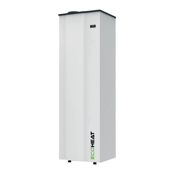
Summary of Contents for joule ECOHEAT-160
- Page 1 INSTALLATION AND USER MANUAL ECOHEAT - 160, 200 260l www.joule.ie | www.jouleuk.co.uk...
-
Page 2: Table Of Contents
INTRODUCTION GENERAL INDICATIONS TECHNICAL INFORMATION INSTALLATION STEPS PLACING ECOHEAT AIR CONNECTION HIDRAULIC CONNECTION ELECTRICAL CONNECTION COMISSIONING CONTROLLER WARRANTY CONDITIONS ECOHEAT INSTALLATION AND USER MANUAL... -
Page 3: Introduction
1. INTRODUCTION This product, has been manufactured according to the European Quality Standards, incorporates prime grade materials and its correct working has been tested before it leaves our facilities. Through this Installation and User Manual, you will be guide tow ards the correct and safe ty installation of the product. - Page 4 2.3. Package contents The ECOHEAT system comprises the following components: - ECOHEAT - Silent -Blocks - User Manual 2.4. Indications about transport and unpacking the unit The unit is supplied packed i nto a wooden pallet properly secured to prevent damage during transport.
-
Page 5: Technical Information
3. TECHNICAL INFORMATION 3.1. Operating Principle Compressor Evaporator: Extracts energy from the ambient Condenser: Transfers energy to the water Expanssion valve Figure 1: Operating principle 3.2. Dimension drawings It is possible to remove the side and front casing access easily to any part of the system. Figure 2: Exploded view ECOHEAT INSTALLATION AND USER MANUAL... - Page 6 Figure 3: D imension s, mm EH1 60 EH200 EH260 1297 1527 1945 13 23 Figure 4. Back connections Figur e 5. Front connections Power supply, 230 V/1PH/50 Hz Recirculation connection , ¾ ‘’ Condensate drain Electrical heater , 1500 W Hot water outlet, ¾...
- Page 7 3.3. Technical data M M o o d d e e l l E E H H 1 1 6 6 0 0 E E H H 2 2 0 0 0 0 E E H H 2 2 6 6 0 0 C C y y l l i i n n d d e e r r Capacity, L Maximum operating pressure, bar...
-
Page 8: Installation Steps
4. INSTALLATION STEPS Before starting the installation, check the availability of all the necessary components and tools: - Drill - Screwdriver - Hydraulic installation components - Electric installation components Once it has been checked that it is available all the necessary comp onents and tools, the installer should follow the next steps: 1. -
Page 9: Air Connection
6. AIR CONNECTION Ecoheat unit has two air connections located at the top cover of the system. There are different installations possibilities: Since the temperature of the exhaust air is lower t han the in take air flow, the user can recover this cold air to refresh a room. -
Page 10: Hidraulic Connection
7. HIDRAULIC CONNECTION The hydraulic connections are shown in the following scheme: The installer must i nstall the following components of the hydraulic circuit: - Cold water inlet (1) - Safety valve (7) - Ball valves (2) - Expansion vessel (8) - Pressure reducing valve (3) - Check valve (9) - Non- return valve (4) -
Page 11: Electrical Connection
8. ELECTRICAL CONNECTION The power supply of the system is 230 V/1/50 Hz. The power line must be protected by a circuit breaker of 2 poles / 16 A. The connection schem e is shown in the picture above. PV: Photovoltaic connection LPS: Low pressure switch HPS: High pressure switch NTC1 : Water temperatur e probe... -
Page 12: Comissioning Controller
9. COMISSIONING. CONTROLLER. 9.1. User interface description D E S C R I Symbol Meaning when it lights Compressor switched on Defrost active Fan switched on Alarm active Compressor working hours exceeded Unit in ºC Unit in ºF Electric heater switched on Stand by ECOHEAT INSTALLATION AND USER MANUAL... - Page 13 9.2. INSTALLATION - Switching on After full installation of the water heater (power and water pipes connected) and after the water heater tank is full of water, power can be turn ON. 1. A er filling the tank of water, connect the mains plug to the mains supply.
- Page 14 9.4. Unlocking the keypad When 30 have elapsed without the keys being pressed, the display will show the ‘’ LOC’’ label and the keypad will lock automatically Touch any key until the screen shows UnL , to unlock the keypad 9.5.
- Page 15 9.6. Changing operating mode To change the operating mode, touch the for 4 seconds. The screen will show blinking the selectable operating modes. Use the keys to select the operating mode. Touch to confirm or to cancel The screen will show again the water temperature ECOHEAT INSTALLATION AND USER MANUAL...
- Page 16 9.7. ECO Mode ECO mode: Maximum savings . The system h eats water only by heat pump technology. This is the f actory default mode. Setting the ECO temperature setpoint The water temperature set point in ECO mode can be changed with the SP1 parameter.
- Page 17 9.8. AUTO Mode It maintains a steady temperature by the heat pump and only use the electrical heater if the temperature falls drastically. Setting the AUTO temperature setpoint The water temperature set point in AUTO mode can be changed with the SP2 parameter.
- Page 18 9.9. OVERBOOST Mode Select this mode to achieve a fast heating by using simultaneously heat pump and electric heater. This mode Works as a rapid heating. Once the setpoint temperature is reached, the system returns to the initial mode. If Overboost mode is switched on when the system Works from ECO mode: The system heats the water up to SP1 , and then returns to ECO again...
- Page 19 Parameter SP3 allows to set the minimum temperature that Overboost can be actived. To change it value, follow the procedure: Touch and select with SP3. Touch to confirm The display will show the programmed temperature Touch to select the desired temperature Touch to confirm or cancel...
- Page 20 9.10. Photovoltaic input Working on this mode, the system automatically heats the water due to electric energy surplus or by Off Peak rate. The parameters of this mode can only be changed by the Installer’s Menu. Contact with the technician for more information The system can be combined with and Photovoltaic Inverter to take advantage of the surplus energy generated by the panels, by forcing the system working and storing this...
- Page 21 9.12. Antilegionella The anti-legionnella feature reduces the risk of development of bacteria in the tank. The system performs a thermal shock disinfection to avoid any risk co nditions that might cause the development of bacteria. The disinfection is made automatically once a month, reaching a temperature of 6 5 ºC.
-
Page 22: Warranty Conditions
10. WARRANTY CONDITIONS Component Warranty period Stainless steel 2205 tank 5 years Stainless steel 444 tank 3 years Electrical, electronic and mechanical removable components 2 years MANUFACTURER WARRANTY CONDITIONS The warranty exclusively covers productions faults of the product, excluding any liability for any material damage or injury that results directly or indirectly from the use of this product.
Need help?
Do you have a question about the ECOHEAT-160 and is the answer not in the manual?
Questions and answers