Table of Contents
Advertisement
Quick Links
Advertisement
Table of Contents

Subscribe to Our Youtube Channel
Related Manuals for Peak PCAN-RS-232


Summary of Contents for Peak PCAN-RS-232
- Page 1 PCAN-RS-232 User Manual User Manual 2.0.0 © 2022 PEAK-System Technik GmbH...
-
Page 2: Imprint
Duplication (copying, printing, or other forms) and the electronic distribution of this document is only allowed with explicit permission of PEAK-System Technik GmbH. PEAK-System Technik GmbH reserves the right to change technical data without prior announcement. The general business conditions and the regulations of the license agreement apply. -
Page 3: Table Of Contents
5.1 Uploading Firmware via CAN 5.2 Uploading Firmware via the Serial Connections 6 Technical Data Appendix A CE Certificate Appendix B Dimension Drawing Appendix C Port Assignment of the Microcontroller Appendix D Disposal Contents PCAN-RS-232 User Manual 2.0.0 © 2022 PEAK-System Technik GmbH... -
Page 4: Introduction
C and C++ and is then transferred to the module via CAN. Various programming examples facilitate the implementation of own solutions. On delivery, the PCAN-RS-232 is provided with a demo firmware that routes from CAN to RS-232 and vice versa. It allows to configure the data transfer as well as the hardware with serial control commands. -
Page 5: Properties At A Glance
Connection via a 10-pole terminal strip (Phoenix) Voltage supply from 8 to 30 V Extended operating temperature range from -40 to +85 °C (-40 to +185 °F) New firmware can be loaded via CAN interface 1 Introduction PCAN-RS-232 User Manual 2.0.0 © 2022 PEAK-System Technik GmbH... -
Page 6: Scope Of Supply
Power supply in the range of 8 to 30 V DC For uploading the firmware via CAN: CAN interface of the PCAN series for the computer (e.g. PCAN-USB) Operating system Windows 11 (x64), 10 (x86/x64) 1 Introduction PCAN-RS-232 User Manual 2.0.0 © 2022 PEAK-System Technik GmbH... -
Page 7: Connectors And Coding Solder Jumpers
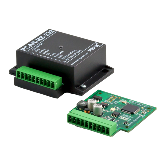
2 Connectors and Coding Solder Jumpers PCAN-RS-232 with 10 connector poles and one status LED The PCAN-RS-232 converter has a 10-pole screw terminal block for connecting the following components: Supply voltage RS-232 Digital input and digital output CAN bootloader activation... - Page 8 Furthermore the board has four coding solder jumpers in order to assign a fixed status to the corresponding input bits of the microcontroller. A concrete application is to identify a PCAN-RS-232 converter on the CAN bus for a firmware upload, especially if there are several converters connected and in operation.
-
Page 9: Screw Terminal Block
RS-232 interface RS-232 TxD For further connection details that are not needed for programming of the PCAN-RS-232 converter because of implementation in a library, see also Appendix C Port Assignment of the Microcontroller. 2 Connectors and Coding Solder Jumpers PCAN-RS-232 User Manual 2.0.0... -
Page 10: J5 Connector Panel: Jtag Ports
2.2 J5 Connector Panel: JTAG Ports The unpopulated connector panel J5 on the PCAN-RS-232 converter’s circuit board provides an access option to the JTAG ports of the LPC2194/01 microcontroller (μC) for hardware debugging. Gain access to the unpopulated J5 connector panel: Risk of short circuit! Soldering on the PCAN-RS-232 may only be performed by qualified electrical engineering personnel. - Page 11 Internal Wiring 1, 2 /Reset /Reset Pull-up 3.3 V P1.29 Pull-down (R30) P1.30 Pull-up P1.27 Pull-up P1.28 Pull-up RTCK P1.26 Pull-down (R31) TRST P1.31 Pull-up 2 Connectors and Coding Solder Jumpers PCAN-RS-232 User Manual 2.0.0 © 2022 PEAK-System Technik GmbH...
- Page 12 R30 for pin 5 TCK, R31 for pin 9 RTCK 6. Insert the circuit board and place the housing cover on top. 7. Screw the two screws back into their original positions. 2 Connectors and Coding Solder Jumpers PCAN-RS-232 User Manual 2.0.0 © 2022 PEAK-System Technik GmbH...
-
Page 13: Coding Solder Jumpers
(ID 0 - 3) are each assigned to one port of the microcontroller LPC2194/01 (μC). A bit is set (1) if the corresponding solder field is open. A concrete application is the identification of a PCAN-RS-232 on the CAN bus during a firmware upload, especially if several devices are connected and in operation. - Page 14 Activate coding solder bridges: Risk of short circuit! Soldering on the PCAN-RS-232 may only be performed by qualified electrical engineering personnel. Attention! Electrostatic discharge (ESD) can damage or destroy components on the card. Take precautions to avoid ESD. 1. Disconnect the PCAN-RS-232 from the power supply.
-
Page 15: Operation
The status indication of the LED depends on the used firmware. On delivery the PCAN-RS-232 is supplied with an example firmware that routes from CAN to RS-232 and vice versa. It allows to configure the data transfer as well as the hardware with serial control commands. -
Page 16: Creating Own Firmware
PEAK-System programmable hardware products. For each supported product, examples are included. On delivery the PCAN-RS-232 converter is supplied with the example firmware 6_CAN_TO_SER_BY_COMMAND that routes from CAN to RS-232 and vice versa. It allows to configure the data transfer as well as the hardware with serial control commands. - Page 17 Creating your own firmware: 1. Create a folder on your computer. We recommend using a local drive. 2. Unzip the development package PEAK-DevPack.zip completely into the folder. No installation is required. 3. Run the script SetPath_for_VSCode.vbs. This script will modify the example directories for the Visual Studio Code IDE.
-
Page 18: Library
8. Use the PEAK-Flash tool to upload your firmware to the PCAN-RS-232 via CAN. The tool is either started via the menu Terminal > Run Task > Flash Device or from the subdirectory of the development package. Chapter 5.1.3 Firmware Transfer describes the process. -
Page 19: Firmware Upload
CAN bus with 120 Ohm each. Operating system Windows 11 (x64), 10 (x86/x64) If you want to update several PCAN-RS-232 converters on the same CAN bus with new firmware, you must assign an ID to each converter. See section 2.3 Coding Solder Jumpers. - Page 20 Pay attention to the proper termination of the CAN cabling (2 x 120 Ohm). 4. Reconnect the power supply. Due to the High level at the Boot connection, the PCAN-RS-232 starts the CAN bootloader. This can be determined by orange quickly blinking of the status LED.
- Page 21 5.1.3 Firmware Transfer A new firmware version can be transferred to the PCAN-RS-232. The firmware is uploaded via a CAN bus using the Windows software PEAK-Flash. Transfer firmware with PEAK-Flash: The software PEAK-Flash is included in the development package, which can be downloaded via the following link: www.peak-system.com/quick/DLP-DevPack...
- Page 22 6. In the drop-down menu Bit rate, select the nominal bit rate 500 kbit/s. 7. Click on Detect. In the list, the PCAN-RS-232 appears together with the Module ID and Firmware version. If not, check whether a proper connection to the CAN bus with the appropriate nominal bit rate exists.
- Page 23 10. Select the corresponding file (*.bin). 11. Click Next. The Ready to Flash dialog appears. 12. Click Start to transfer the new firmware to the PCAN-RS-232. The Flashing dialog appears. 13. After the process is complete, click Next. 14. You can exit the program.
-
Page 24: Uploading Firmware Via The Serial Connections
CAN bootloader may be overwritten. Afterwards, a firmware upload via CAN is not possible anymore. Activate the microcontroller's bootloader: Risk of short circuit! Soldering on the PCAN-RS-232 may only be performed by qualified electrical engineering personnel. Attention! Electrostatic discharge (ESD) can damage or destroy components on the card. - Page 25 The LED remains off. 8. Insert the circuit board and place the housing cover on top. 9. Screw the two screws back into their original positions. 5 Firmware Upload PCAN-RS-232 User Manual 2.0.0 © 2022 PEAK-System Technik GmbH...
-
Page 26: Technical Data
Maximum voltage at load 60 V Maximum output current 0.7 A Power Supply Supply voltage (U 8 to 30 V DC Current consumption max. 70 mA at 12 V 6 Technical Data PCAN-RS-232 User Manual 2.0.0 © 2022 PEAK-System Technik GmbH... - Page 27 -40 to +85 °C (-40 to +185 °F) Temperature for storage -40 to +85 °C (-40 to +185 °F) and transport Relative humidity 15 to 90 %, not condensing Ingress protection IP20 (IEC 60529) 6 Technical Data PCAN-RS-232 User Manual 2.0.0 © 2022 PEAK-System Technik GmbH...
- Page 28 Conformity RoHS 2 EU Directive 2011/65/EU (RoHS 2) EU Directive 2015/863/EU DIN EN IEC 63000:2019-05; VDE 0042-12:2019-05 EU Directive 2014/30/EU DIN EN 61326-1:2013-07; VDE 0843-20-1:2013-07 6 Technical Data PCAN-RS-232 User Manual 2.0.0 © 2022 PEAK-System Technik GmbH...
-
Page 29: Appendix A Ce Certificate
Appendix A CE Certificate Appendix A CE Certificate PCAN-RS-232 User Manual 2.0.0 © 2022 PEAK-System Technik GmbH... -
Page 30: Appendix B Dimension Drawing
Appendix B Dimension Drawing Appendix B Dimension Drawing PCAN-RS-232 User Manual 2.0.0 © 2022 PEAK-System Technik GmbH... -
Page 31: Appendix C Port Assignment Of The Microcontroller
Appendix C Port Assignment of the Microcontroller The following table lists the used inputs and outputs (ports) of the LPC2194/01 microcontroller (μC) and their function in the PCAN-RS-232 converter. It is meant as supplemental information. The converter's functionality is implemented by the supplied library. - Page 32 (I). Before switching on the LED again, the respective port type must be set to output (O). Appendix C Port Assignment of the Microcontroller PCAN-RS-232 User Manual 2.0.0 © 2022 PEAK-System Technik GmbH...
- Page 33 JTAG Interface Debugging, J5:7 P1.28 JTAG Interface Debugging, J5:8 P1.29 JTAG Interface Debugging, J5:5 P1.30 JTAG Interface Debugging, J5:6 P1.31 JTAG Interface TRST Debugging, J5:10 Appendix C Port Assignment of the Microcontroller PCAN-RS-232 User Manual 2.0.0 © 2022 PEAK-System Technik GmbH...
-
Page 34: Appendix D Disposal
Appendix D Disposal The PCAN-RS-232 must not be disposed of in household waste. Dispose of the PCAN-RS-232 properly in accordance with local regulations. Appendix D Disposal PCAN-RS-232 User Manual 2.0.0 © 2022 PEAK-System Technik GmbH...
Need help?
Do you have a question about the PCAN-RS-232 and is the answer not in the manual?
Questions and answers