Makita KP312 Operating Manual
Hide thumbs
Also See for KP312:
- Instruction manual (57 pages) ,
- Parts breakdown (3 pages) ,
- Brochure (1 page)
Table of Contents
Advertisement
Quick Links
T
ECHNICAL INFORMATION
Models No.
Description
C
ONCEPTION AND MAIN APPLICATIONS
These new Power Planers have been developed as sister tools
to the existing Makita models KP301 or KP311, excelling
predecessors both in power and convenience.
Model KPS312S features soft start circuit
and overload protector.
<Note>
Supply of Model KP312 is restricted to low voltage
(110V - 120V) area.
S
pecification
Voltage (V)
120
Voltage (V)
230
220
Model No.
No load speed (min
Planer Blade (mm [in])
Soft Start
Overload Protector
Protection from Electric Shock
Cord Length : m ( ft )
Net Weight :Kg (lbs )
Planing width : mm [in]
0 - 150 [0 - 5-7/8]
150 - 240 [5-7/8 - 9-1/2]
240 - 312 [9-1/2 - 12-9/32]
S
tandard equipment
For Model KP312
* Socket wrench 9 ................ 1 pc.
* Triangular rule .................... 1 pc.
< Note > The standard equipment for the tool shown may differ from country to country.
O
ptional accessories
* Nozzle set
* Joint assembly
* Planer blade 312mm
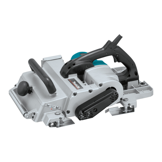
KP312, KP312S
Planers 312mm (12-9/32")
Current (A)
Cycle (Hz)
50 / 60
15
Current (A)
Cycle (Hz)
50 / 60
10
50 / 60
11
= rpm)
-1
W
KP312
Continuous Rating (W)
Input
1,700
KP312S
Continuous Rating (W)
Input
2,200
2,200
KP312
12,000
312 [12-1/4]
No
No
Double Insulation
10 [32.8]
18 [39.7]
Capacity
Planing depth : mm [in]
3.5 [1/8]
2.0 [1/16]
1.5 [1/16]
For Model KP312S
* Hex wrench ........................ 1 pc.
* Nozzle assembly ............... 1 pc.
* Triangular rule .................... 1 pc.
* Joint 70 .............................. 1 pc.
L
Dimensions : mm ( " )
551 (21-3/4)
Length ( L )
Width ( W )
425 (16-3/4)
Height ( H )
219 (8-5/8)
Max. Output(W)
Output
690
2,450
Max. Output(W)
Output
820
3,000
3,850
1,040
KP312S
Yes
Yes
PRODUCT
P 1 / 8
H
Advertisement
Table of Contents

Related Manuals for Makita KP312


Summary of Contents for Makita KP312
- Page 1 Model KPS312S features soft start circuit and overload protector. <Note> Supply of Model KP312 is restricted to low voltage (110V - 120V) area. Dimensions : mm ( " ) 551 (21-3/4) Length ( L )
- Page 2 P 2 / 8 epair < 1 > Lubrication Apply MAKITA grease N. No.1 to the following portions marked with black triangle to protect parts and product from unusual abrasion. (67) Armature (68) (69) (46) Spindle complete (74) (86) hex socket head bolt M10x40 Item No.
- Page 3 P 3 / 8 epair < 3 > Removing V- Pulleys (1) Attach the following bit to the impact driver. D=5mm 110mm 1R230 Multi-purpose M6 for hex socket head bolt M6x12 * Socket bit 17 for hex nut M10x17. 13mm And remove hex nut M10x17 and hex socket head bolt M6x12 with the impact driver.
- Page 4 P 4 / 8 epair (2) Mount poly V-belt. See Fig. 5. (3) Fasten hex socket head bolt M6x12 and hex nut M10-17 firmly until both V-pulleys turn as illustrated in Fig. 6. Wrench 17 Turn the wrench anti-clockwise for fastening. Poly V-belt Hex wrench Turn the hex wrench clockwise...
- Page 5 P 5 / 8 epair (2) Mount the armature to motor bracket. When mounting armature to motor bracket, align the coupling's spline with the spline of spindle, by slowly turning V-pulley 9-23L. Coupling Motor bracket Slowly turn V-pulley 9-23L to align the spline of spindle with the couplings spline.
- Page 6 P 6 / 8 epair < 8 > Replacement of the electrical parts in handle ( 1 ) Remove the following screws. ( 2 ) Removed handle R. The electrical parts can be replaced. 1. Pan head screw M5x28 : 4 pcs. See Fig.13.
- Page 7 P 7 / 8 ircuit diagram Color index of lead wires Black KP312 White Black or brown without soft start feature Orange and over current relay White or blue iring diagram KP312 without soft start feature and over current relay...
- Page 8 P 8 / 8 ircuit diagram Color index of lead wires Black KP312S White Black or brown with soft start feature Orange and over current relay White or blue Over current relay Soft start Noise circuit suppressor Connect noise suppressor as per the circuit diagram, iring diagram if any.
Need help?
Do you have a question about the KP312 and is the answer not in the manual?
Questions and answers