
Related Manuals for QEED QC-POWER-T-TA


Summary of Contents for QEED QC-POWER-T-TA
- Page 1 ANALIZZATORE DI RETE TRIFASE QC-POWER-T-TA Manuale d’Uso User Manual THREE-PHASE NETWORK ANALYSER...
- Page 3 Caratteristiche tecniche pag. Descrizione pag. Dimensioni pag. Installazione pag. Impostazione parametri di programmazione pag. Visualizzazione grandezze pag. 10 Comunicazione seriale pag. 13 Messaggi di errore pag. 18 Norme armonizzate di riferimento pag. 19 - 1 - Manuale d’Uso QC-POWER-T-TA...
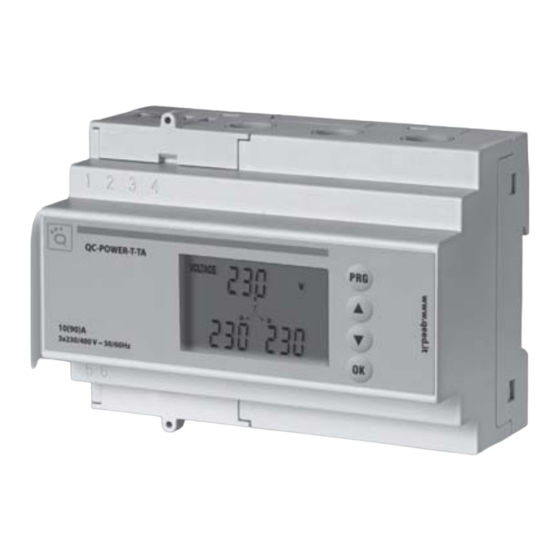
- Page 4 ANALIZZATORE DI RETE TRIFASE Leggere attentamente tutte le istruzioni L’analizzatore di rete QC-POWER-T-TA è un multimetro digitale per sistemi trifase ad inserzione diretta fino a 90A per misure di vero valore efficace (TRMS). L’uscita seriale RS-485 permette di visualizzare ed archiviare i dati su PC.
- Page 5 − Fattore di potenza (cos ) di fase e di sistema − Frequenza − inserzione 3 fili con Neutro − = 90 A − − − 25 mm − − − RISOLUZIONE E PRECISIONE − − − - 3 - Manuale d’Uso QC-POWER-T-TA...
- Page 6 − − − − − − − − − =90A) − − =90A) − − − − − - 4 - Manuale d’Uso QC-POWER-T-TA...
- Page 7 DESCRIZIONE VISTA FRONTALE MORSETTI E TASTI non equilibrati) Tasto di conferma e di visualizzazione grandezze di sistema Tasto pagina precedente Tasto pagina successiva Tasto di Programmazione - 5 - Manuale d’Uso QC-POWER-T-TA...
- Page 8 DIMENSIONI (mm) VISTA FRONTALE VISTA LATERALE 125.7 INSTALLAZIONE SCHEMA DI COLLEGAMENTO I max 90A Nota: Il collegamento del conduttore di Neutro può essere omesso SOLO per sistemi trifasi equilibrati e simmetrici - 6 - Manuale d’Uso QC-POWER-T-TA...
- Page 9 − impostazione retroilluminazione − azzeramento energia attiva e reattiva totali − configurazione uscita seriale RS-485 Si esce dalla programmazione quando si è confermata l’ultima pagina oppure se non 1) DATA E VERSIONE SOFTWARE INTERNO - 7 - Manuale d’Uso QC-POWER-T-TA...
- Page 10 2) GESTIONE RETROILLUMINAZIONE successiva (Azzeramento contatore Energia Attiva) 3) AZZERAMENTO CONTATORE ENERGIA ATTIVA successiva (Azzeramento contatore Energia Reattiva) 4) AZZERAMENTO CONTATORE ENERGIA REATTIVA - 8 - Manuale d’Uso QC-POWER-T-TA...
- Page 11 5) RS-485 INDIRIZZO per impostare il valore 6) RS-485 VELOCITA’ DI COMUNICAZIONE 7) RS-485 BIT DI PARITÀ - 9 - Manuale d’Uso QC-POWER-T-TA...
- Page 12 All’accensione dello strumento viene visualizzata la pagina principale che visualizza si visualizzano successivamente tutte le principale. Premendo il tasto si visualizza la pagina precedente. singola fase (attiva o reattiva). pagina principale tensioni di fase tensione di sistema tensioni concatenate - 10 - Manuale d’Uso QC-POWER-T-TA...
- Page 13 (*) fattore di potenza di sistema (*) A seconda della natura del carico, la lettera “c” indica fattore di potenza capacitivo, mentre la lettera “L” indica uno sfasamento induttivo - 11 - Manuale d’Uso QC-POWER-T-TA...
- Page 14 - 12 - Manuale d’Uso QC-POWER-T-TA...
- Page 15 START ADDRESS FUNCTION DATA CRC CHECK T1-T2-T3-T4 8 BITS 8 BITS # X 8 BITS 16 BITS T1-T2-T3-T4 PROCEDURA DI CALCOLO DELL’ERROR CHECK - 13 - Manuale d’Uso QC-POWER-T-TA...
- Page 16 = Potenza attiva di sistema = Potenza reattiva di sistema = Potenza apparente di sistema PF = Fattore di potenza di sistema = Energia attiva totale = Energia reattiva totale = frequenza (fase1) 0009 (0009-1) =0008 - 14 - Manuale d’Uso QC-POWER-T-TA...
- Page 17 ° 30027 30061 ° 30029 30063 [kW/10] 30031 30065 [kvar/10] 30033 Tutte le misure contenute nei registri di input (ad eccezione dei contatori di energia) Segno Esponente Mantissa 1 Bit 8 Bit 23 Bit - 15 - Manuale d’Uso QC-POWER-T-TA...
- Page 18 1 = 1 azzera il solo contatore di energia attiva bit 2 = 1 azzera il solo contatore di energia reattiva ERRORI DI COMUNICAZIONE RILEVABILI messaggio sia indirizzato correttamente) - 16 - Manuale d’Uso QC-POWER-T-TA...
- Page 19 Max =3ms (a 4800bps) Max =1.5ms (a 9600bps) Tempo di risposta dell Min = 25ms Typ = 30ms Max =100ms Tempo min tra due messaggi di richiesta del master Min = 100ms Typ > 1s - 17 - Manuale d’Uso QC-POWER-T-TA...
- Page 20 (fase 2) ERRORE DI SOVRATENSIONE O SOVRACORRENTE Si verifica quando il valore efficace TRMS di una o più fasi di ingresso supera la tensione trattini “--- - 18 - Manuale d’Uso QC-POWER-T-TA...
- Page 21 Lo strumento riprende la visualizzazione del dato in maniera corretta quando la ERRORE DI CONFIGURAZIONE Errore di configurazione NORME DI RIFERIMENTO 2006/95/CE 2004/108/CE (EMC) Sicurezza Compatibilità Elettromagnetica Prescrizioni Metrologiche - 19 - Manuale d’Uso QC-POWER-T-TA...
-
Page 23: Table Of Contents
23 Description page 25 Dimensions page 26 Installation page 26 Selecting programming parameters page 27 Reading of quantities page 30 Serial communication page 33 Error messages page 38 Reference standards page 39 - 21 - User Manual - QC-POWER-T-TA... -
Page 24: Safety Instructions
7) Do not power or connect the device if any part of it is damaged. NOTE: Network analyzer QC-POWER-T-TA is aimed for use in places with over- voltage category III and pollution degree, 2 as per EN 61010-1... -
Page 25: Technical Specifications
TECHNICAL SPECIFICATIONS − − − − − − − 3-wire connection with neutral − = 90 A − − − ; maximum diameter of − − − RESOLUTION AND ACCURACY − − − - 23 - User Manual - QC-POWER-T-TA... - Page 26 − − − − − − − − − =90A) − − =90A) − − − − − - 24 - User Manual - QC-POWER-T-TA...
-
Page 27: Description
DESCRIPTION FRONT VIEW TERMINALS AND KEYS - 25 - User Manual - QC-POWER-T-TA... -
Page 28: Dimensions
DIMENSIONS (mm) FRONT VIEW SIDE VIEW 125.7 INSTALLATION WIRING DIAGRAM I max 90A NOTE: Connection of the neutral conductor may ONLY be omitted for balanced symmetrical three-phase systems - 26 - User Manual - QC-POWER-T-TA... -
Page 29: Selecting Programming Parameters
− viewing built-in software version and date − configuring serial output RS-485 or . As soon as the last page is confirmed the programming mode is exited; this also occurs 1) DATE AND VERSION OF BUILT-IN SOFTWARE - 27 - User Manual - QC-POWER-T-TA... - Page 30 2) BACKLIGHTING CONTROL 3) ZEROING THE ACTIVE-ENERGY METER 4) ZEROING THE REACTIVE-ENERGY METER address) - 28 - User Manual - QC-POWER-T-TA...
- Page 31 5) RS-485 ADDRESS to select the value communication speed) 6) RS-485 COMMUNICATION SPEED to select the desired speed 7) RS-485 PARITY BIT - 29 - User Manual - QC-POWER-T-TA...
-
Page 32: Reading Of Quantities
READING OF QUANTITIES to view the previous page. Main page Phase voltage System voltage Voltage between lines (chain) - 30 - User Manual - QC-POWER-T-TA... - Page 33 System apparent power Phase reactive power System reactive power Phase power factor (*) System power factor (*) Depending on load type, “c” stands for capacitive power factor, whereas “L” stands for inductive phase shift - 31 - User Manual - QC-POWER-T-TA...
- Page 34 Total active energy Phase active energy Total reactive energy Phase reactive energy Frequency - 32 - User Manual - QC-POWER-T-TA...
-
Page 35: Serial Communication
FUNCTION DATA CRC CHECK T1-T2-T3-T4 8 BITS 8 BITS #X 8 BITS 16 BITS T1-T2-T3-T4 ERROR CHECK CALCULATION PROCEDURE CRC in the message. The receiver device recalculates the CRC during the reception of - 33 - User Manual - QC-POWER-T-TA... - Page 36 Function for the reading of the registers in which the measurements are memorised. The instrument allows to obtain the value of all available measurements (33) with a single request. subtracting one from the register number. 0009 (0009-1) =0008 - 34 - User Manual - QC-POWER-T-TA...
- Page 37 30021 30055 30023 30057 ° 30025 30059 ° 30027 30061 ° 30029 30063 [kW/10] 30031 30065 [kvar/10] 30033 Sign Exponent Mantissa 1 Bit 8 Bit 23 Bit (e 127) * (1+ m)* 2 - 35 - User Manual - QC-POWER-T-TA...
- Page 38 Quantity of coils Hi (n.u.) Force Data Hi 1/2/4 Force Data Lo (n.u.) CRC1 CRC2 COMMUNICATION ERRORS DETECTED SERIAL COMMUNICATION TIMES The communication protocol has no restrictions with regard to the response time of a master. - 36 - User Manual - QC-POWER-T-TA...
- Page 39 Max =3ms (a 4800bps) Max =1.5ms (a 9600bps) lave response time Min = 25ms Typ = 30ms Max =100ms Minimum time between two request messages from Min = 100ms the Master Typ > 1s - 37 - User Manual - QC-POWER-T-TA...
-
Page 40: Error Messages
ERROR MESSAGES MISCONNECTION into the current-measuring through holes OVER-VOLTAGE OR OVER-CURRENT ERROR - 38 - User Manual - QC-POWER-T-TA... -
Page 41: Reference Standards
CONFIGURATION ERROR disappears. Configuration error REFERENCE STANDARDS 2006/95/EC 2004/108/EC (EMC) Safety Electromagnetic compatibility Metering requirements - 39 - User Manual - QC-POWER-T-TA... - Page 44 QUALITY ELECTRONIC DESIGN 32013 Longarone (BL), Italy Z.I. Villanova, 20 Ph. +39 0437 761021 Fax +39 0437 760024 www.qeed.it - info@qeed.it...
Need help?
Do you have a question about the QC-POWER-T-TA and is the answer not in the manual?
Questions and answers