
Related Manuals for QEED QC-POWER-T-485


Summary of Contents for QEED QC-POWER-T-485
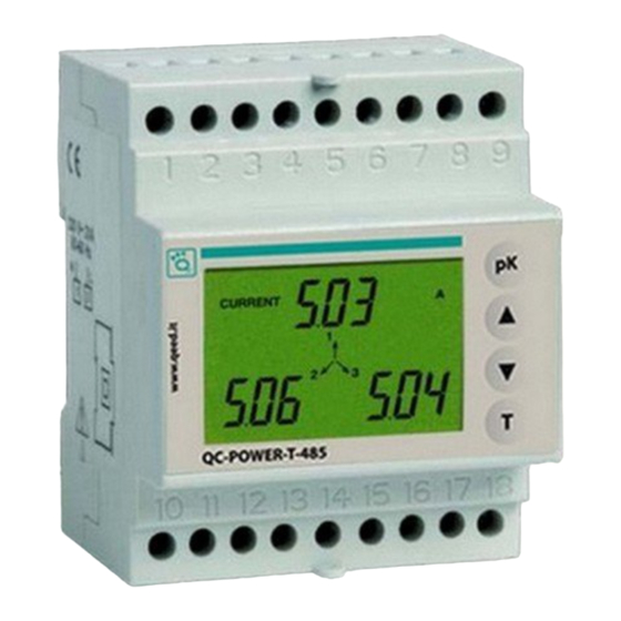
- Page 1 Analizzatore di Rete trifase QC-POWER-T-485 Manuale d’Uso Network Analyser User Manual...
-
Page 3: Table Of Contents
Impostazioni parametri Pagina Visualizzazione pagine di misura Pagina Metodo di misura / calcolo Pagina 13 Comunicazione seriale Pagina 14 Norme di riferimento Pagina 19 Dimensioni e schemi di collegamento Pagina 20 - 1 - Manuale d’Uso - Analizzatore di Rete QC-POWER-T-485... -
Page 4: Avvertenze Di Sicurezza
Deve essere presente un dispositivo di protezione delle sovracorrenti. CARATTERISTICHE TECNICHE Alimentazione: 230 VAC (-15%/+10%) - 2 - Manuale d’Uso - Analizzatore di Rete QC-POWER-T-485... -
Page 5: Descrizione Strumento
Campi numerici per la visualizzazione dei valori delle grandezze misurate Tipo di misurazione in corso TASTI Visualizzazione delle grandezze di sistema Visualizzazione del valore di picco delle grandezze e selezione dei parametri in fase di programmazione - 3 - Manuale d’Uso - Analizzatore di Rete QC-POWER-T-485... -
Page 6: Impostazioni Parametri
Nota: per i primari del TV e del TA è impostabile qualsiasi valore tra 0001 e 9999. Se si imposta il valore 0000 lo strumento forza il valore a 0001. - 4 - Manuale d’Uso - Analizzatore di Rete QC-POWER-T-485... - Page 7 Impostazione velocità porta seriale: premere il tasto “pK” per selezionare una tra (1200, 2400, 4800 o 9600 Baud) tasto “T” Impostazione bit di parità: premere il tasto “pK” tra le opzioni “NONE” “ODD” o “EVEN” tasto “T” - 5 - Manuale d’Uso - Analizzatore di Rete QC-POWER-T-485...
- Page 8 “pK” per selezionare una tra le opzioni “NO” (retroilluminazione “YES” (attivata) o “TIME” un tasto) “T” Alla pressione del tasto “T” Nota: se durante la fase di programmazione viene a mancare la tensione di momento dello spegnimento. Manuale d’Uso - Analizzatore di Rete QC-POWER-T-485...
-
Page 9: Visualizzazione Pagine Di Misura
“T” si visualizza la pagina della tensione di sistema 2a) Pagine valori di picco delle tensioni di fase VOLTAGE VOLTAGE VOLTAGE “pK” si visualizzano nell’ordine: “V” che lampeggia - 7 - Manuale d’Uso - Analizzatore di Rete QC-POWER-T-485... - Page 10 4) Pagina correnti di fase CURRENT CURRENT correnti di fase “T” si visualizza la corrente di sistema 4a) Pagine valori di picco delle correnti di fase CURRENT CURRENT CURRENT - 8 - Manuale d’Uso - Analizzatore di Rete QC-POWER-T-485...
- Page 11 6) Pagina potenze apparenti di fase POWER POWER APPARENT APPARENT potenze apparenti di fase “T” si visualizza la potenza apparente di sistema 7) Pagina potenze reattive di fase POWER POWER REACTIVE REACTIVE - 9 - Manuale d’Uso - Analizzatore di Rete QC-POWER-T-485...
- Page 12 “T” si visualizza il fattore di potenza di sistema 9) Pagina sfasamenti tensioni-correnti gli sfasamenti tensione-corrente in gradi sessagesimali (la lettera “C” “L” uno sfasamento - 10 - Manuale d’Uso - Analizzatore di Rete QC-POWER-T-485...
- Page 13 ENERGY energia reattiva totale “T” si visualizzano le energie reattive parziali delle singole fasi (tali energie vengono azzerate ogni volta che viene incrementata l’energia reattiva totale) 12) Pagina frequenza FREQUENCY - 11 - Manuale d’Uso - Analizzatore di Rete QC-POWER-T-485...
- Page 14 “up” ( ) o “down” ( ) per selezionare il valore desiderato della cifra lampeggiante “pK” “T” lampeggiano l’ora e la data nelle pagine dei valori di picco. - 12 - Manuale d’Uso - Analizzatore di Rete QC-POWER-T-485...
-
Page 15: Metodo Di Misura /Calcolo
Potenza apparente di sistema Fattore di potenza di sistema PF = Energia attiva totale E = E 1 +E 2 +E 3 Energia reattiva totale Er = Er 1 +Er 2 +Er 3 - 13 - Manuale d’Uso - Analizzatore di Rete QC-POWER-T-485... -
Page 16: Comunicazione Seriale
START ADDRESS FUNCTION DATA CRC CHECK T1-T2-T3-T4 8 BITS 8 BITS ?X 8 BITS 16 BITS T1-T2-T3-T4 Procedura di calcolo dell’error check - 14 - Manuale d’Uso - Analizzatore di Rete QC-POWER-T-485... - Page 17 Elenco holding register (in formato esadecimale): 40001 KTA (primario trasformatore amperometrico) 40002 KTV (primario trasformatore voltmetrico) Read input register (04): consente di ottenere con una singola interrogazione un numero di registri superiore a - 15 - Manuale d’Uso - Analizzatore di Rete QC-POWER-T-485...
- Page 18 30039 [VA] 30007 [VA] 30041 [VA] 30009 [var] 30043 [VA] 30011 30045 [var] 30013 30047 [var] 30015 30049 [var] 30017 30051 30019 30053 30021 30055 30023 30057 30025 30059 30027 30029 30031 30033 Manuale d’Uso - Analizzatore di Rete QC-POWER-T-485...
- Page 19 Tutte le misure contenute nei registri di input (ad eccezione dei tempi e dei contatori Esponente Mantissa Il valore è codificato come: (e 127) * (1+ m)* 2 Force multiple coil (15) Elenco coil (e relativi indirizzi): - 17 - Manuale d’Uso - Analizzatore di Rete QC-POWER-T-485...
- Page 20 Il protocollo di comunicazione non prevede alcun vincolo riguardo il tempo di risposta da Prossimo messaggio di richiesta Master Messaggio di risposta Slave sono vincolate da determinati valori massimi il tempo necessario al Master (PC) per - 18 - Manuale d’Uso - Analizzatore di Rete QC-POWER-T-485...
-
Page 21: Norme Di Riferimento
Tempo di risposta dell slave Tempo min tra due messaggi di richiesta del master NORME DI RIFERIMENTO 2006/95/CE 2004/108/CE (EMC) è dichiarata con riferimento alle seguenti norme armonizzate: Sicurezza Compatibilità Elettromagnetica Prescrizioni Metrologiche - 19 - Manuale d’Uso - Analizzatore di Rete QC-POWER-T-485... -
Page 22: Dimensioni E Schemi Di Collegamento
DIMENSIONI GMk Wh VOLTAGE Hz VARh CURRENT FREQUENCY POWER APPARENT REACTIVE ENERGY 10 11 12 13 14 15 16 17 18 - 20 - Manuale d’Uso - Analizzatore di Rete QC-POWER-T-485... - Page 23 SCHEMI DI COLLEGAMENTO QC-POWER-T-485 RS-485 Monofase QC-POWER-T-485 RS-485 Trifase QC-POWER-T-485 RS-485 Trifase+N - 21 - Manuale d’Uso - Analizzatore di Rete QC-POWER-T-485...
- Page 25 Index Instrument description Page Measurement / calculation methods Page Reference standards Page Dimensions and connection diagrams Page - 23 -...
- Page 26 SAFETY WARNINGS During the installation and operation of the instrument, proceed in accordance with the instructions below: 1) The instrument should be installed by competent personnel 2) Follow the installation diagrams carefully 3) When connecting the instrument, always use TA x/5 A 4) The appliance should be installed in a panel from which no access can be gained to the terminals after installation 5) The terminals of the voltage and current circuits may be connected with a...
- Page 27 INSTRUMENT DESCRIPTION Display and messages GMk Wh VOLTAGE Hz VARh CURRENT FREQUENCY POWER APPARENT REACTIVE ENERGY GMk Wh VOLTAGE Hz VARh CURRENT FREQUENCY POWER APPARENT REACTIVE ENERGY Measurement unit KEYS - 25 -...
- Page 28 PARAMETER SETTING “up” ( ) and “down” ( ) “up” ( ) and “down” ( ) TV setting VOLTAGE VOLTAGE “up” ( ) or “down” ( ) “pK” “T” TA setting CURRENT CURRENT Note: for the TV and TA primaries, any value from 0001 to 9999 can be set. If the value 0000 is set, the instrument will force this to 0001.
- Page 29 Serial port configuration Setting the serial port address: the same as the TV setting procedure Setting the serial port speed: press “pK” (1200, 2400, 4800 o 9600 Baud) “T” Setting the parity bit: press “pK” to select one of the options “NONE” “ODD” or “EVEN”...
- Page 30 Zeroing the active energy meter ACTIVE ACTIVE ENERGY ENERGY “pK” to select the option “YES” or “NO” “T” Zeroing the reactive energy meter REACTIVE REACTIVE ENERGY ENERGY Rear lighting handling “pK” to select from the options “NO” “YES” (on) or “TIME” “T”...
- Page 31 DISPLAYING THE MEASUREMENT PAGE When “up” ( ) When “up” ( ) If V is >999 or I K or M 1) Main page The system voltage, current and active power 2) Phase voltage page VOLTAGE VOLTAGE phase voltages “T” system voltage 2a) Peak phase voltage value page VOLTAGE...
- Page 32 “pK” and “T” at the same time “up” ( ) 3) Concatenating voltage page VOLTAGE concatenating voltages 4) Phase current page CURRENT CURRENT phase currents “T” system current 4a) Peak phase current value page CURRENT CURRENT CURRENT - 30 -...
- Page 33 5) Active phase power page POWER POWER ACTIVE ACTIVE active phase powers “T” active system power 5a) Peak active power value pages POWER POWER POWER ACTIVE ACTIVE ACTIVE 6) Apparent phase power page POWER POWER APPARENT APPARENT apparent phase powers “T”...
- Page 34 reactive phase powers “T” reactive system power 7a) Reactive power peak value pages POWER POWER POWER REACTIVE REACTIVE REACTIVE 8) Phase power factor page phase power factors “T” system power factor 9) Voltage-current phase shift page voltage-current phase shifts “C” “L”...
- Page 35 10) Total active energy page k Wh ACTIVE ACTIVE ENERGY ENERGY total active energy “T” partial active energy of the single phases (these 11) Total reactive energy page VARh VARh REACTIVE REACTIVE ENERGY ENERGY total reactive energy “T” partial reactive energy readings for the single 12) Frequency page FREQUENCY - 33 -...
- Page 36 13) Time and date page “pK” “up” ( ) 13a) Setting the time and date “T” “up” ( ) or “down” ( ) “pK” “T” - 34 -...
- Page 37 MEASUREMENT / CALCULATION METHOD V 1 + V 2 + V 3 System voltage I 1 + I 2 + I 3 System current Active system power P = P 1 +P 2 +P 3 Reactive system power Q = Q 1 +Q 2 +Q 3 (addition) Apparent system power System power factor...
- Page 38 SERIAL COMMUNICATION Characteristics of the Modbus protocol Message structure receiver has to recognise the incomplete message condition and assume that the START ADDRESS FUNCTION DATA CRC CHECK T1-T2-T3-T4 8 BITS 8 BITS #X 8 BITS 16 BITS T1-T2-T3-T4 Error check calculation procedure Funzioni Modbus implementate Read holding register (03)
- Page 39 0004 40005 calendar: minutes – seconds Read input register (04): - 37 -...
- Page 40 0009 Address Dimension Unit Address Dimension Unit 30001 30035 30003 30037 30005 30039 [VA] 30007 [VA] 30041 [VA] 30009 [var] 30043 [VA] 30011 30045 [var] 30013 30047 [var] 30015 30049 [var] 30017 30051 30019 30053 30021 30055 30023 30057 30025 30059 30027 30029...
- Page 41 Address Dimension Unit Address Dimension Unit 30091 30093 30071 30095 30073 [var] 30097 30075 30099 30078 30101 30081 30103 30084 30105 [var] 30087 30107 [var] 30089 30109 [var] Mantissa The value is encoded as: (e 127) * (1+ m)* 2 Force multiple coil - 39 -...
- Page 42 Preset multiple register Communication errors detected 01 – illegal function 02 – illegal data address 03 – illegal data value Serial communication times Request message Next request message Master Response message Slave - 40 -...
- Page 43 Time Description lave response time the Master REFERENCE STANDARDS 2006/95/EC 2004/108/EC (EMC) Safety Electromagnetic compatibility Metering requirements - 41 -...
- Page 44 DIMENSIONS GMk Wh VOLTAGE Hz VARh CURRENT FREQUENCY POWER APPARENT REACTIVE ENERGY 10 11 12 13 14 15 16 17 18 - 42 -...
- Page 45 CONNECTION DIAGRAMS QC-POWER-T-485 RS-485 Single phase QC-POWER-T-485 RS-485 Three phase QC-POWER-T-485 RS-485 Three phase+N - 43 -...
- Page 48 QUALITY ELECTRONIC DESIGN 32013 Longarone (BL), Italy Z.I. Villanova, 20 Ph. +39 0437 761021 Fax +39 0437 760024 www.qeed.it - info@qeed.it...
Need help?
Do you have a question about the QC-POWER-T-485 and is the answer not in the manual?
Questions and answers