Advertisement
Quick Links
Operation manual
E461501
Rev 01
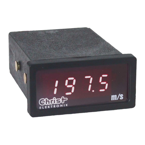
Operation manual CAM 100
Digital panel meter for Voltage / Current DC
About this manual:
Read this manual carefully for safety instructions and operating guidance before installation!
Christ-Elektronik GmbH • Alpenstrasse 34 • D-87700 Memmingen
Tel. +49 (0) 83 31/83 71 - 0 • Fax +49 (0) 83 31/83 71 - 99
Advertisement

Related Manuals for Christ Elektronik CAM 100


Summary of Contents for Christ Elektronik CAM 100
- Page 1 Operation manual E461501 Rev 01 Operation manual CAM 100 Digital panel meter for Voltage / Current DC About this manual: Read this manual carefully for safety instructions and operating guidance before installation! Christ-Elektronik GmbH • Alpenstrasse 34 • D-87700 Memmingen...
- Page 2 2.1 Starting Standard input & display ranges at the CAM 100 can be selected through solder pads as shown in table 1. With the resistor Rs any display range can be realised for voltage and current measurements. Also the decimal point is selected through a sol- der pad.
- Page 3 2.3 Rear view and solder pads Picture 2: Solder Pads Picture 1: Connecting diagram Zero Gain Potentio- Potentio- 1 2 3 4 5 6 meter „V“ meter “NP! 8 7 6 5 4 3 2 1 Solder Pads V / mA 5 / 12 / 24 V Solder Side Voltage / Current...
- Page 4 3 Technical data Display Display 7 – Segment display, 8 mm LED red ± 1999 digits Display range Decimal point via jumper Measurement range Display „1“ at overrange or sensor break Display „-1“ at underrange Measurement functions Measurement range attitude via solder bridge Meas.
Need help?
Do you have a question about the CAM 100 and is the answer not in the manual?
Questions and answers